12. Molding and casting
Group assignment for this week:
- Review the safety data sheets for each of your molding and casting materials
- Make and compare test casts with each of them
The documentation of group assignment can be found on our group work page.
During the group work it was great to see the whole process and the differences between the various casting options, as I have never done this kind of molding and casting before! A few different casting options also gave more insight into the possibilities of this technique for making different types of molds. Especially the silicone mold making caught my interest this time.
Individual assignment for this week:
- Design a mold around the stock and tooling that you'll be using, mill it (rough cut + three-axis finish cut), and use it to cast parts
Mold design
As a molding idea, I wanted to make something out of silicone. For the final product, I was thinking something from candles to soap to chocolate, but while talking to my mom about these, I got the idea for a bird DIY winter food. So the idea would be to melt for example coconut oil and/or some fat and mix in various seeds and harden them in a mold. These self-made bird foods could then be hung on home trees.
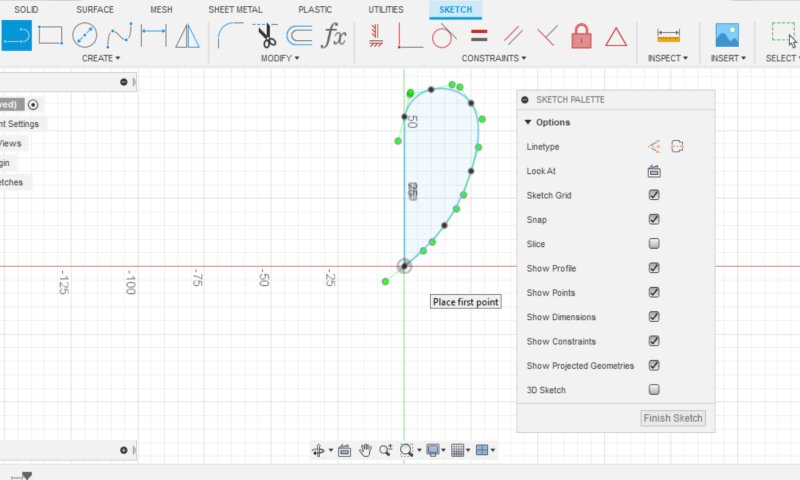
I was thinking about the shape of the mold, and as I was going to use only the recommended 3.175 mm milling bit, I guess the shape of the small mold couldn't be too detailed. I was thinking something like a pine cone, but I figured I couldn't really get it to look like anything if I didn't also shape the surface and that wasn't really possible in this time frame and with my 3D modelling skills at the moment. I was almost doing a typical heart and sketched the heart halves (in the pictures below), until I decided late that night to start sketching out some kind of pine cone anyway.
|
|
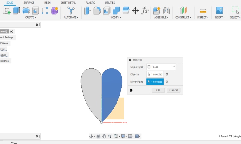
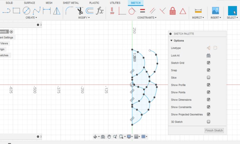
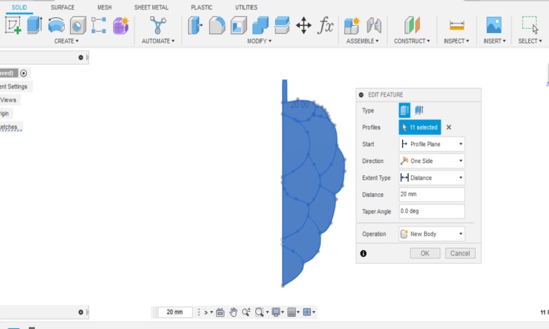
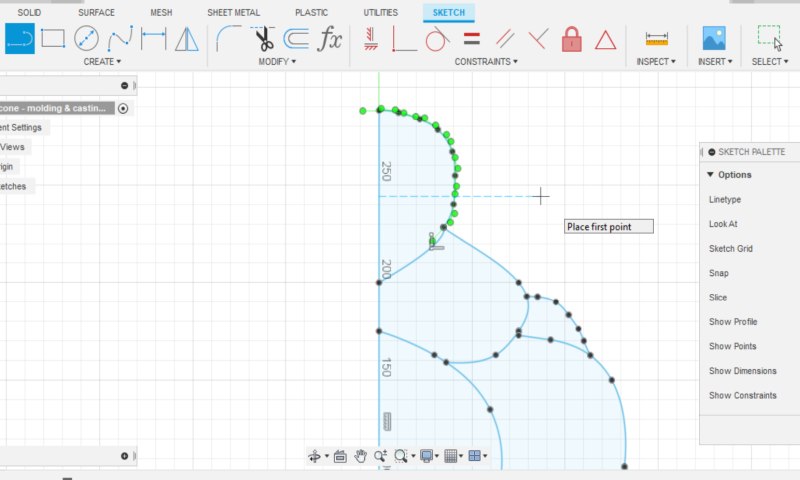
I sketched the pine cone using the Fit Point Spline tool. Picture below left. I made one half, extruded it and mirrored it to a whole using the y-axis. Picture below right. When I extruded the sketch, I realized that this would lose the details of my sketch. However, it was easier for me to create the shape of the pine cone using the individual circular shapes. I didn't have the energy at this point to start figuring out or thinking about how else to build the pine cone, so I went with this idea. Because I guess sketching wasn't the most important part of this process, but getting to learn how to make molding and casting.
|
|
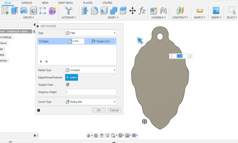
When I was modelling I noticed that some small changes had to be made. I made a hole at the top of the pine cone to make it easy to thread the finished product through the hole. To make the hole, I had to make the top end wider and rounder. Picture below left.
The assignment was that the milling should be done in three-axis finish cut, so I started rounding the edges of the pine cone with Fillet tool. At first this didn't work because the shape of the pine cone prevented rounding the edges. I then decided to use Fillet tool to round the pine cone shapes by 4 mm. Picture below right. Now, I was able to get a maximum fillet of 1.6 mm on the edges. I went with that. The final result can be seen in the pictures below.
|
|
I wanted to make a mold with several pine cones, but not really small pine cones, so I spent some time sizing the mold. I had about a 9 cm wide area in a piece of wax and probably over twenty centimetres in height, but it would have taken time to mill a large mold of that size. I decided to make the size of the mold about 9 x 13 cm.
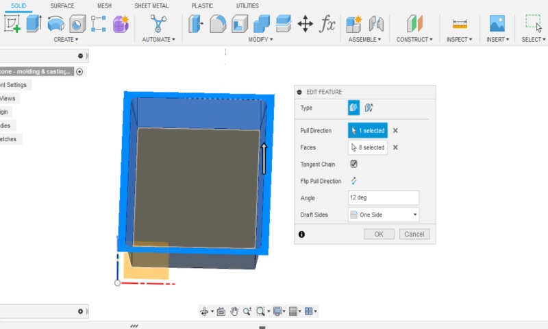
So I drew a rectangle and extruded it to the thickness of the wax piece. I made a shell, the walls I set at 5 mm thick. Then I used Fillet tool to make roundings in the inside corners, because it's not possible to mill rectangular inner shapes. I also used Draft tool to make 12 degrees angle on the inside walls to make the milling work. Picture below left.
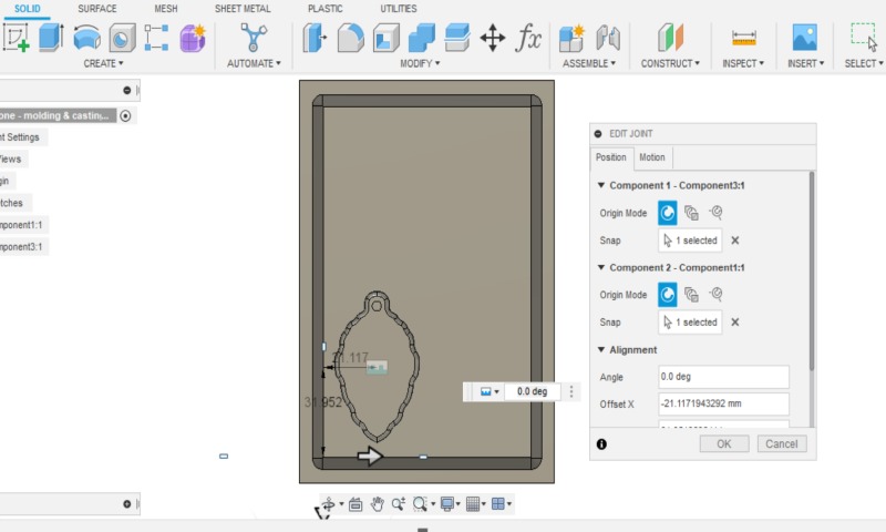
Now I had the parts for the mold, so I joined them together using Joint tool. Picture below right.
|
|
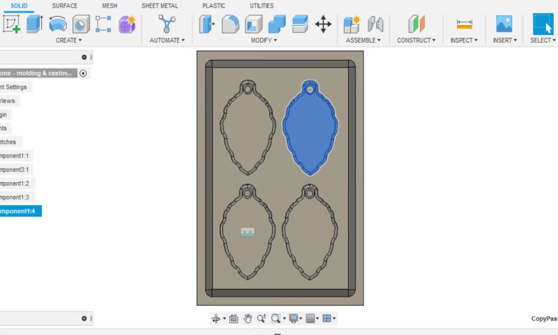
Next, I copied the pine cones one by one and moved them to the right places inside the rectangle using Move tool. Picture below left.
Finally, I used the Section Analysis tool and checked that there was enough space on each side for the milling bit. Picture below right.
|
|
Toolpaths for milling
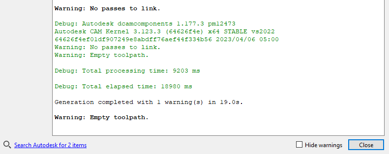
With the help of an instructor, I started to make toolpaths of the design. I did them on the Fusion Manufacture workspace. I crated New Setup, checking if the X, Y and Z axes are in the right directions, if not, change them from Orientation -> Select X and Y-axes. First I did the rough cut toolpaths with the 3D Pocket option and it went well. Then I continued with the finish cut by trying the 3D Parallel option and it didn't work properly, instead I got the warnings shown in the picture below.
For a while the instructor tried and tested alternative ways to solve the problem, but no solution was found at this point to remove the warnings.
The instructor advised me to choose 3D Adaptive Clearing as a "foolproof" option, which would make one-time milling comparable to finish cut. I managed to make the toolpaths with this option and the milling time showed about 2h.
I used the following settings:
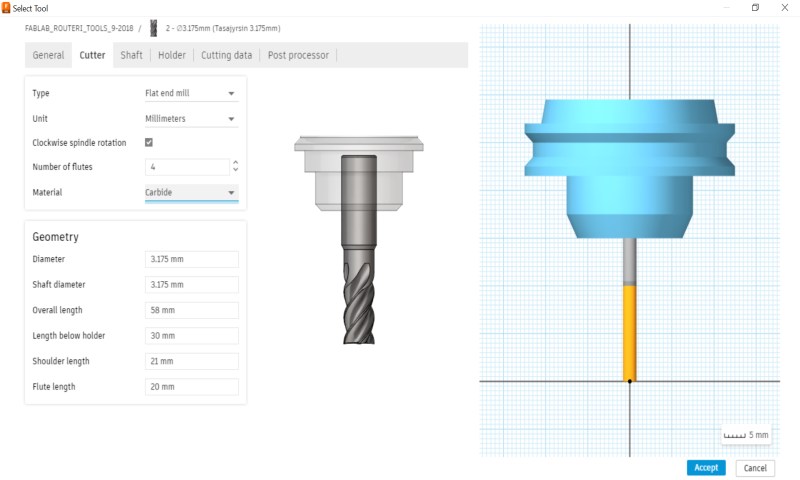
In Tool tab, I had to make a new tool in the tool selection. When I pressed select tool, a new window opened, I navigated to the FABLAB_ROUTERI... library I had downloaded earlier in week 7. There I made a duplicate of the 3 mm flat mill (by right-clicking on the tool) and started editing its settings (by right-clicking on the tool).
When I edited the tool, in General Tab, I named the Tool as "Tasajyrsin 3.175mm" (Flat mill 3.175mm) under Description. By the way, I am using the longer milling bit of this size.
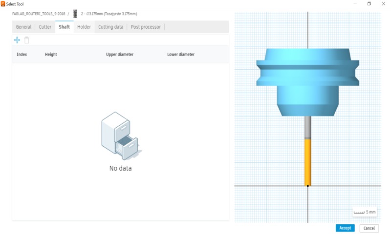
In the Cutter tab, I set the values, which are shown in the picture below left. In the Shaft tab, nothing needed to be changed or added. Picture below right.
|
|
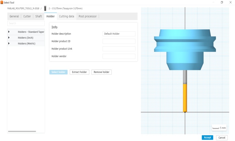
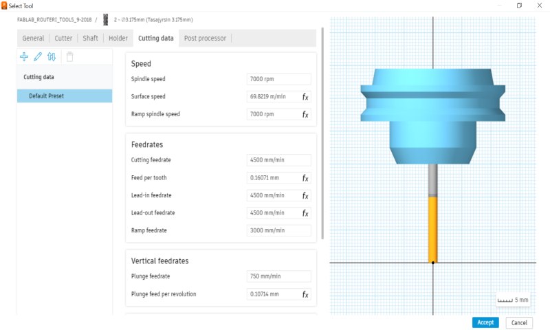
In the Holder tab, nothing needed to be changed or added. Picture below left. In the Cutting data tab I set the values, which are shown in the picture below right. And in Post processor tab, nothing needed to be changed or added. Now a new tool is ready and can be selected for use.
|
|
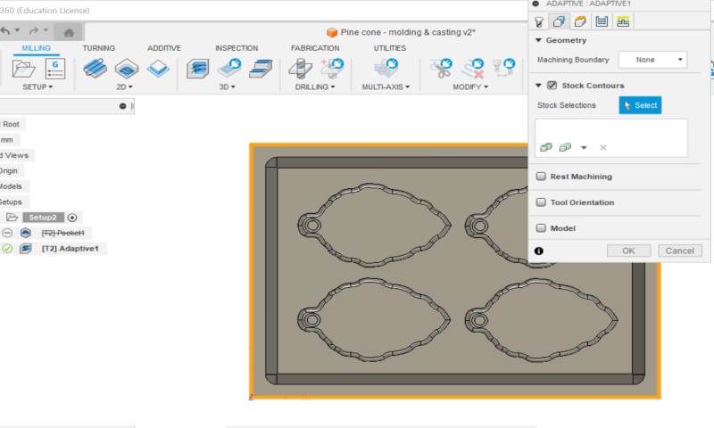
In Geometry tab, I deactivated "Rest Machining" option. Picture below left.
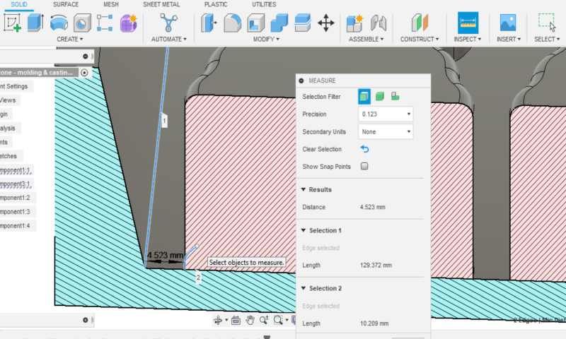
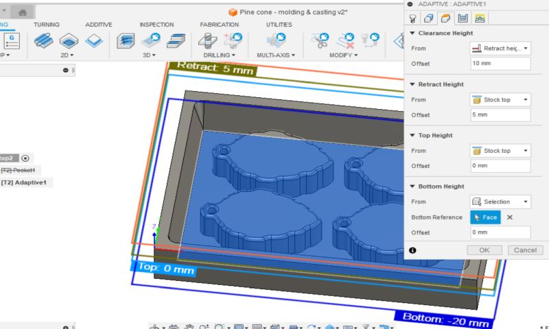
In Heights tab, I selected from Bottom Height drop-down menu option "Selection" and set the Bottom Height to the inner bottom of the mold. I checked the dimensions on the design. Picture below right.
|
|
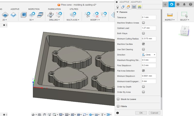
In Passes tab, I changed the Maximum Roughing Stepdown to 0.5 mm and Fine Stepdown to 0.2 mm. I deactivated "Stock to Leave" option. Picture below left.
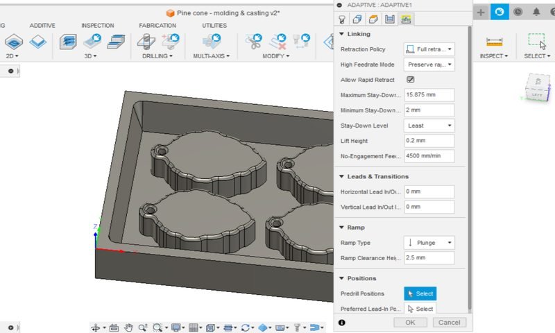
In Linking tab, I zeroed the Horizontal and Vertical Lean In/Out Radius values and changed the Ramp Type to Plunge. Picture below right.
|
|
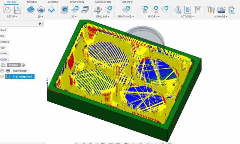
When I pressed OK, it took a moment for the Fusion to work through the settings and then showed the mess built up inside the mold as shown in the picture below.
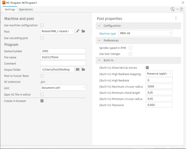
The final step was the Post Process. I applied Roland RML from Fusion 360 Library to the Post section and named the file. Picture below. Now the toolpaths were ready, I took the file to my memory stick and it was time to move on to the milling machine.
Milling
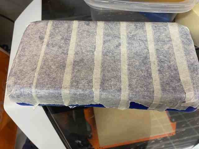
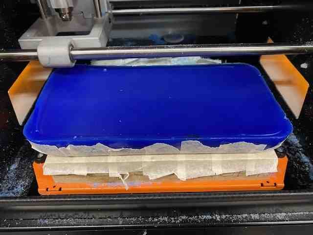
For milling I used Roland SMR-20 milling machine at Fab Lab Oulu. I taped the bottom of the wax piece and checked the milling machine's sacrificial board taping. Picture below left. I used hot glue to attach the wax piece to the sacrificial board. The hot glue must be applied quickly so that the glue does not have time to cool and harden before the piece is pressed onto the board. Picture below right.
|
|
Next, I attached the milling bit and set the origin points. Then I just opened the file and started the milling. These steps are the same as when we used Roland in week 8. Instructions on our group work page.
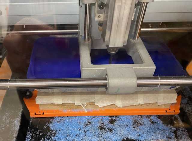
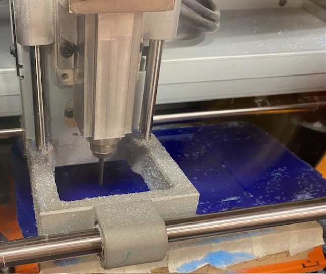
I watched curiously as the machine started to mill and soon realized that I had set the Z origin point way too high. The edges of the wax piece were much higher than the centre, so the bit was milling air and it looked like it would be milling air for at least the next, if not the next two layers. Picture below left.
I decided to stop the milling and set the Z origin point again in the middle of the wax piece. The wax is so soft that the bit can easily mill through the thicker mass in the beginning. And now it started to happen, a light wax shavings started to appear. Picture below right.
|
|
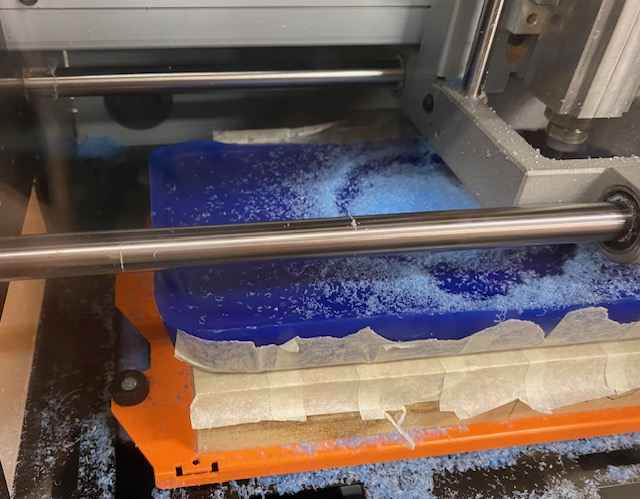
About an hour later, at the expected halfway point in the milling process, I cleaned the shavings off so they wouldn't get stuck in the milling process. I looked at the milled area and was surprised that only a few millimetres had been milled, even though we were already halfway through, but I thought maybe the milling would somehow speed up... Picture below left.
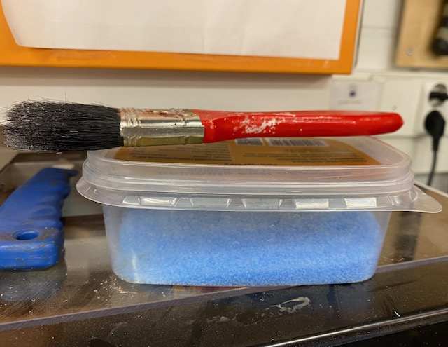
I cleaned up the shavings in a box using a paintbrush. Picture below right. The shavings will be re-melted into wax pieces, so they shouldn't be vacuumed or put in the trash.
|
|
Two hours went by and the milling had not stopped. Three hours after the milling started, we started the global lecture, so I thought, maybe the milling will stop soon, during the break I can see the result, at the latest after the lecture I can see the result. But no. The milling hadn't stopped. Well, actually, at the end of the lecture the milling had stopped, but in a strange way, the milling bit was in the middle of the milling area.
The computer had gone into automatic shutdown and that's why the milling had stopped. To my surprise, when I turned the computer back on to see what had happened, the milling machine immediately started milling again. Immediately, after I had just turned on the computer, I had not even had time to see the desktop or start the milling from the VPanel program. Quite surprising, and also terrifying, if something happened to the machine when it automatically turned on!
When I took a closer look at the restarted milling, I found that it had started again from scratch. How funny. I decided to stop the milling and figure out the next day how to continue with the job.
The next day I cleaned most of the shavings out of the mold to see what the current milling result was. I measured the depth of the mold and it was still a couple of millimeters under, so it would probably have taken another 1-2h of milling. Yikes. I thought it was going to be another long while if I somehow tried to get to the right milling point and continue milling to the end. So I decided to remove the mold. I discussed this with the instructor, and we came to the conclusion that maybe in the Fusion the simulation hadn't been able to account for all the shifts and speed variations, and that's why the milling took so much longer than the estimated time.
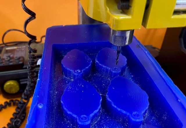
There were still some slight height differences at the bottom of the mold, but fortunately, thanks to the choice of 3D Adaptive Clearing, the milling was still smooth, so the milling was pretty successful anyway. The only thing that needed extra work was that the pine cones were missing holes, so I made them with a small pillar drill. Picture below left. When using a pillar drill, it would be advisable if not required to always have something other than a hand to hold the piece to be drilled, but in this case, as wax is a soft material to drill, and the piece didn't fit in the drill clamp, I held the piece with my hand. The bit drilled easily into the material, so the piece didn't move at all in the hand grip. I drilled holes of a little over 2 mm in diameter instead of the planned 3.6 mm, as 3.6 mm seemed too wide and I was afraid that the edges of the hole would be too thin. Finished mold in the picture below right.
|
|
Silicone mold
Then to make a silicone mold. I first measured the mixture that would go into the mold with water. It was around half a cup and I wondered if the mixture would come out when using the vacuum chamber. Well, I decided to try with a cup and that amount anyway. I dried the wax mold with compressed air.
I used Smooth-Sil 936 for this casting, because I had heard good things about it from my fellow students and the product was new and runny, so it would be easy to work with and pour into the mold. And actually, now that I'm writing this documentation and reading more about that product, I found out that it's not in the "suitable for food related applications" family, so I'm not making anything to eat for anybody in this mold, oops. Although, anyways, the food things made with these molds are not really recommended to be eaten, because the machines used to make the mold are also used for other jobs and thus the environment is not food safe.
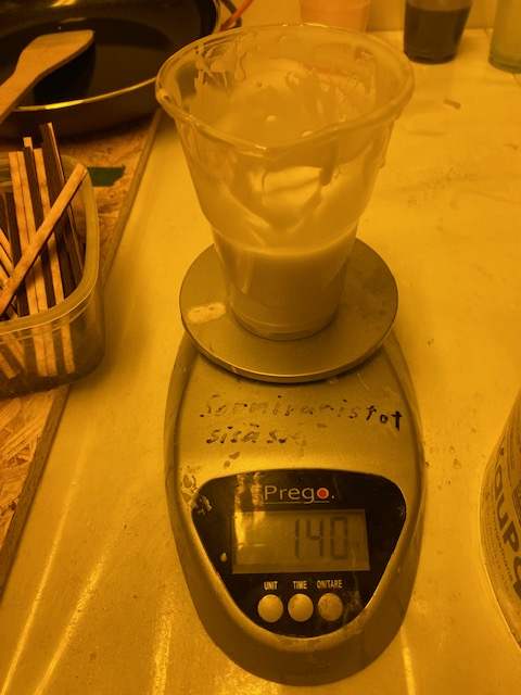
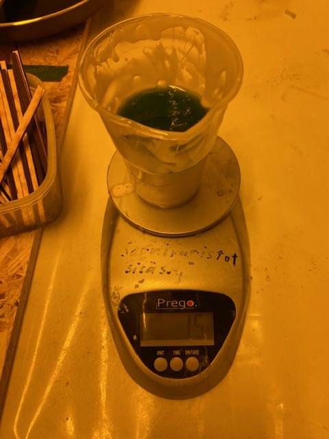
Well back to the Smooth-Sil 936 mixture. I equipped myself with protective clothing, checked the ventilation and started mixing the ingredients, the mixing ratio was 100A:10B. At first I mixed the ingredients in their bottles with a clean stick. Then I put ingredient A in a cup, half a cup took about 140 g. Picture below left. I managed to drop 15 g of ingredient B into the cup. Picture below right. Then started to stir the mixture gently around the edges.
|
|
Fortunately, the pot life of this product was 60 min, so there was no rush. When I thought the ingredients were well mixed, I put the cup in the vacuum chamber. I don't have any more pictures of these steps because I was doing this alone, so I couldn't easily stop to take pictures anymore. But you can find pictures of the mixing, vacuum chamber process and pouring on our group work page. In the vacuum chamber the mixture was about to bubble over, but I stopped the vacuum and let it settle, then turned it back on. Now it didn't bubble as much anymore. After the vacuum chamber, I started pouring the mixture into the mold gently.
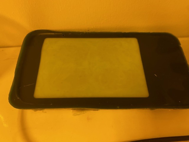
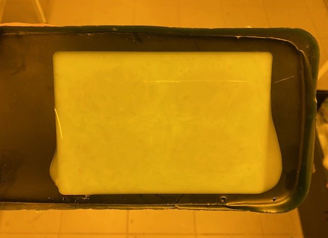
The mixture was just enough, although it was nearly down to the last drop. I left it to dry for 24 hours, which was the cure time for this product. Picture below left.
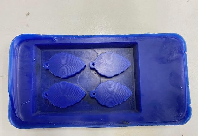
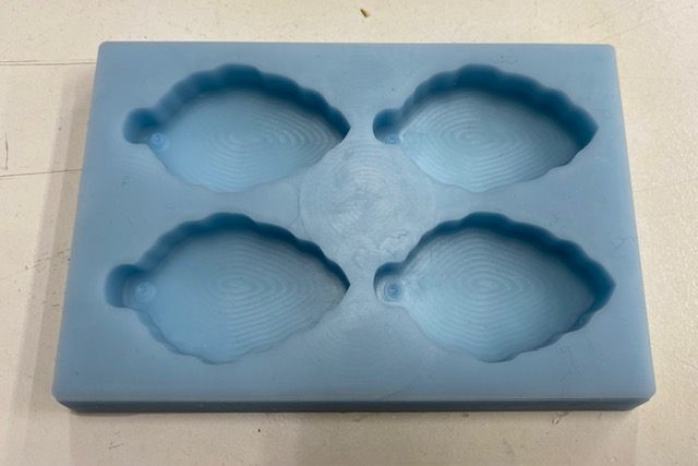
The next day, I was excited to pick up the silicone mold. It looked good at first sight and came off the wax mold easily. Picture below right.
|
|
On closer look, I noticed that the silicone mixture had not gone into the 2 mm wide holes, although I would have thought it would. Perhaps the holes were too narrow. When I looked at for example Marta Cortés Orduña's documentation, the 3-4 mm holes had worked, but she had also had problems with pouring and had used a stick to help. Perhaps I should also have taken the holes more into account when pouring the mixture.
But the lack of pins doesn't matter so much in the end, I can drill a hole in the finished product if I want to. Smooth-Sil 936 was easy to use and the end result has no bubbles and the mold feels nice and flexible.
Casting
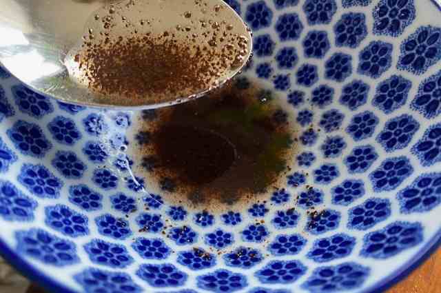
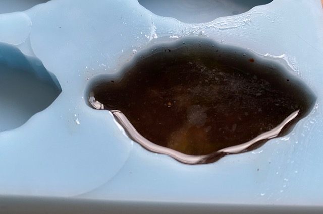
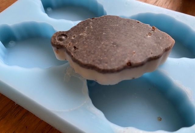
Now that I found out that my mold is not suitable for food related applications, I could then make little soap bars or coconut oil coffee scrubs or bath bombs with summer herbs or something like that. This time I did a casting experiment with coconut oil and coffee grounds, because they were easily available at home. I melted some coconut oil in the microwave oven, mixed in some coffee grounds and poured the mixture into the mold. Pictures below. I only made one piece, as I don't need more at the moment. I put the mold in the fridge to help the mixture harden faster.
|
|
After about half an hour I checked how the mixture looked like and dared to take the piece out of the mold. Of course the coffee grounds had settled to the bottom, but it doesn't matter, it's still usable and looks surprisingly nice like this. I'm happy with the mold despite its minor imperfections!
Download Pine Cone mold STEP file (I chose the STEP file because the F3D file would have been so big.)