Final project
Im green with envy, wishing for an abundance of greenery!
What if ?
What if there was a food pod ?
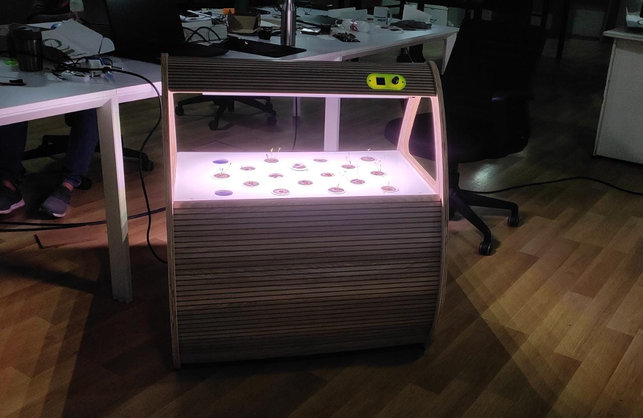
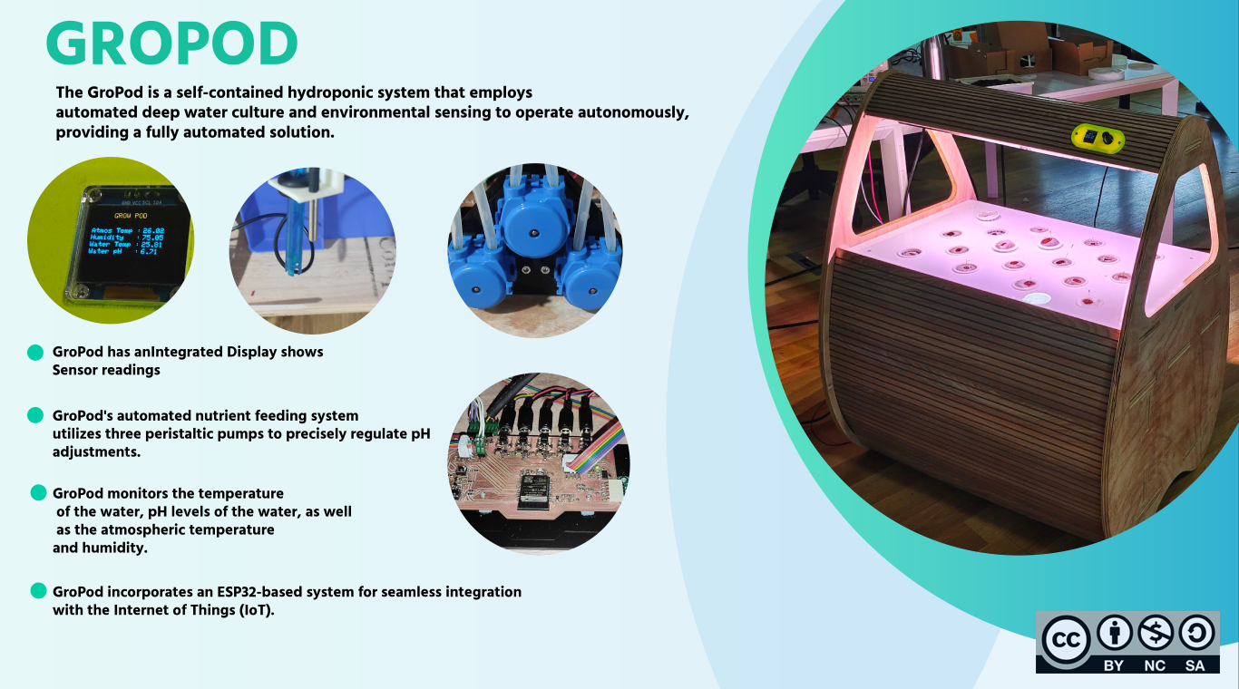
Imagine a system meticulously crafted for cultivating edible plants using a preferred method. This system is not only portable, but it also boasts a visually captivating design and complete automation.
Experience the unparalleled convenience, efficiency, and versatility of growing fresh food in any environment, be it indoors or outdoors.
Through its automated functionality, this food pod simplifies the growing process, making it accessible to even those with limited gardening expertise or time availability.
With features like automated nutrient delivery, precise lighting controls, and climate regulation, it guarantees optimal conditions for robust plant growth.
Ideation and Concept Development .
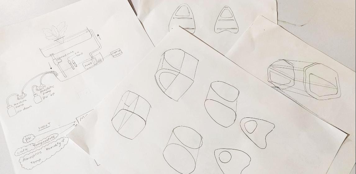
Brain storming and exploring different concepts to a structural design
I had coined how I want my hydroponic pod to function on week 1
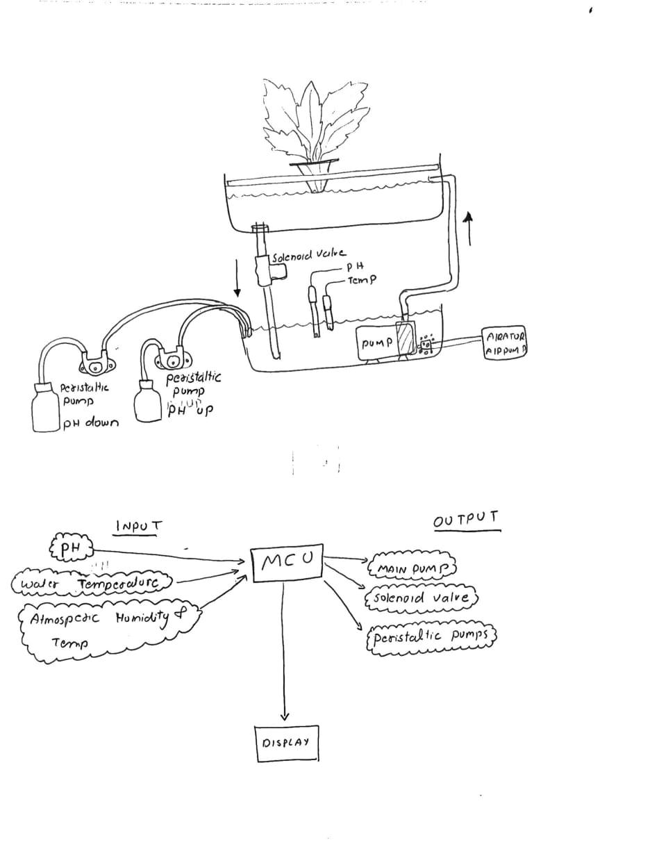
How it functions , I was thinking about incorporating deep water culture in to my hydroponic pod . as stated on week 1 hydroponic system in which plant roots are suspended in a nutrient-rich water solution. To incorporate the same idea on to my system following requirements are a must .
- Set up the Reservoir: Choose a container or reservoir to hold the nutrient solution. It should be large enough to accommodate the roots of your plants.
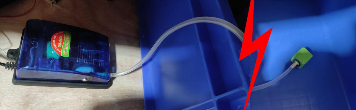
- Install an Air Pump and Air Stones: Attach an air pump to the reservoir and connect it to air stones or diffusers.
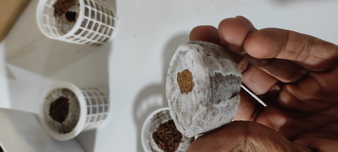
- Prepare Net Pots : Net pots are used to support the plants above the water level while allowing the roots to reach the nutrient solution.
- Monitor and Maintain: Regularly monitor the pH level, nutrient concentration, and temperature of the nutrient solution. Adjust them as necessary to ensure optimal plant growth.
- Lighting: Provide appropriate lighting to support plant growth. LED grow lights are commonly used in hydroponic systems as they are energy-efficient and provide the necessary light spectrum for photosynthesis.
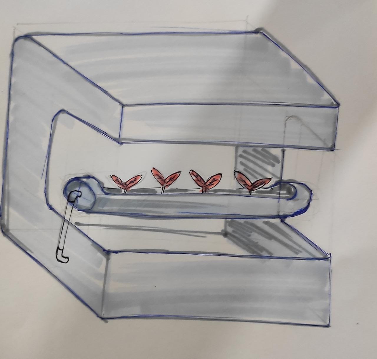
Design 2
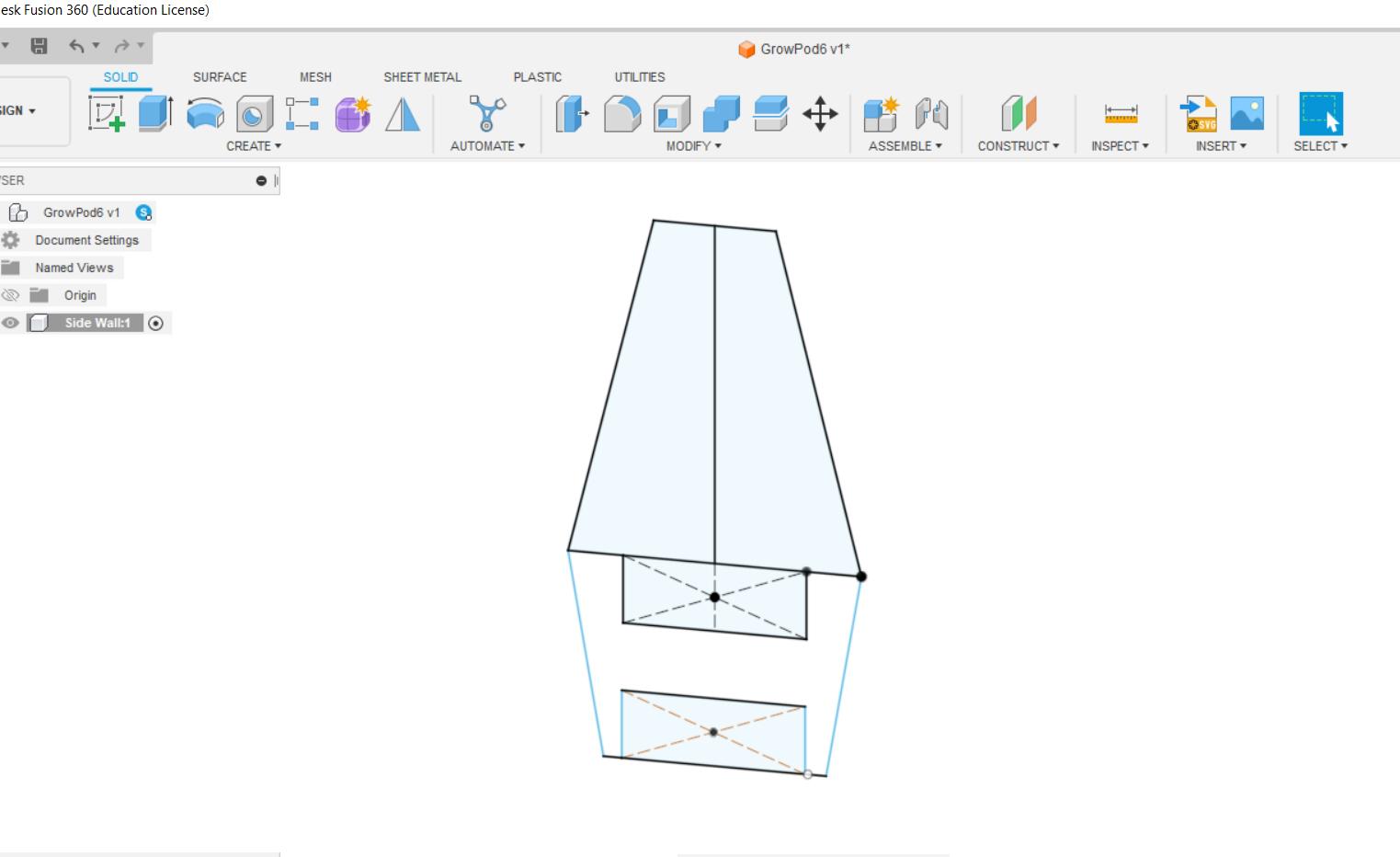
I thought of making The pod using all acrylic body the above design follows the same concept
I started designing the same on fusion 360 . While on the design i realize that we Did not have enough acrylic to fuel my concept and the procurement may be delayed .
☹️
Since the entire design was based on acrylic I had to modify the entire concept . what we had was a lot of plywood . so i thought of converting the design to make it suitable to manufacture on plywood .
Redesigning the concept 💨
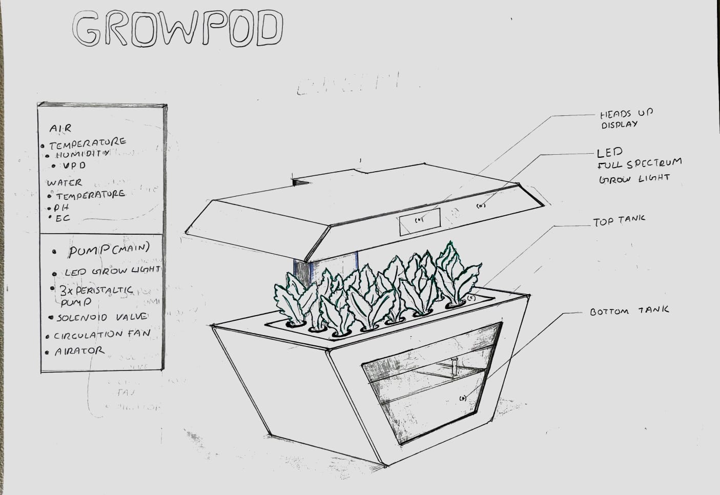
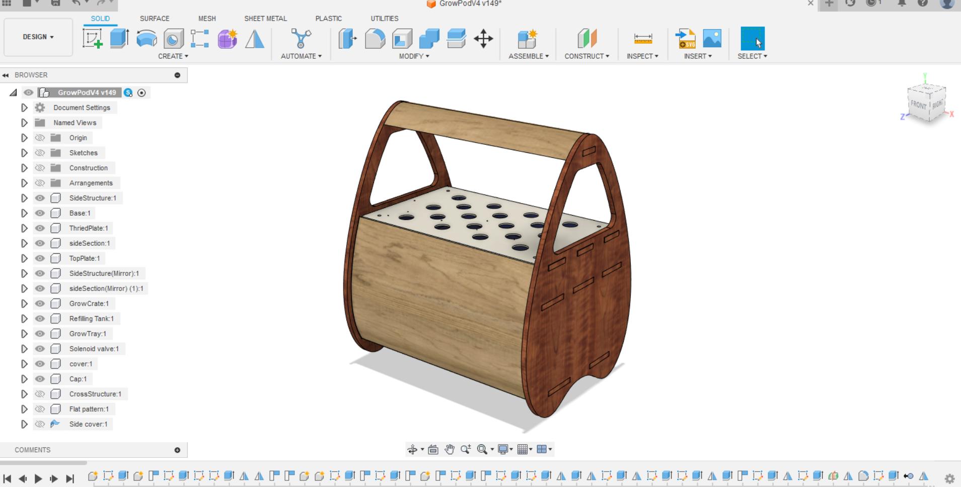
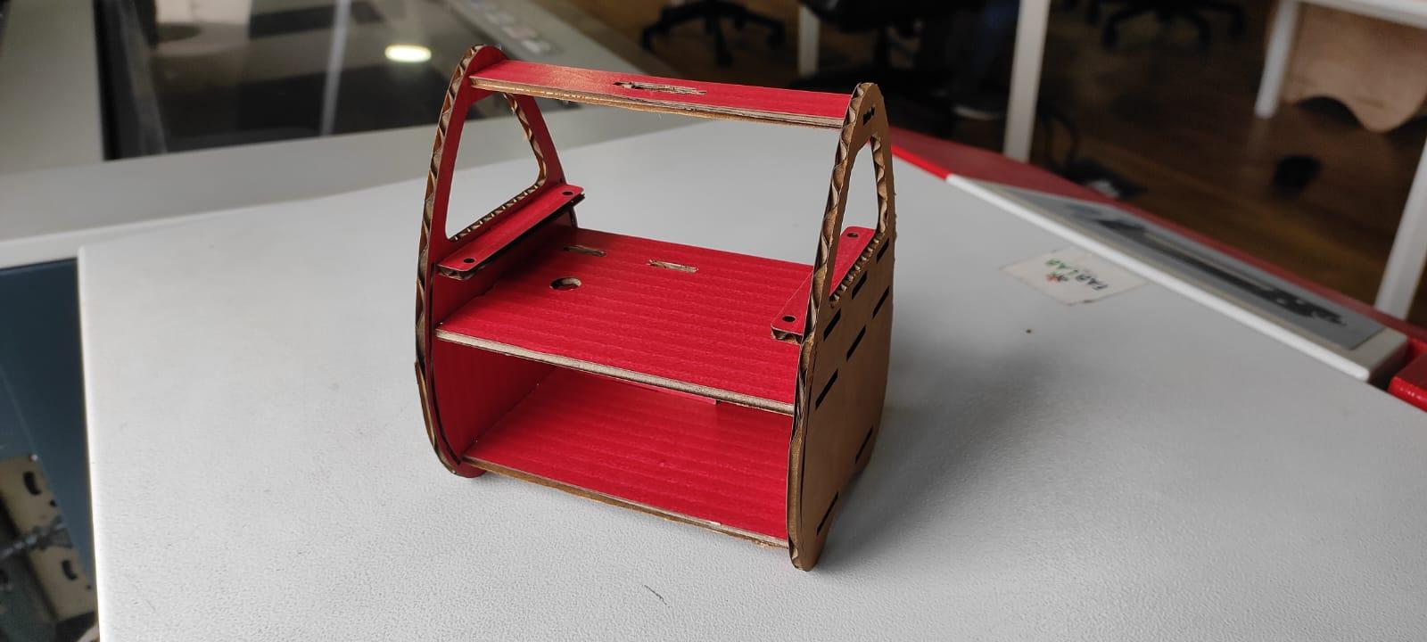
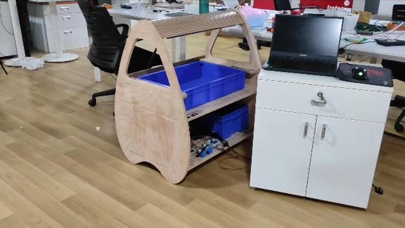
After a series of brainstorming sessions and drawing inspiration from various design elements, I ultimately sketched a design that resembled the graceful shape of a teardrop.💧.
Before Finishing the sketch design I started the 3d design simultaneously multitasking between them to make up for the lost time in the 1st design .
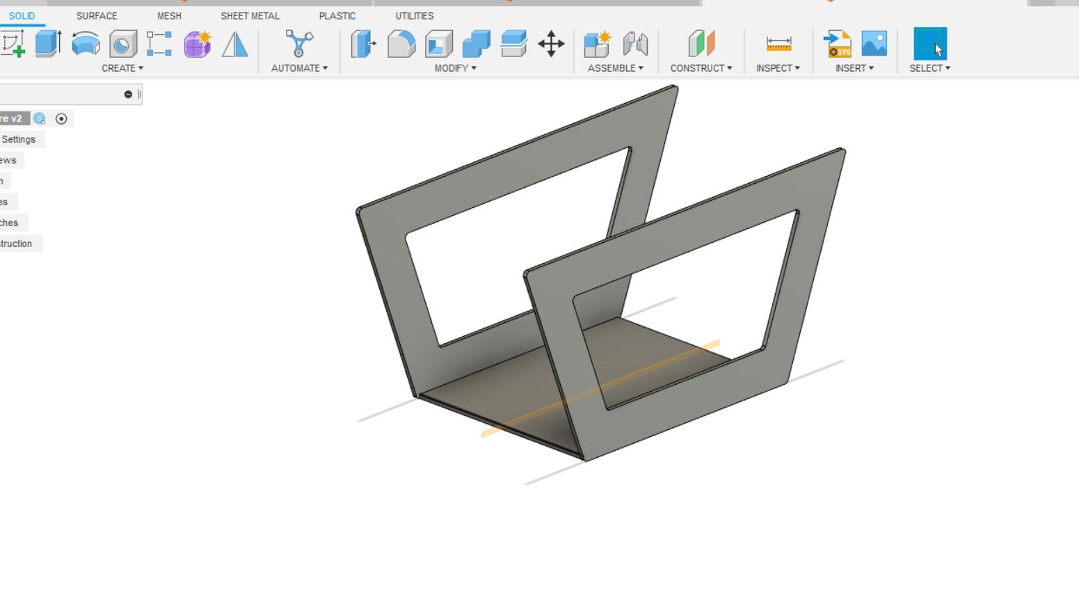
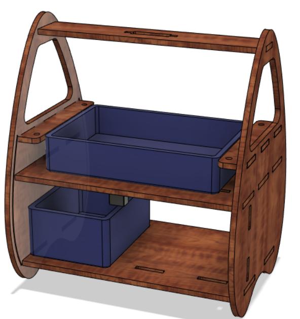
Workable 3D design
In computer controlled Machining i had already completed and Documented the Design assembly of the Tear drop Structure .
Please follow the below link for its documentation .
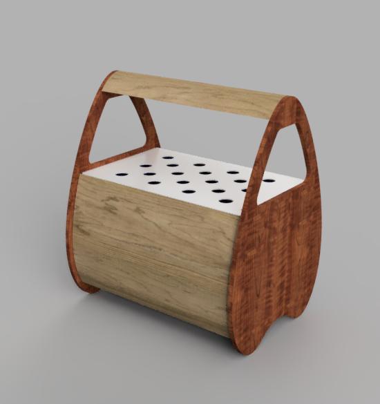
The Final Render
Manufacturing the structure
Click Here for BOM (Bill of Materials)📩
Cutting the Design on Shopbot
https://fabacademy.org/2023/labs/kochi/students/sibin-ks/assignments/week07/video5.mp4
Assembly
Circuit Design
Below is the Sketch requirement
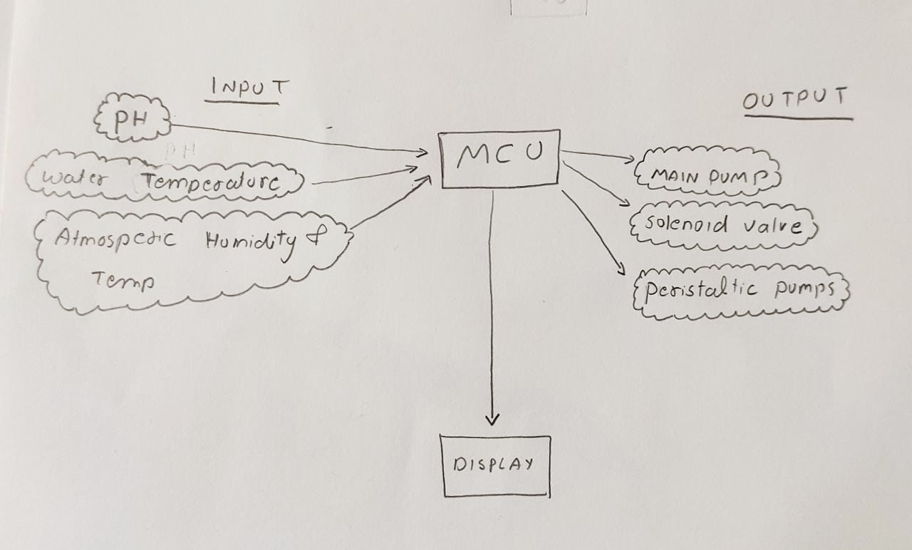
Estimating Pin requirements
Estimating pin requirements for a microcontroller project is essential because it helps determine the necessary number of input and output pins needed to interface with various components and peripherals.
Following are the Pin requirements for My project
| Parameter | Module / Sensor | Pin / protocol | Type |
| pH probe | Generic Module | 1 | Analog |
| Temperature Humidity | DS18B | 1 | Digital |
| Atmospheric Temp and Hum | SHTC3 | -I2C | SCL , SDA |
| Display | OLED | -I2C | SCL , SDA |
| Main Pump | Relay | 1 | Digital |
| Peristaltic Pump 1 | MOSFET | 1 | Digital |
| Peristaltic Pump 2 | MOSFET | 1 | Digital |
| Peristaltic Pump 3 | MOSFET | 1 | Digital |
| Solenoid valve | MOSFET | 1 | Digital |
| Rotary encoder | Encoder | 2 | Digital |
| Float Switch | switch | 1 | Digital |
Total number of digital pins required = 9
Total number of analog pins required = 1
i2C is required
wifi is required ( am planning to connect the system to node red for data logging and controls future prospect)
Selecting Microcontroller
After a inventory assessment, I confirmed the availability of the ESP32 microcontroller, which perfectly aligns with my project requirements. Therefore, I decided to choose the ESP32 as the controller for my project.
Data sheet Click here for ESP32 data sheet.
Pinout diagram of ESP32
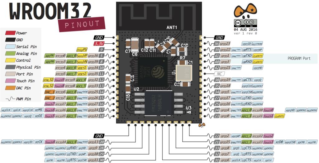
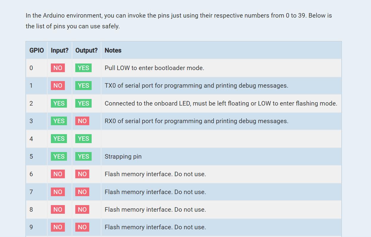
Our technical advisor, Saheen, shared a comprehensive documentation on ESP32 from circuit state that provided detailed information about the availability of pins and more .
Click here for documentation .
The documentation has elaborated the safe pin usage of ESP32 which was very useful for determining the appropriate pins for my circuit .
Powering the controller and other peripherals
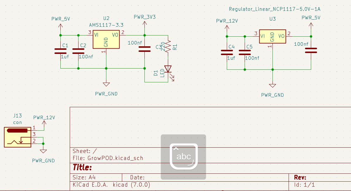
To supply the necessary power for the circuit, I employed two linear voltage regulators. Given that the circuit required three different voltage potentials, I provided an input of 12V. The AS1117 3.3 regulator was responsible for generating the 3V rail, while the AS1117 regulator was utilized to produce the 5V rail.
Below
Power switches
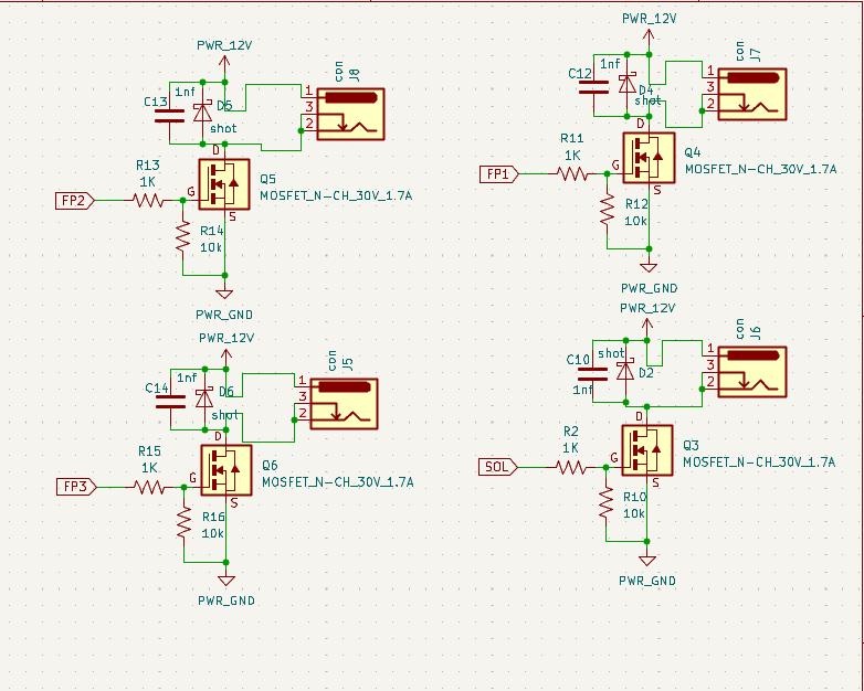
For switching the Solenoid valve and the peristaltic pump I used 1.7 amp N channel MOSFETS
Autoprogram and reset circuit
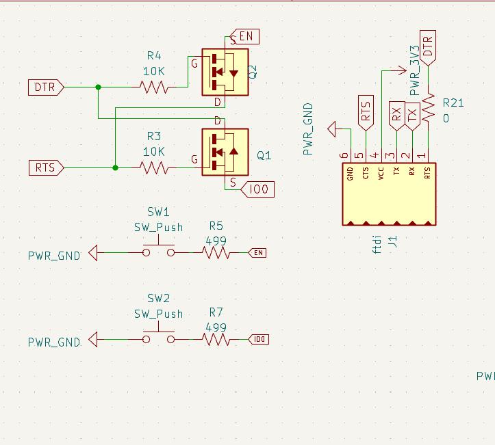
I used the same circuit to antiprogram the microcontroller .Additionally I have provided the manual switch as well.
To know more about auto program refer Week 14 > Auto program and reset
Completed Circuit
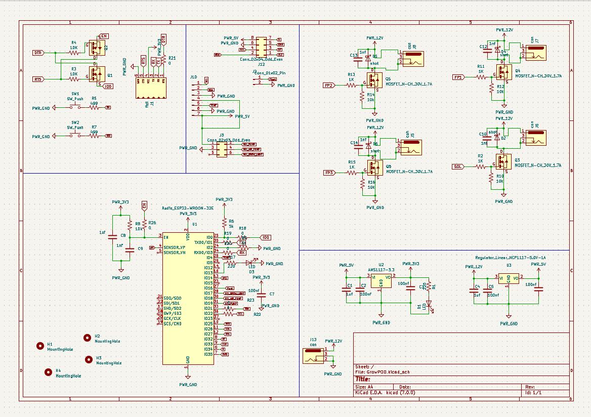
Most of the components was selected from the kicad Fab library
For power connectors I used a Mini DC Jack
To know more about Circuit and PCB refer week 06
PCB design
Given that it was the largest design I worked on during my time in the fab academy, completing the PCB design required my undivided attention for an entire day. This involved tasks such as routing and rerouting arranging components, and ensuring everything was in its proper place.
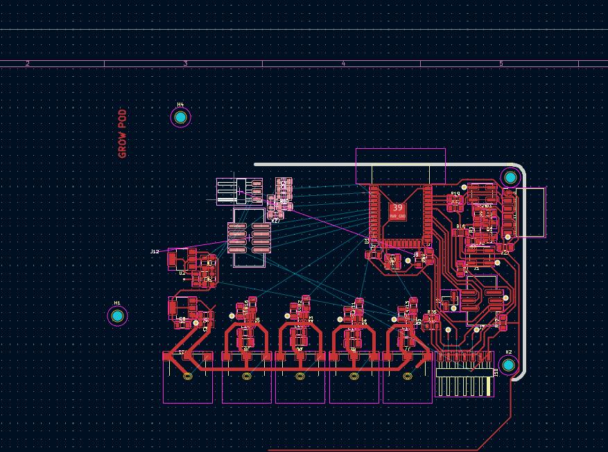
As I encountered difficulties with the design, our instructor, Jogin, suggested an alternative approach. He advised me to create the PCB on a double-sided board, designating one side specifically as the ground plane and connect both sides using vias.
Finished PCB design
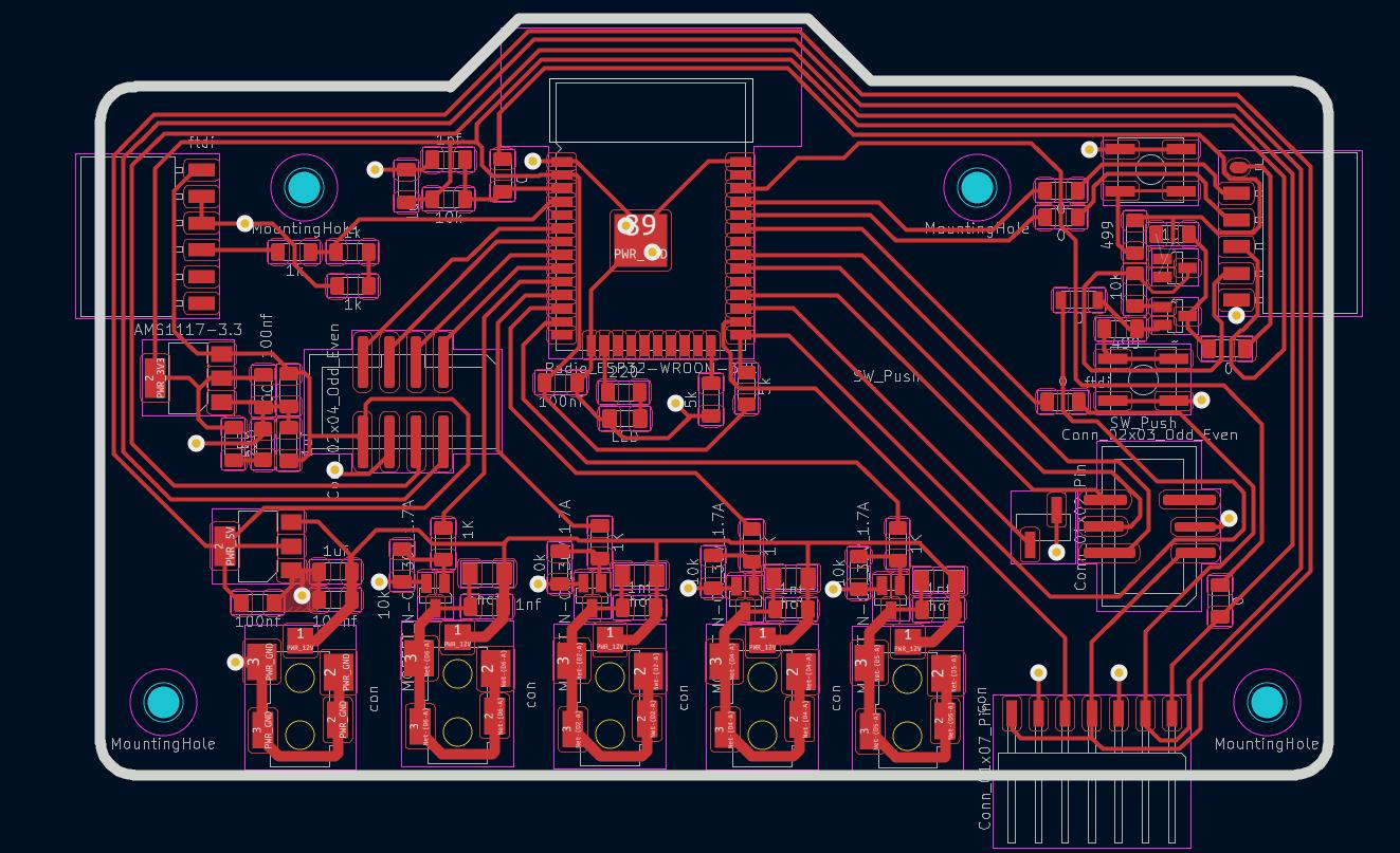
Following is the ESP32 Pin mapping for Grow Pod project
| Function | PIN number |
| Solenoid Valve | 26 |
| Peristaltic pump 1 | 27 |
| Peristaltic pump 2 | 14 |
| Peristaltic pump 3 | 25 |
| Encoder A | 32 |
| Encoder B | 33 |
| Grow Light | 28 |
| Main Pump | 31 |
| Air Pump | 30 |
| DS18B Temp sense | 26 |
| Float Switch | 27 |
| SCL | 36 |
| SDA | 33 |
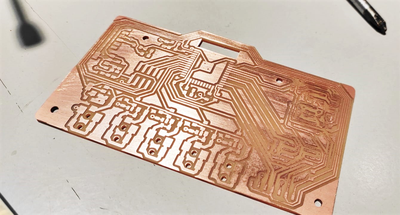
PCB Milling
I used Modela PCB Mill in our lab to mill out the pcb . since the pcb was
Final PCB Hero Shot
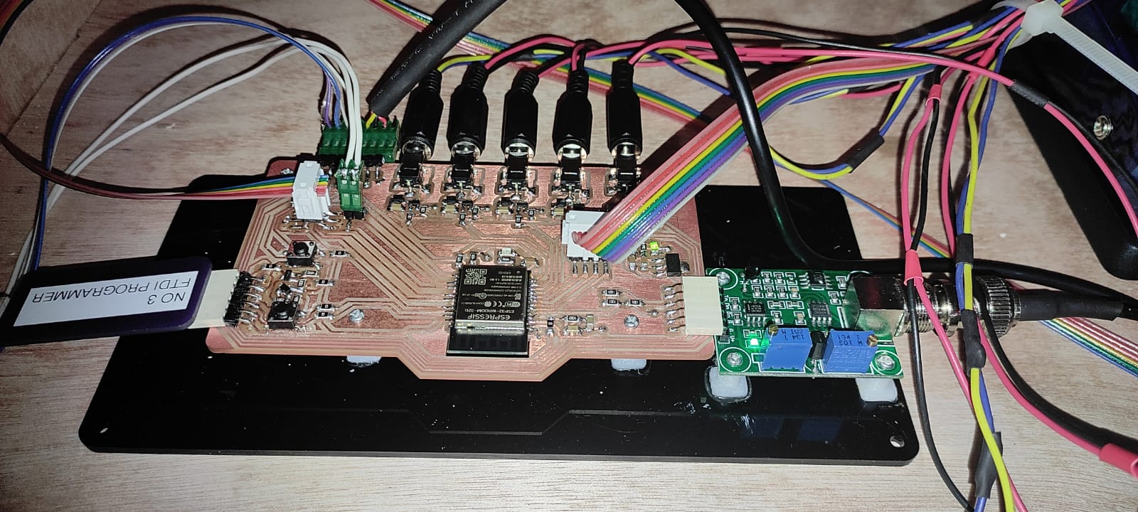
PCB assembly and Fabrication
Along with assembling the PCB I soldered the connectors to all the sensors
Below is the final hero shot of the PCB after soldering
On the right side is the pH sensor board, connected to the main board using header connectors. I positioned the connectors to enable easy installation, resembling a plug-and-play module.
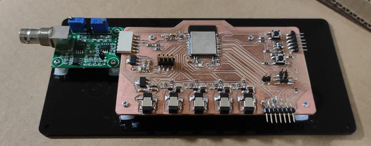
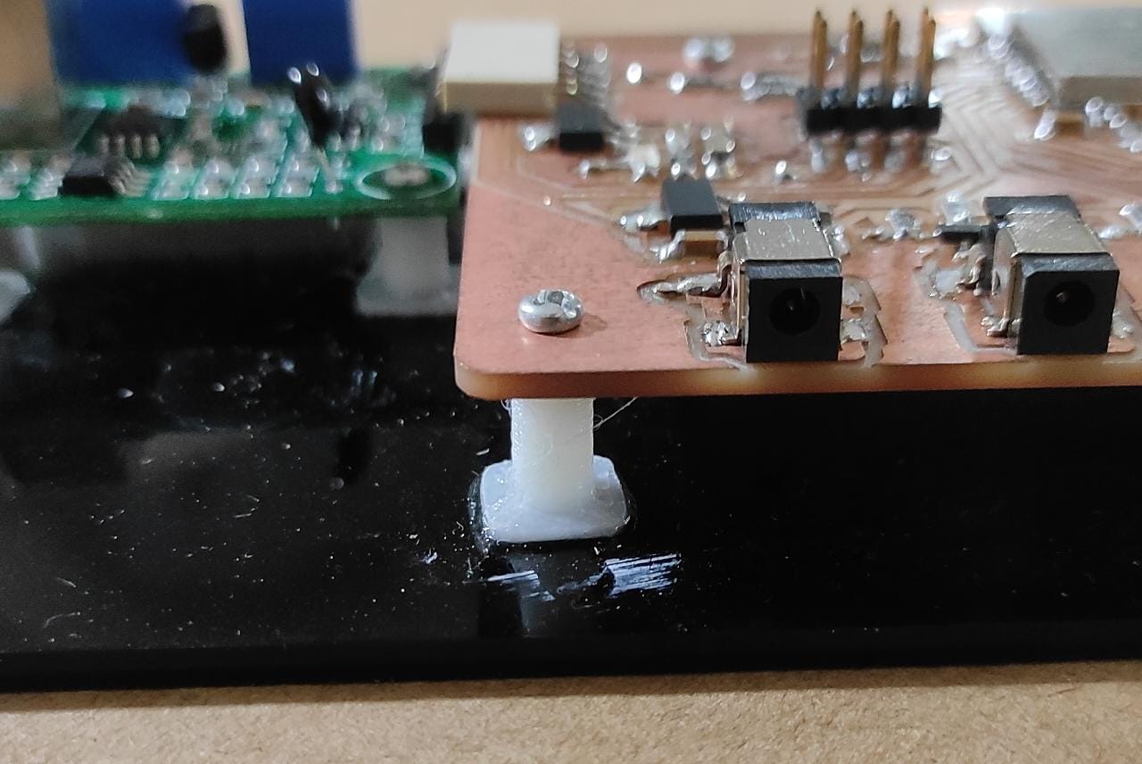
Additionally I 3D printed support mounts / stand offs for the PCB to secure the PCB to a Laser cut acrylic BASE .
Following is the connector Mapping of PCBN
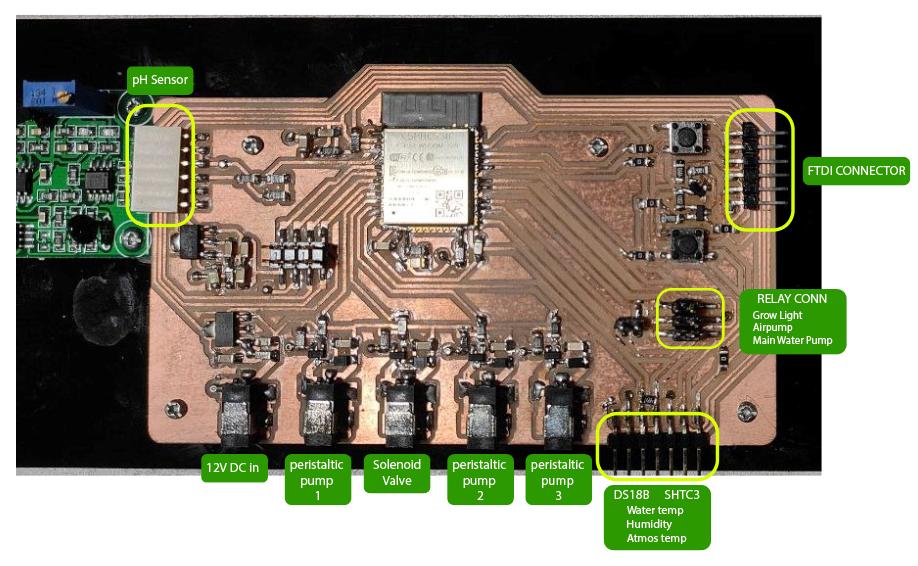
PCB testing
To ensure reliability, I tested each wire and connection using a multimeter in (conductivity buzzer). Since I utilized a ribbon cable, which is susceptible to disconnections, it was crucial to verify the connectivity of every module and sensors.
Testing PCB Pin functions by programming
I thoroughly examined the pin mappings by programming the ESP32 and confirmed the functionality of all sensors and modules. I accomplished this by printing the data on the serial monitor to ensure that everything was operating as expected.
Installing the Pipe network and Solenoid valve
To securely mount the solenoid valve at the bottom of the mid plate, I utilized 2 two 3d printed standoffs. These standoffs were designed to hold the solenoid valve in place.
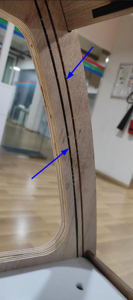
Assembling the Grow light
Grow light is assembled by properly securing and guiding the wire through the channel milled on the tear drop structure .
Installing the Top Cap with Display
Myself Together with Ajith assembled the CAP. The assembly process required two people as the two sides needed to be aligned while holding the MDF kerf bend in its bent position. This ensured proper alignment and a successful assembly.
.jpeg)
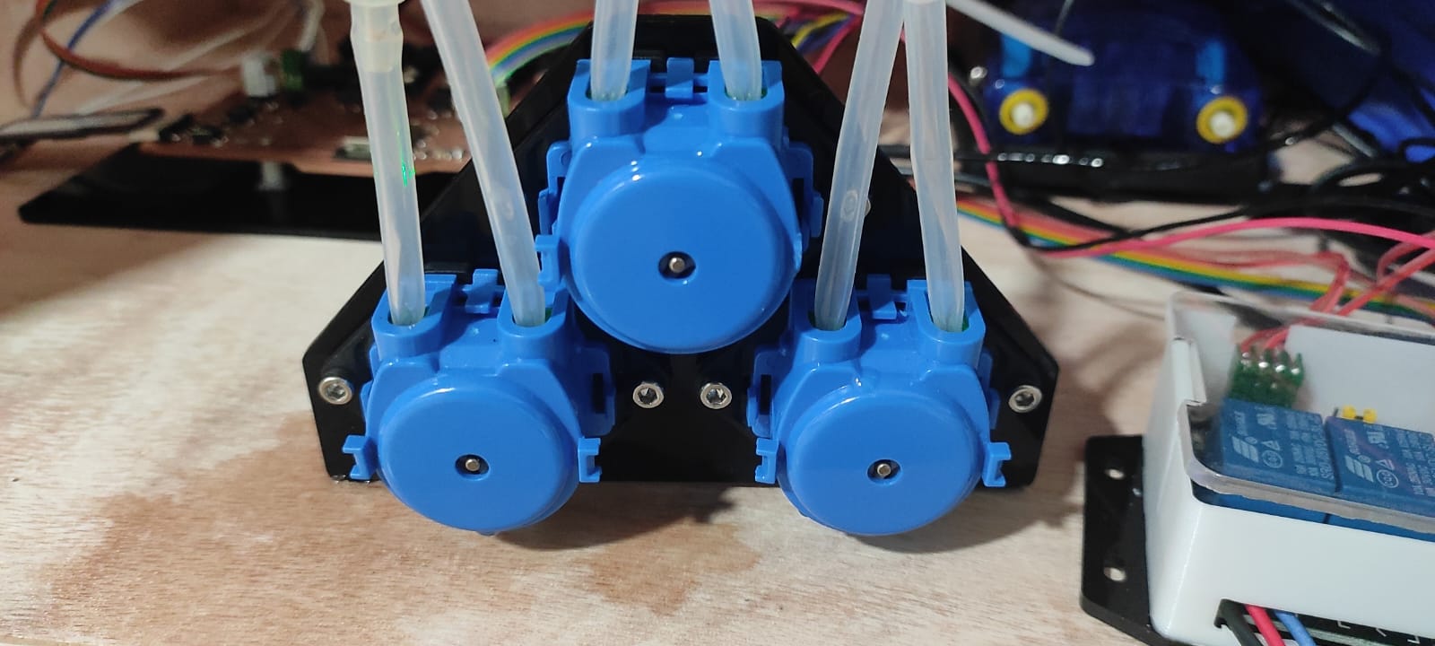
Peristaltic pumps were Fitted on a laser cut stand off Fixture
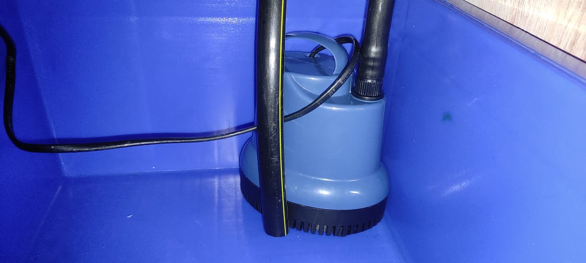
Main submersible pump which pumps the nutrients to the top tank is placed is placed on the bottom tank . The pump has a discharge of over 1500 L/ Hr
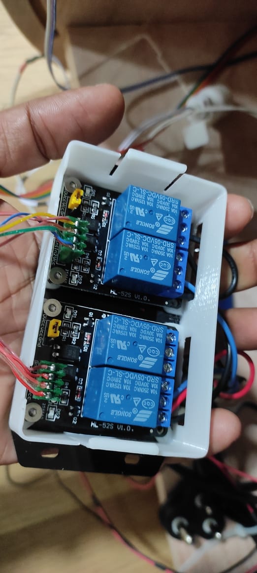
I used two relay Modules to turn ON/OFF Airpump , Grow Light Tube and Submersible Pump
Airpump was placed on the base with its Diffuser inside the bottom tray .
Wiring The system
The cable management in the setup was quite disorganized as I hadn't adequately planned for it. While I used cable ties to secure the wires, it was clear that proper cable management channels were needed for a more organized solution.
Programming
To program the pod I kept my laptop adjacent to the POD since the programing wire length was limited .
Programming The Grow light
In order to replicate natural day and night cycles, the grow light requires programming to simulate varying light intensities throughout the day. Additionally, to ensure timing, I will have to implement a real-time clock (RTC) program on the ESP32 microcontroller. This will enable precise control over the lighting schedule, allowing plants to receive the appropriate amount of light at specific times for optimal growth.
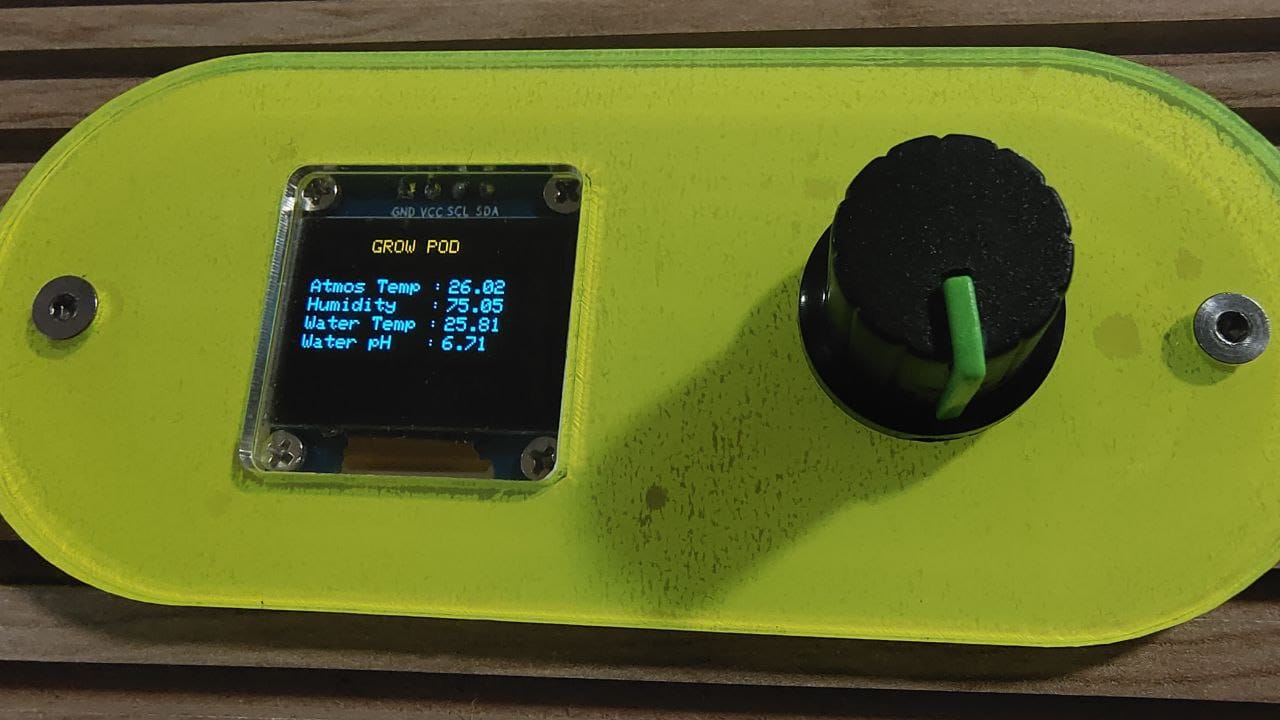
Display showing readings and status
.jpeg)
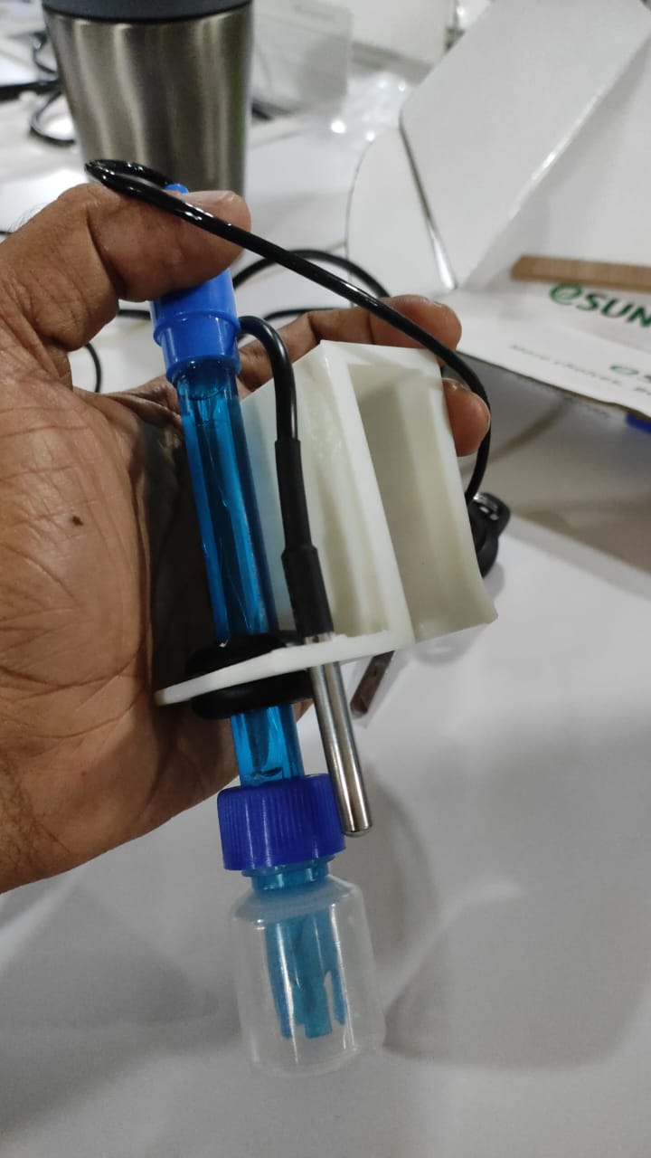
Placing the pH probes
I 3d printed a Mount for the pH and water temperature probes .
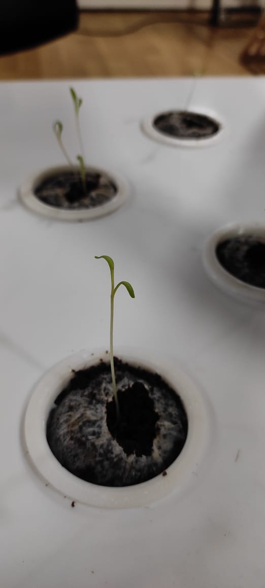
Grow Bucket and Grow Disc
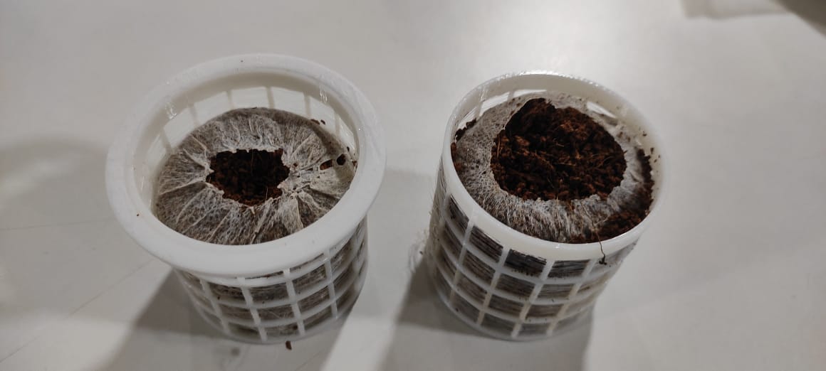
grow buckets were 3d printed with collar separately for manufacturing feasibility .
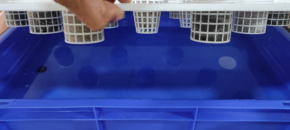
Following is a picture showing the placement of grow bucket on the Acrylic Grow tray
Conclusion
To sum up my project documentation, it is clear that there is a need for significant adjustments and improvements in the software component of the grow pod. The software requires further refinement . Moving forward, I am enthusiastic about the opportunity to further refine and enhance the system in the future .
Presentation Slide and Video
Resources and Downloads 📩
Click Here for BOM (Bill of Materials)📩
📩 All Arduino Sketches📩 Kicad project file PCB and Schematic
📩 GrowPOD fusion file