WEEK 14 - Interface and application programming
- write an application that interfaces a user with an input &/or output device that you made.
👉 Group assignment:
- compare as many tool options as possible.
👉🏼 Click here for group assignment page
-
Table of contents
Interface and Application ?
Interface is a point of interaction between two different systems, such as a user interface that allows a person to interact with a computer program, or an application programming interface (API) that allows one software program to interact with another. This week, we plan to create an application interface that will establish communication with one of our hardware boards, facilitating the exchange of data and interactions between the two systems.
Plan for this week !
During one of my previous IoT projects, I had attempted to explore Node-RED, but was unable to fully complete my exploration. However, for this assignment, I have decided to use Node-RED as my tool of choice.
I plan to establish an interface between a microcontroller and Node-RED, enabling the utilization of dashboard tools and widgets while also promoting ease of use and exploration.
Raspberry pi !
 https://www.raspberrypi.org/

Hardware!
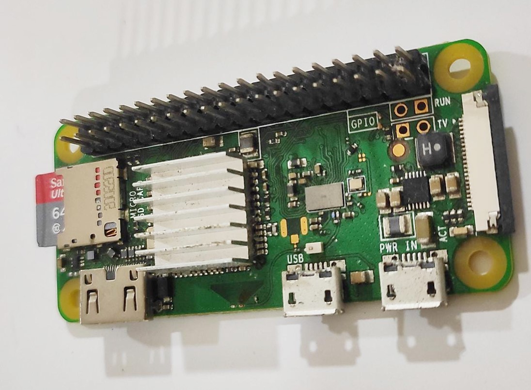
I had a Raspberry Pi Zero lying idle for some time, so I decided to repurpose it as a host for my Node-RED platform.
follow the link to learn more about raspberry pi .
Raspbian OS ? 😲
Raspbian is a free and open-source operating system (OS) designed specifically for the Raspberry Pi single-board computer. It is based on the popular Debian GNU/Linux operating system and is optimized for the ARM architecture used by the Raspberry Pi's processor.
We need to install Raspbian on our pi to make it possible to install node-red.
Follow the documentation to install Raspbian on any raspberry pi devices.

Installing Rasbian on raspberry pi !
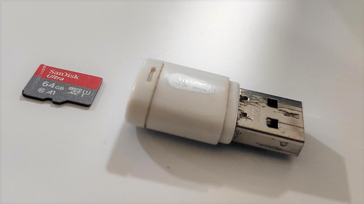
To install Raspbian OS, you will need to prepare an SD card and an SD card reader.
Follow the below link to download the raspberry pi imager software
 https://www.raspberrypi.com/news/raspberry-pi-imager-imaging-utility/

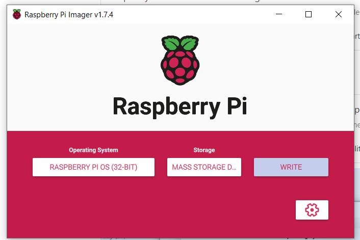
Displayed below is the Raspberry Pi Imager interface running on a Windows computer. I have selected the 32-bit Raspberry Pi OS, which is the operating system I intend to install on my Raspberry Pi Zero.
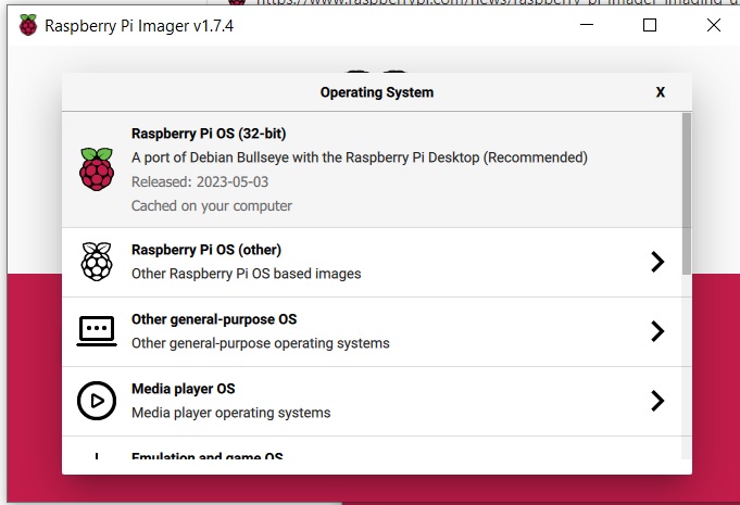
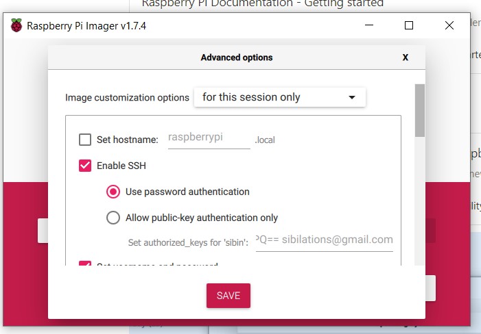
To configure location and WiFi settings, click on the settings icon located towards the bottom of the screen. From there, you can set your preferred location and WiFi network. Additionally, I recommend ticking the SSH option for future remote use.
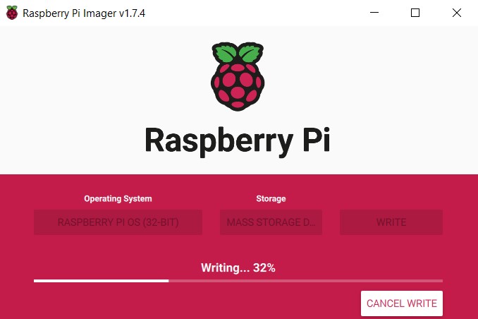
Click on the write image button to start writing the OS to the SD card .
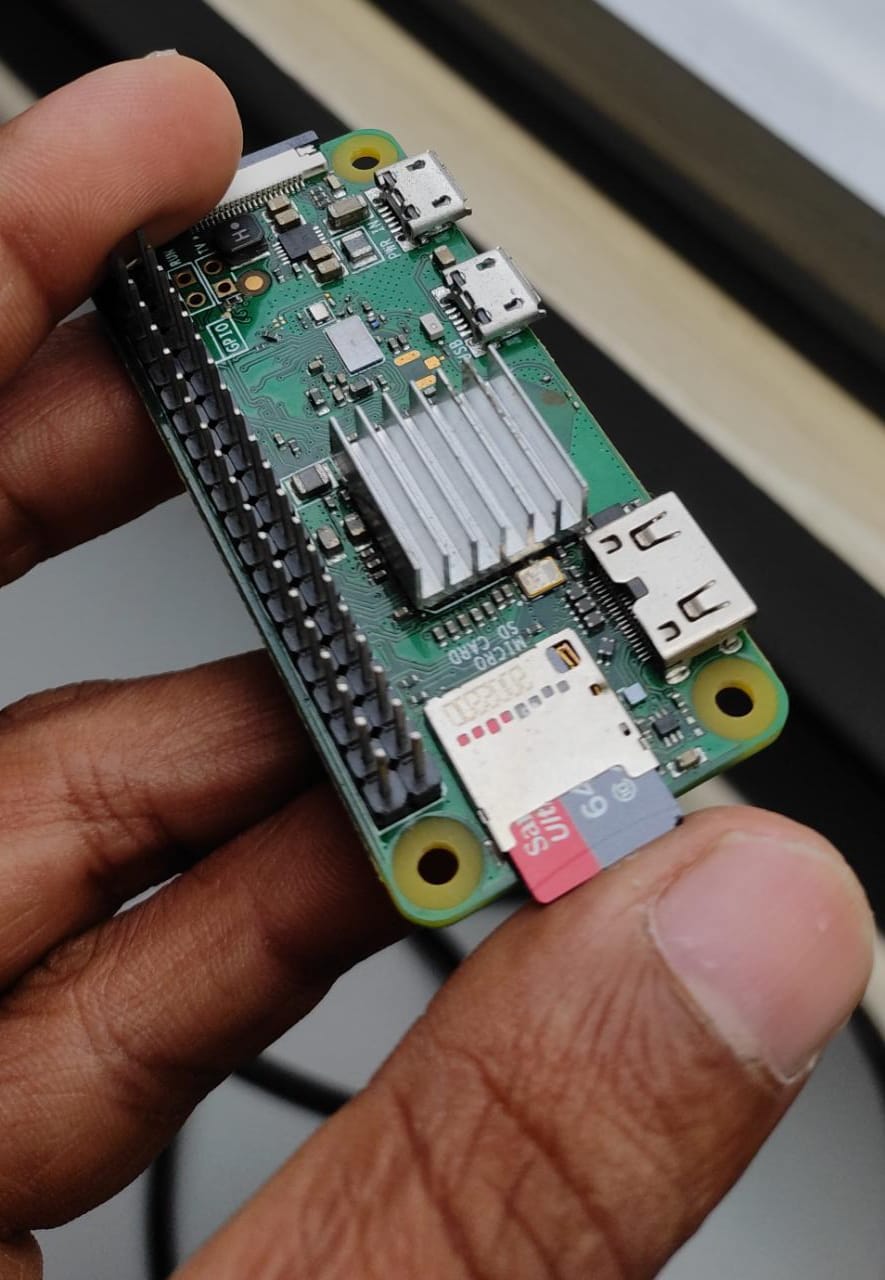
After successfully writing the image and verifying it, proceed to install the SD card on the Raspberry Pi zero, as shown in the picture.
No plug in a USB adapter with USB micro pin on the
PWR IN connector of the pi as shown in the picture .
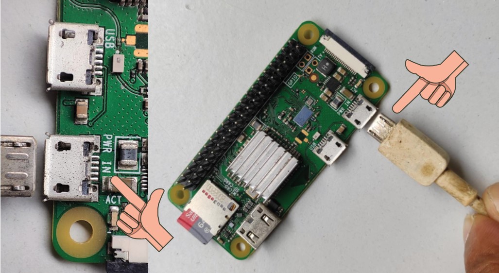
wait at least 2 minutes for the pi to boot
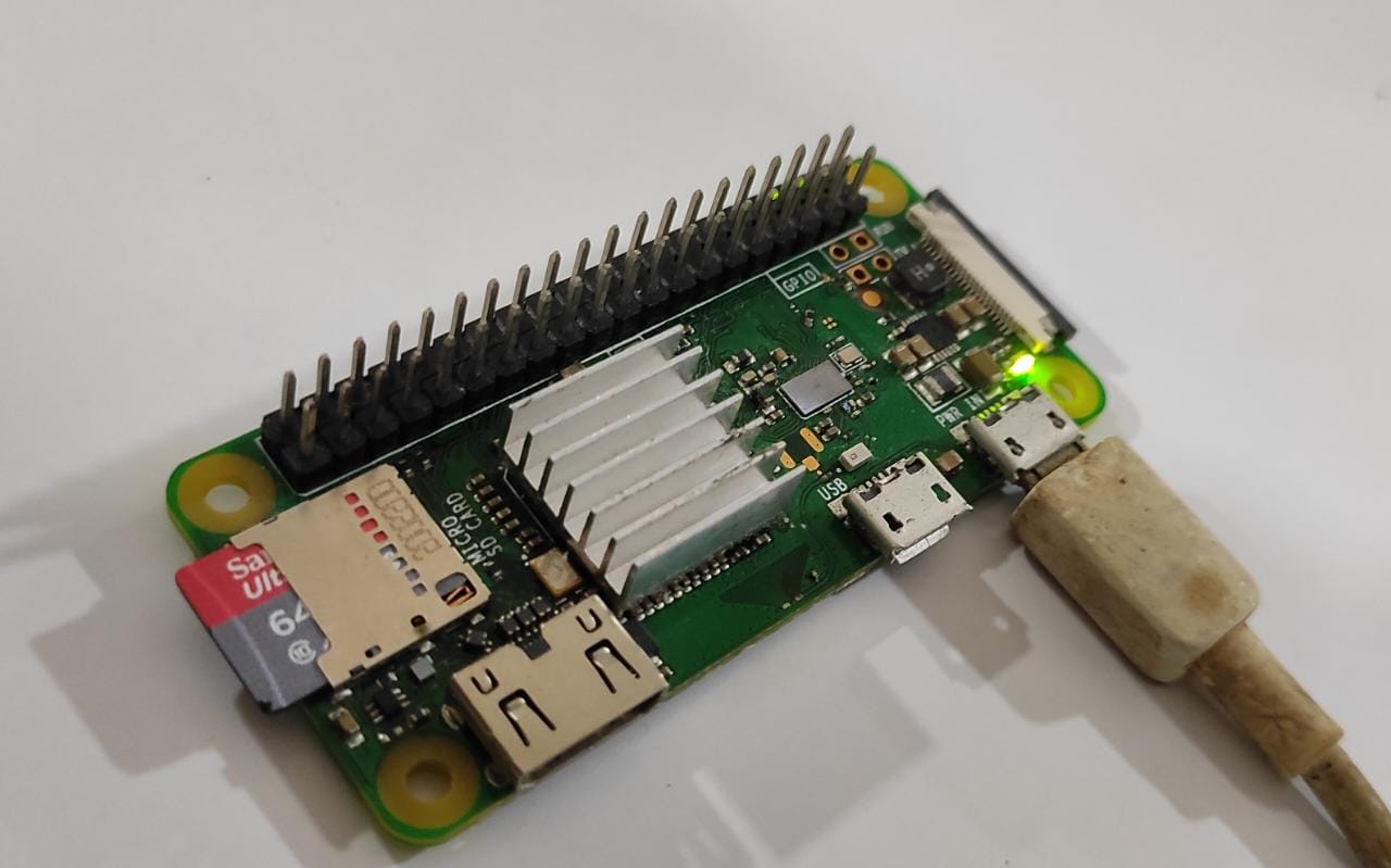
now pi should be connected to the network that was given while writing the OS .
Conform Connection
To Find whether pi is connected to the network we need to scan the network . I am using Fing on android to find the pi IP
"Fing" is a mobile app available on the Google Play Store and Apple App Store that allows users to scan and analyze their local network to discover connected devices and troubleshoot network issues
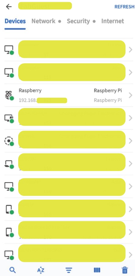
raspberry pi is listed on the network as “Raspberry” below that you can find the IP of the device .
If pi is not listed on the list refresh the list using refresh button on top right corner .
Signing in to raspberry pi on SSH
Download and install PuTTy software on your PC.
To download putty follow this link
Type in the raspberry pi IP address Host name on putty
with port 22 click OPEN .
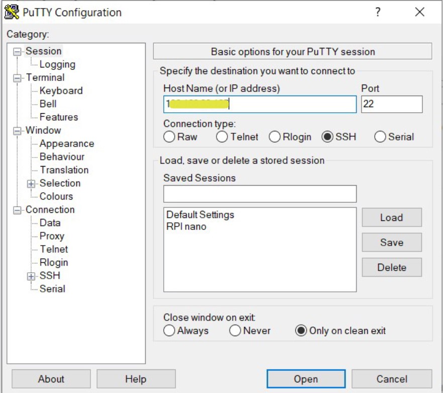
If a security prompt is displayed click yes to continue
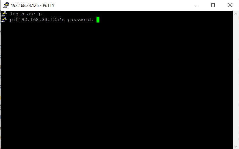
Next, you will be prompted to enter the user ID, which in this case is
"pi". After entering the user ID, you will then
be prompted to enter the associated password. After typing password
press enter
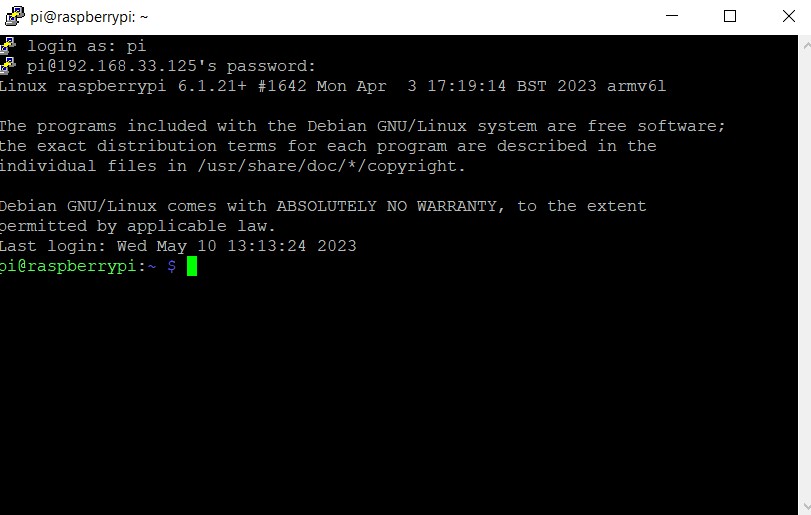
If you see the above screen, it means you have successfully logged in to the Raspberry Pi using the command line interface (CLI).
Ok now time to set up the node red on pi.
Preparing raspberry pi
Type in the following code and press enter to update and upgrade raspberry pi to the lastest version.
sudo apt-get update && sudo apt-get upgrade -y
sudo command allows a user to
execute commands with administrative privileges.
apt-get is a package manager for
Debian-based systems that allows users to install, update, and
remove software packages. The
update command updates the local
package index, which is a list of available packages and their
versions.
upgrade command then upgrades the
installed packages to their latest versions, based on the updated
package index. By running these two commands together, you can
ensure that your Raspberry Pi is running the latest versions of the
installed packages and is up to date with the latest security
patches.
What is node red ?
Installing and Configuring Node-RED on raspberry pi
Follow the below link to find documentation on how to install node red on raspberry pi.
I combined all the command to form a single line command.
sudo apt-get update && sudo apt-get upgrade -y &&
                    sudo apt-get install -y git && sudo git --version &&
                    yes | head -n 1 | bash <(curl -sL
                    https://raw.githubusercontent.com/node-red/linux-installers/master/deb/update-nodejs-and-nodered)
Copy paste the above code to install and configure node red .
👇🏼 If the above code does not work follow the bellow consolidated steps .
Following are the consolidated command steps to install node red which should be run on the ssh terminal.
1 sudo apt-get install -y git install git first
2 git --version check git version
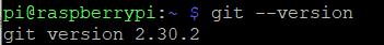
3
bash <(curl -sL
                    https://raw.githubusercontent.com/node-red/linux-installers/master/deb/update-nodejs-and-nodered)
install node js and node red
After executing these commands, you will be prompted for permission to install Node-RED. To proceed with the installation, go with "yes" .
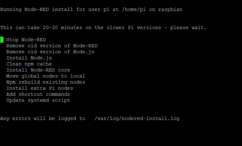
This will take a while to finish
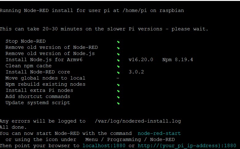
The screen displayed above is what you will see after completing the setup.
4 node-red-pi --max-old-space-size=256 is a command that
is used to start the Node-RED runtime on a Raspberry Pi device with a
specific memory allocation.
Note: installation is complete
5 sudo systemctl enable nodered.service for autostarting
node-red everytime raspberry pi reboots.
Running as a service
The install script for the Pi also sets it up to run as a service. This means it can run in the background and be enabled to automatically start on boot.
The following commands are provided to work with the service:
-
node-red-start- this starts the Node-RED service and displays its log output. PressingCtrl-Cor closing the window does not stop the service; it keeps running in the background
-
node-red-stop- this stops the Node-RED service
-
node-red-restart- this stops and restarts the Node-RED service
-
node-red-log- this displays the log output of the service
You can also start the Node-RED service on the Raspberry Pi OS
Desktop by selecting the Menu -> Programming -> Node-RED menu option.
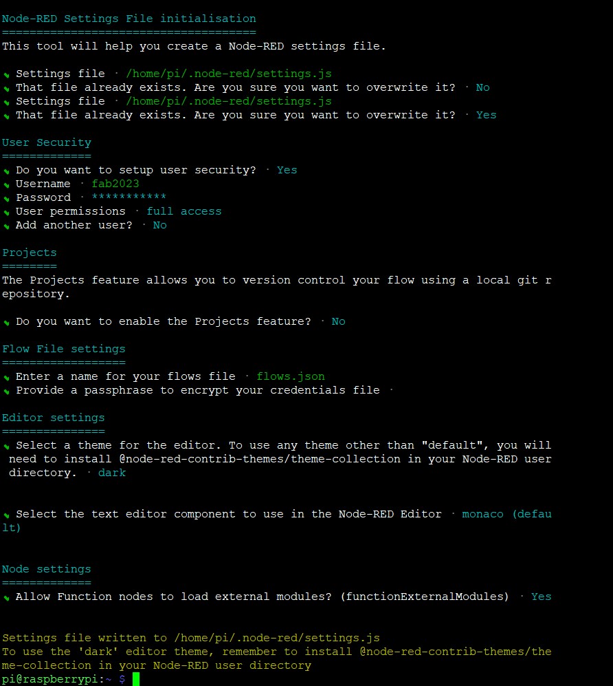
Configuring Node-Red settings
node-red admin init
run the settings wizard and add username and password.
Following are the setting that I gave
7 node-red-restart after applying all the settings
restart node red
Opening Node-Red editor on your PC
When browsing from another machine you should use the hostname or
IP-address of the Pi: http://<hostname>:1880.
You can find the IP address by running hostname -I on the
Pi.
in my case its
http://192.168.xx.xx:1880
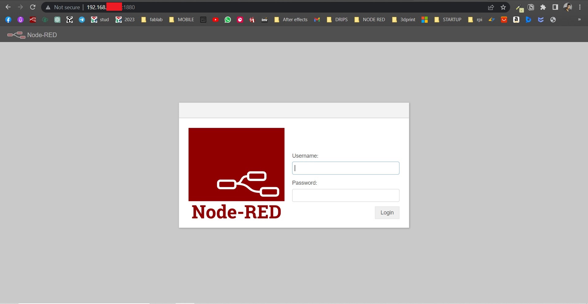
Type in the username and password and you will see the node red dashboard
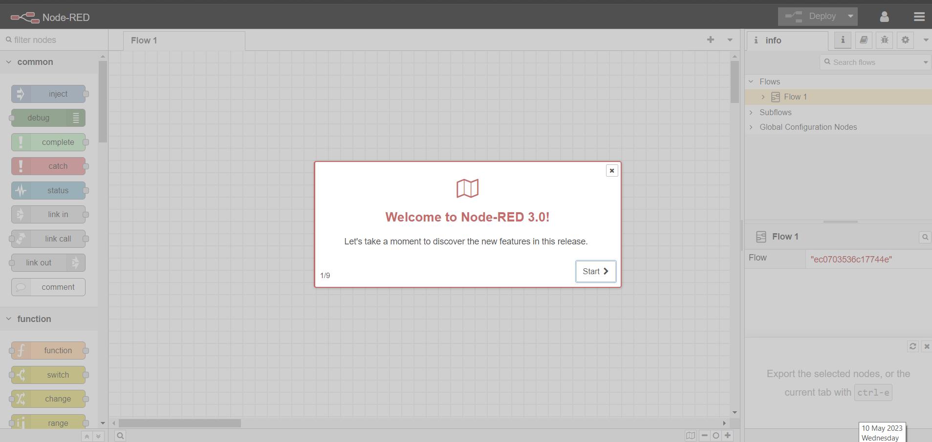
Node-red
Follow the below link to find more about node flows
Dashboard
In node red we need to install dashboard widgets
Dashboard widgets in Node-RED refer to the various graphical elements that you can add to your application's user interface. These widgets are designed to display and interact with data that is generated by your application or external data sources.
To install dashboard
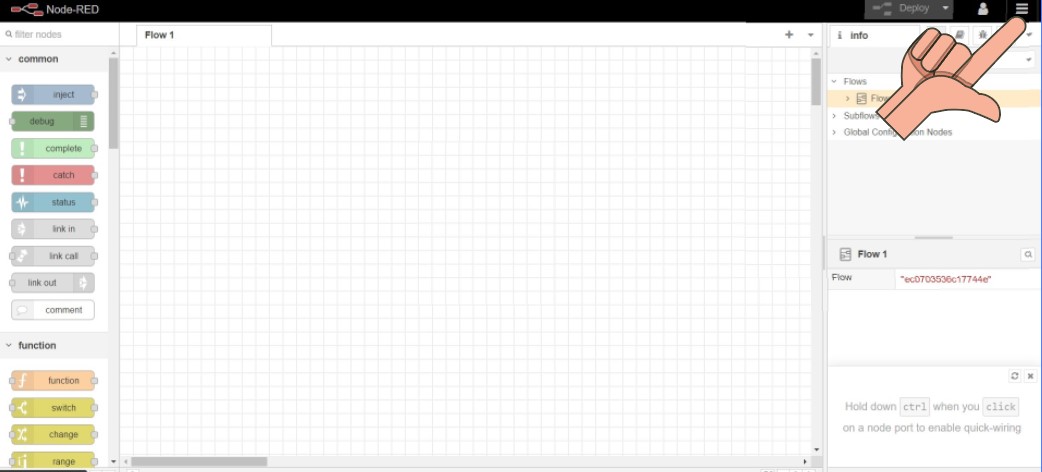
Click on the menu tab
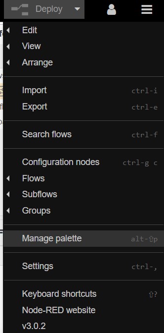
Click on Manage palette
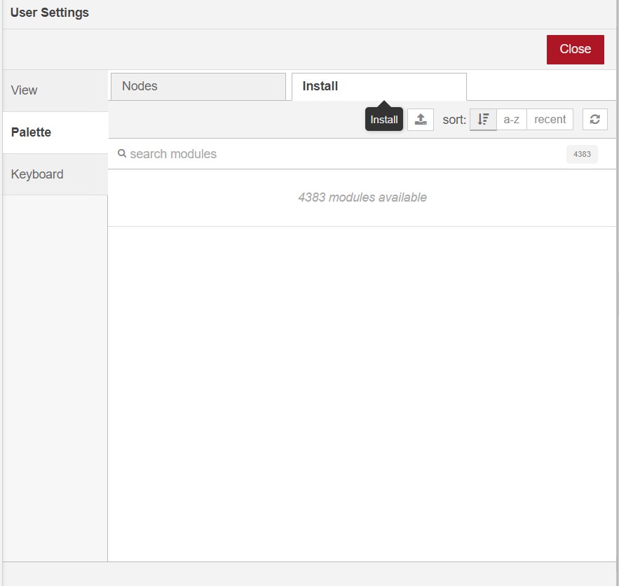
Click on install and search for dashboards
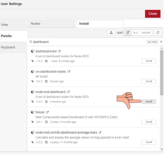
Click on node-red-dashboards and click install as shown in the above picture

When the above confirmation is prompted click on install
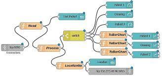
Nodes
Towards the left side of the dashboard one can see a list of nodes .
check whether dashboard nodes are available on the lists
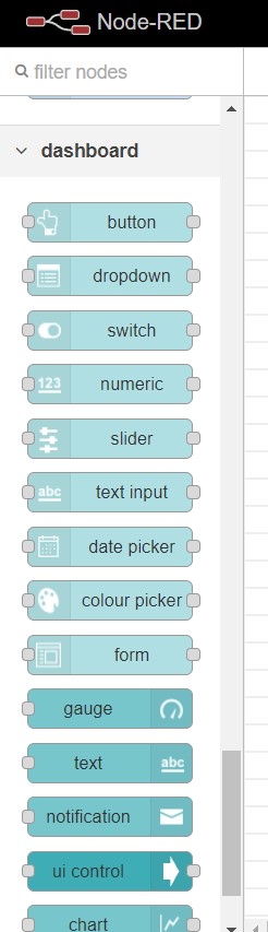
- To use a node drag it from the node palette on the left-hand side of the screen to the workspace on the right-hand side.
- Once you have added the node to the workspace, you can configure its settings by double-clicking on it. This will open the node's properties panel, where you can set parameters and options for the node.
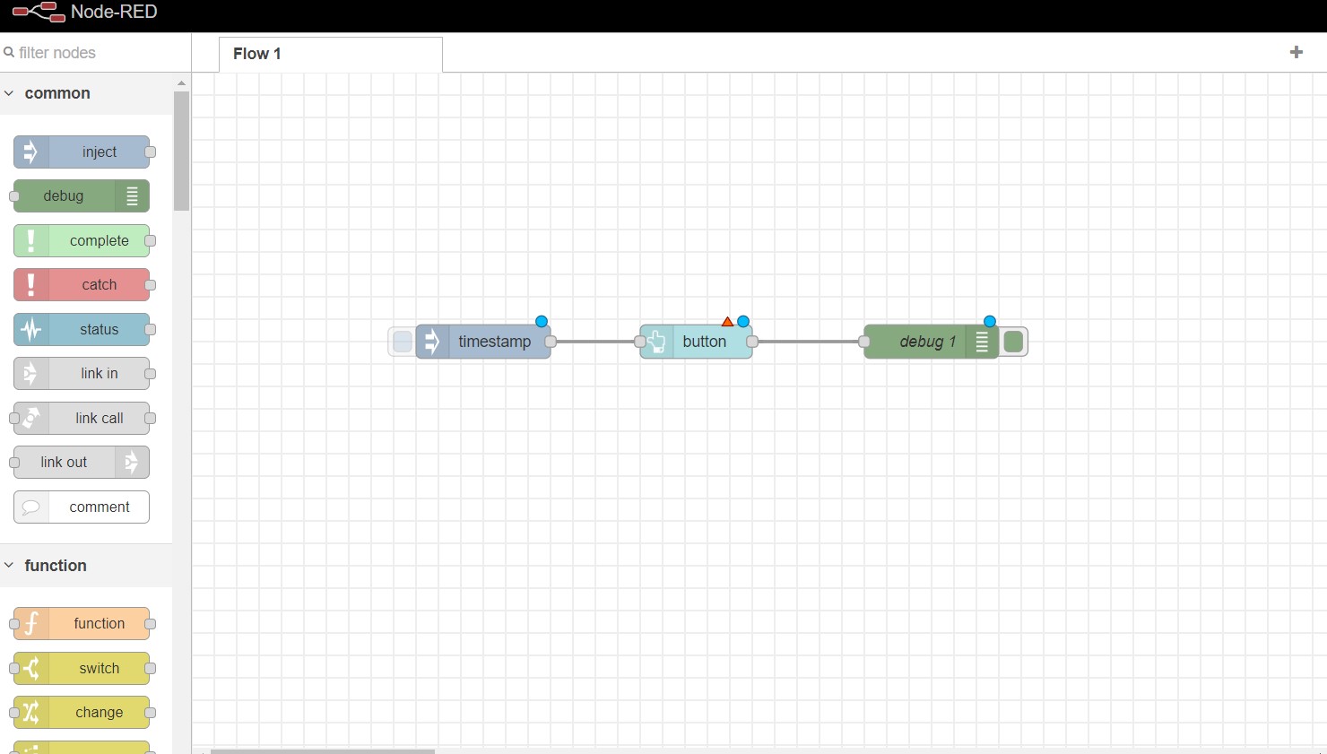
Connect the nodes together by dragging a connection line from the output of one node to the input of another.
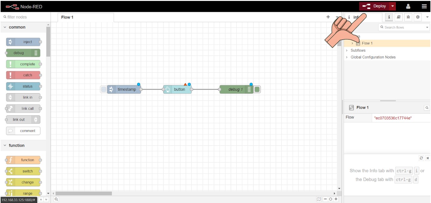
Deploy the application by clicking on the "Deploy" button in the top-right corner of the screen. This will activate the nodes and start the application.
After confirming deploy the below shown msg will be displayed .

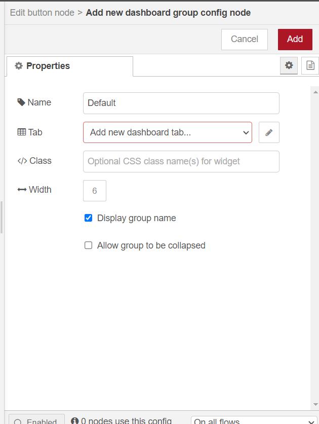
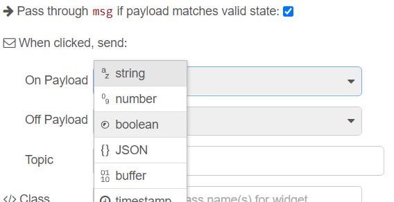
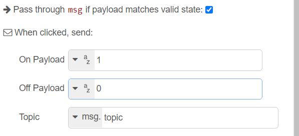
when you double click on any widget ( button for example ) you will
get a properties tab add a group by clicking on the
pencil icon next to group .
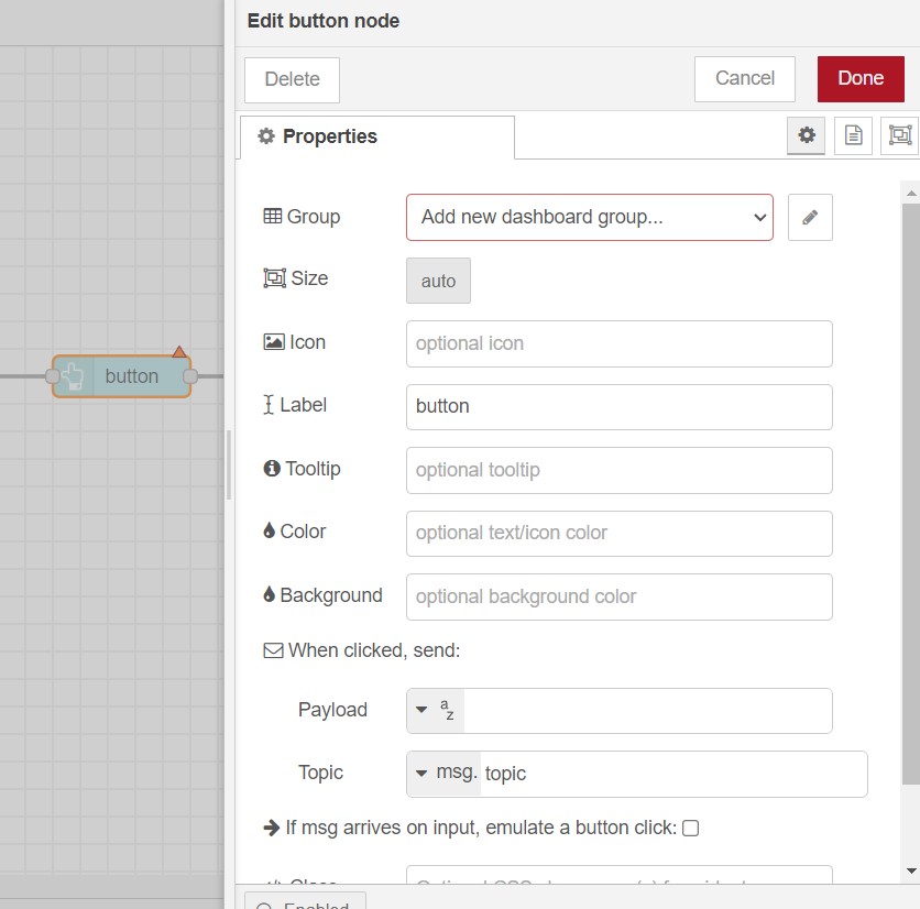
Click the Add button to add button to the dashboard .
If everything is fine then there wont be any warning signs above the widgets
Now click on the Deploy button to push the changes to dashboard
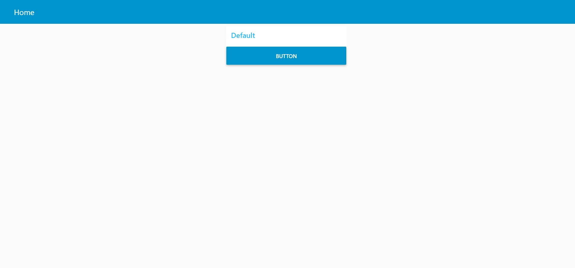
Dashboard
To view dashboard click on the below shown icon.
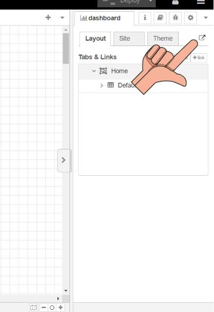
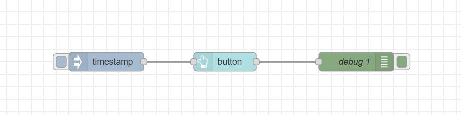
Following is the dashboard for the button that we made .
What is MQTT?
To install mqtt on raspberry use the following command .
sudo apt install mosquitto mosquitto-clients
😪 The lengthy series of challenges !
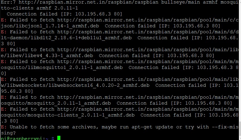
☹️ i had some errors when installing the mosquito server clients .
It seems i forgot to add the import the repository package.
After some digging I found mosquitto documentation follow the link to find the doc .
 https://mosquitto.org/blog/2013/01/mosquitto-debian-repository/
wget http://repo.mosquitto.org/debian/mosquitto-repo.gpg.key
sudo apt-key add mosquitto-repo.gpg.key
cd /etc/apt/sources.list.d/ Then make the repository
available to apt
sudo wget
                    http://repo.mosquitto.org/debian/mosquitto-bullseye.list
for other debian version use
sudo wget http://repo.mosquitto.org/debian/mosquitto-jessie.list
        sudo wget http://repo.mosquitto.org/debian/mosquitto-stretch.list
sudo apt-cache search mosquitto
sudo apt-get install mosquitto
Still Not working
sudo apt autoremove
In the end, I restarted the system, which resolved the errors that were occurring.
Update the package list by running the following command:
👉🏼 sudo apt-get update
Install the mosquitto broker by running the following command:
👉🏼 sudo apt-get install mosquitto
Install the mosquitto client by running the following command:
👉🏼 sudo apt-get install mosquitto-clients
To check the working of server paste the following command
ps aux | grep mosquitto
well in my case the mosquito server failed to install ☹️

I kept of trying different approaches to install like changing mirrors of debian repository .etc
 https://pimylifeup.com/raspbian-repository-mirror/

☹️ but nothing seemed to be working .
upon returning home and attempting the same installation process on my home network, everything worked smoothly. It appears that certain repositories may have been restricted access at our lab network .
😃 Finally back to being happy !
sudo apt install mosquitto mosquitto-clients
I used the same command at my home network and everything was back to normality .
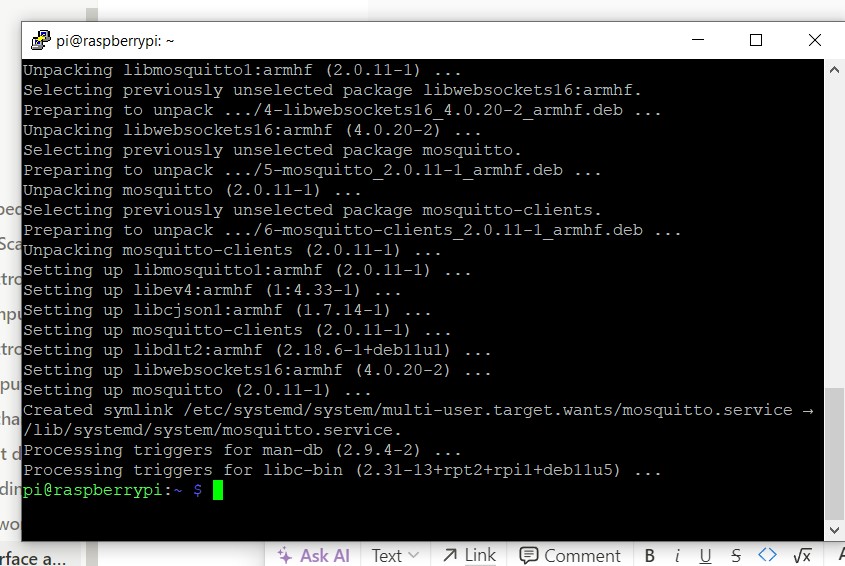
It worked 🥳
mosquitto -v
use the following command to confirm the latest version of mosquitto
broker
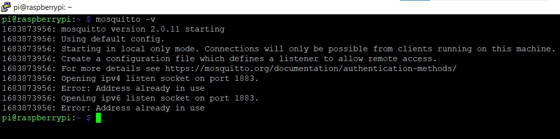
New error
There is an error showing address already in use
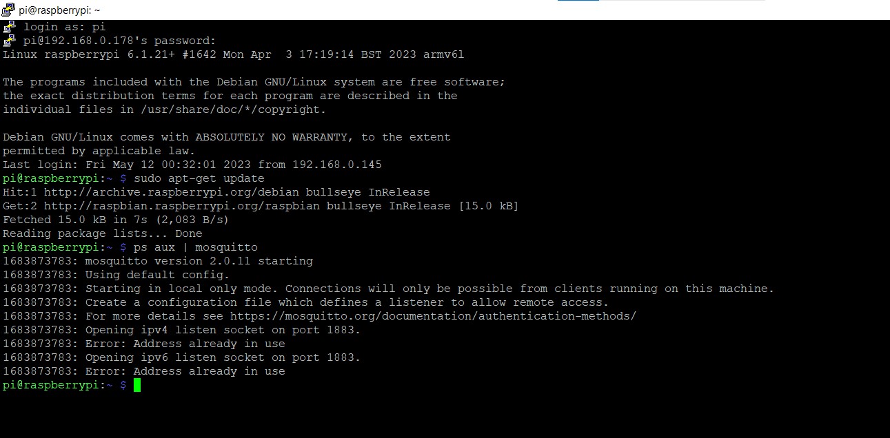
I restarted the pi and the error got cleared .
ran ps aux | grep mosquitto

running perfectly “🤗
ps aux | grep mosquitto is a command
used to search for all running processes that contain the keyword
"mosquitto" in their names.
-
psstands for process status and displays information about running processes.
-
auxare command-line options that show all running processes for all users (a) in a detailed list (u) that includes the process owner and other information (x).
-
grepis a command-line utility used for searching a given input for a pattern, and here we use it to filter out the processes that have the word "mosquitto" in their names.
So the combined command
ps aux | grep mosquitto is used to
show all running processes that have "mosquitto" in
their name.
MQTT publisher and subscriber
First terminal paste
mosquitto_sub -v -t notebook/test
mosquitto_sub -v -t notebook/test is a
command that subscribes to the MQTT topic
notebook/test and prints the messages
received from that topic to the console with verbose mode enabled.
Here's what each argument means:
-
mosquitto_sub: This is the command to start the Mosquitto subscriber client.
-
v: This enables verbose mode, which prints additional information about each received message, including the topic and message payload.
-
t notebook/test: This specifies the MQTT topic to which the client should subscribe. In this case, the topic isnotebook/test.
So when you run this command, the subscriber w
Second terminal paste
mosquitto_pub -t notebook/test -m "12345"
mosquitto_pub -t notebook/test -m "12345"
is a command that publishes the message "12345" to the MQTT
topic notebook/test.
Here's what each argument means:
-
mosquitto_pub: This is the command to start the Mosquitto publisher client.
-
t notebook/test: This specifies the MQTT topic to which the message should be published. In this case, the topic isnotebook/test.
-
m "12345": This specifies the message payload to be published. In this case, the payload is the string "12345".
So when you run this command, the publisher will connect to the MQTT
broker and publish the message "12345" to the
notebook/test topic. The message will be
sent to the broker, and any subscribers that have subscribed to that
topic will receive the message.
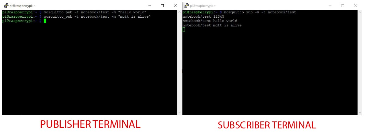
likewise I send
mosquitto_pub -t notebook/test -m "hallo world"
and
mosquitto_pub -t notebook/test -m "mqtt is alive"
Time to add some layer of Security to Mqtt
After reviewing the information provided at https://mosquitto.org/man/mosquitto-conf-5.html, I have found all the essential directives for implementing security measures.
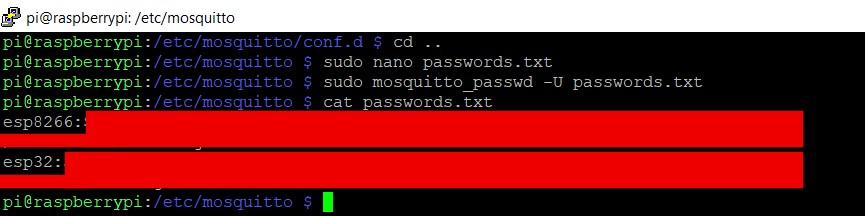
cd /etc/mosquitto/conf.d go to the mosquitto directory .
sudo nano mosquitto.conf make a file
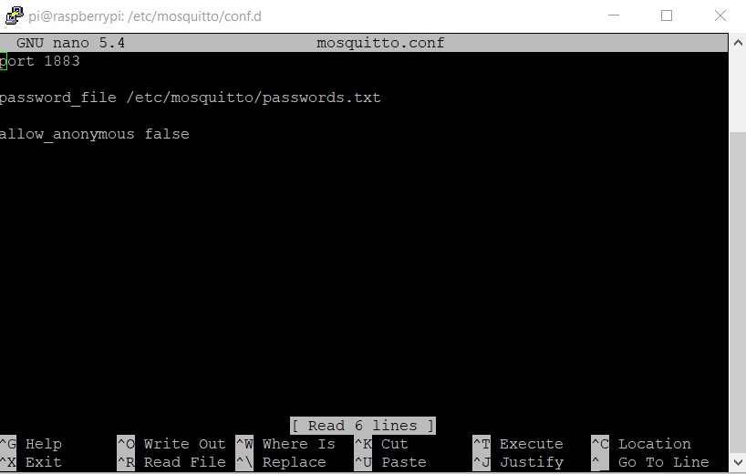
port 1883
        password_file /etc/mosquitto/passwords.txt
        allow_anonymous false
after saving the file
come back to cd /etc/mosquitto ( by clinking cd .. )
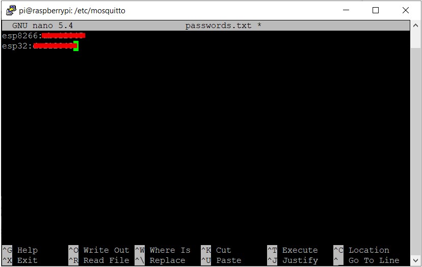
sudo nano passwords.txt make a file passwords.txt
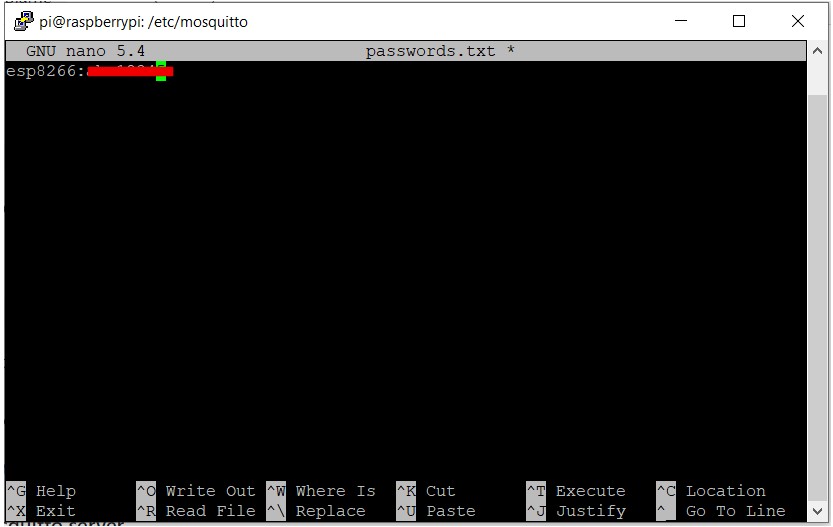
where esp8266:xxxxx is the client and
xxxxx is the password .
we can have as many user name and passwords as we want.
to encrypt the file use the following command.
sudo mosquitto_passwd -U passwords.txt
-
sudo: This runs the command with administrative privileges.
-
mosquitto_passwd: This is the command to manage the Mosquitto password file.
-
U: This updates the password file specified in the argument.
-
passwords.txt: This is the name of the password file to be updated.
cat passwords.txt
you can see the username followed by encryption
MQTT publisher and subscriber with authentication
Subscriber
mosquitto_sub -u esp8266 -P ******** -v -t notebook/test
Publisher
mosquitto_pub -u esp8266 -P ******** -t notebook/test -m
                    "hallow world"
follow “MQTT publisher and subscriber” above for reference .
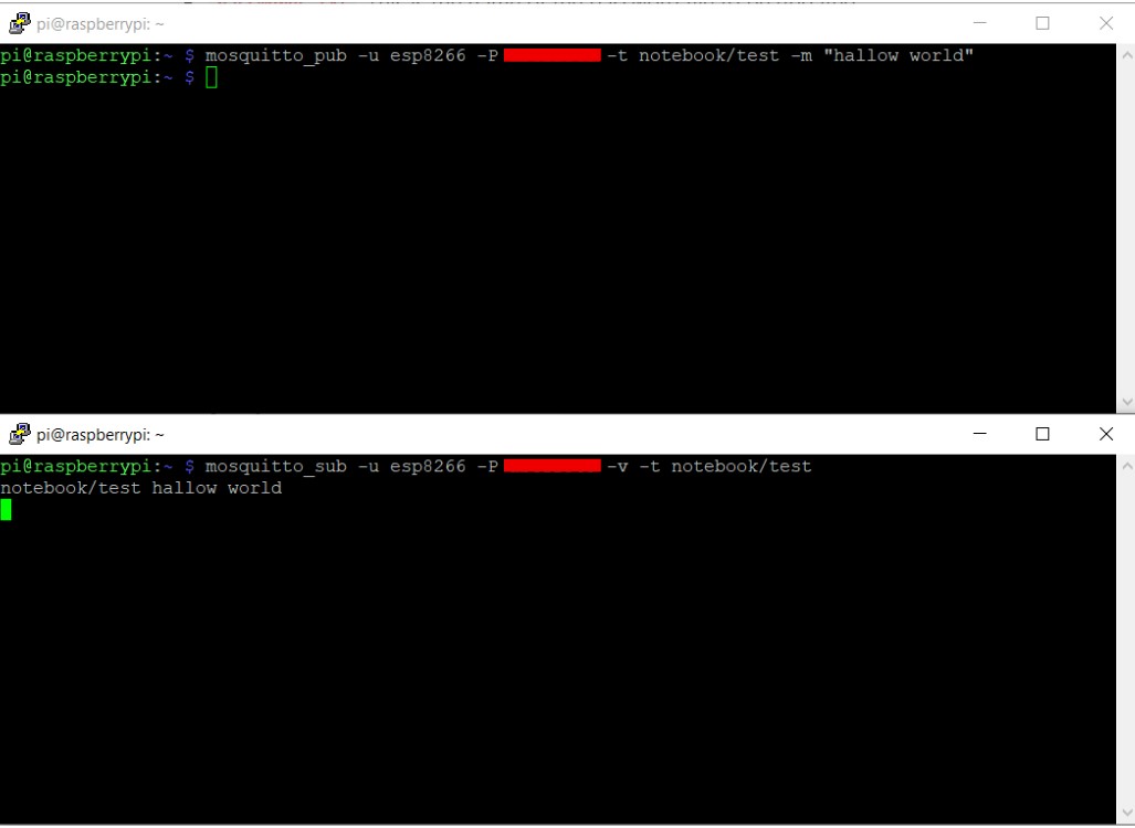
we have successfully configured MQTT with authentication .
MQTT on Node RED
If you search the flows you can find mqtt nodes .
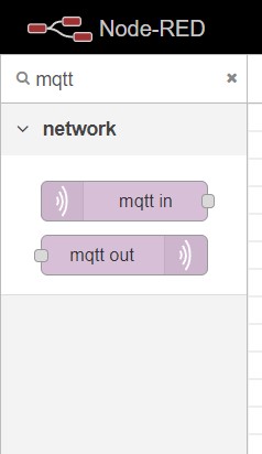
Input Node
Drag and drop an input node and a debug node , double click on the input node to show settings .
Click on the pencil icon to edit the node
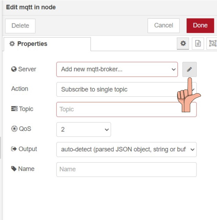
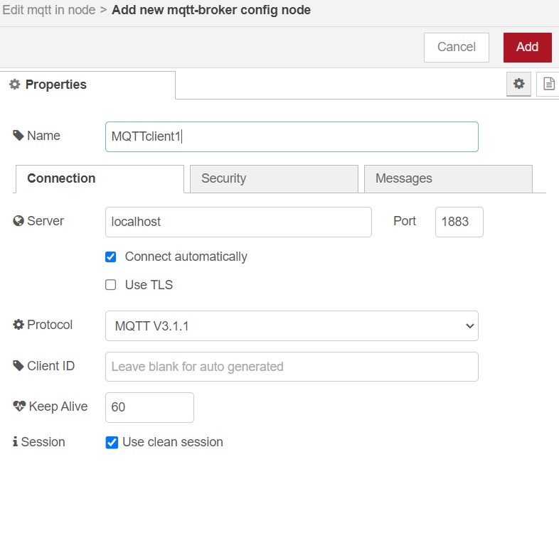
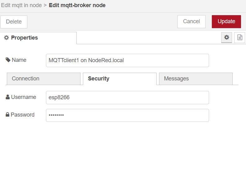
Add name for the node “MQTTclient1” and on Server
write localhost
On Security add the user name and password for nodered
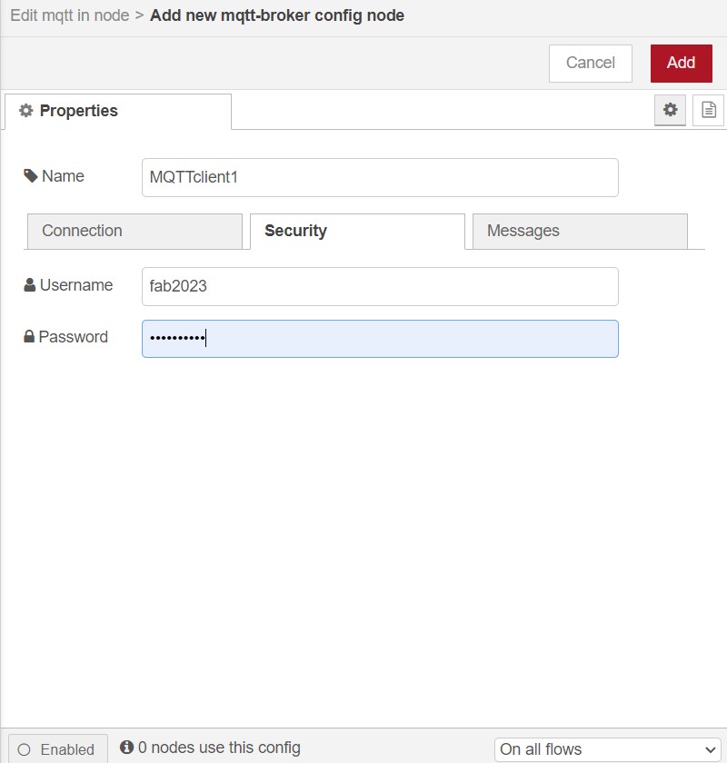
Click on Add
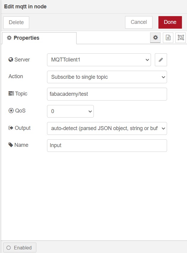
Give Topic as fabacademy/test and change Qos to
0
Now click on the Debug messages on the right side of the
tool bar .
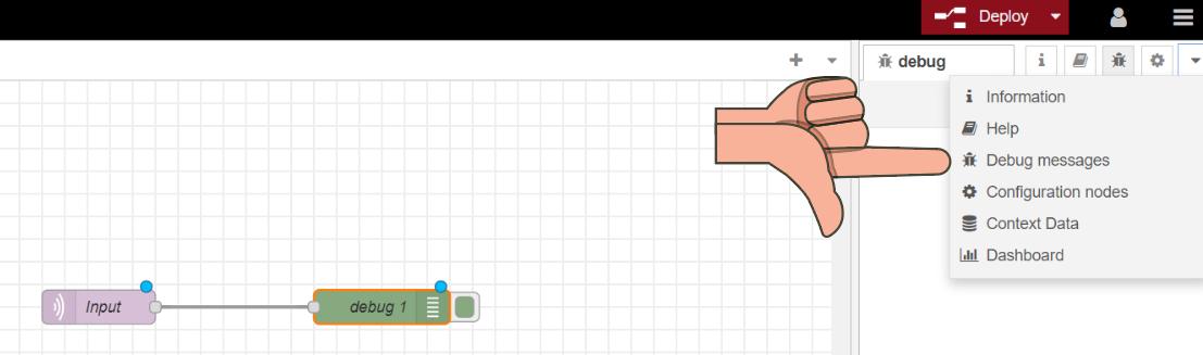
What is a debug node ? The debug node in Node-RED is
a tool that allows you to view and inspect the data that is flowing
through your Node-RED flows. just like a
Serial monitor on arduino IDE.
Now click on Deploy .
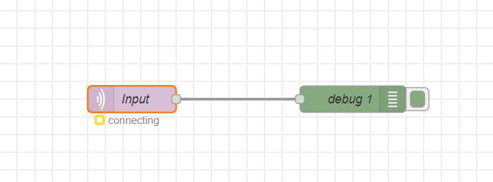
The input MQTT node failed to establish a connection. Although the
connecting status is displayed, the connection itself
does not appear to be established.
Fond the issue ( My mistake)
In the subsequent step, I mistakenly provided authorization for the Node-RED username and password instead of the credentials generated for MQTT.
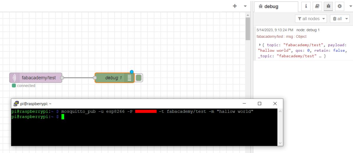
After deploying you can see the status of the node as
connected
which means the node is connected and working .
Inputting to the Subscribed Node
Publishing was done on the terminal and we have the message delivered at the debug window from the subscribed node .
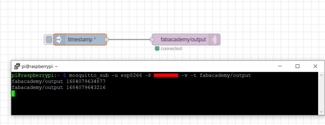
Output Node
In a similar manner, I utilized both the timestamp node and MQTT output node to transmit a timestamp message to the Putty terminal.
ESP32 input from Node-RED
Follow the library documentation .
https://github.com/plapointe6/EspMQTTClient
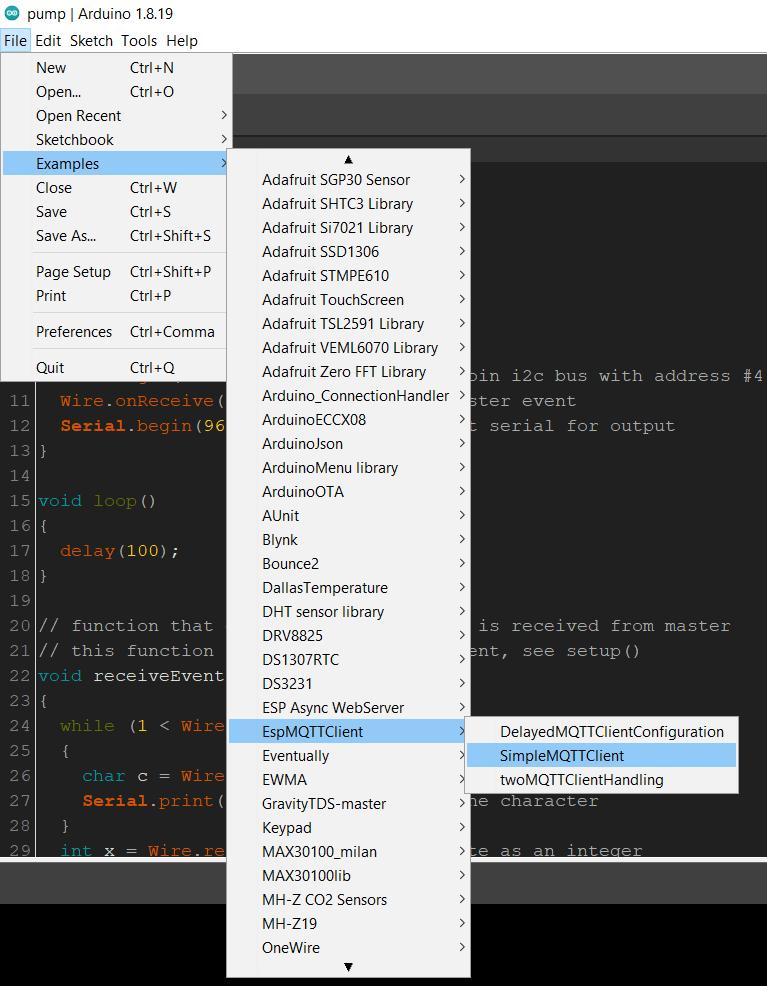
After opening the example simpleMQTTClient i changed the
wifi SSID , wifi PASSWORD , MQTT username , MQTT password , IP
                    address
. then uploaded the same code to ESP32 board ( since our lab had only
1 esp8266 and it was already in use ).
On the node red side i used a subscribe ( mqtt out ) node to display the contents received from the esp32 board
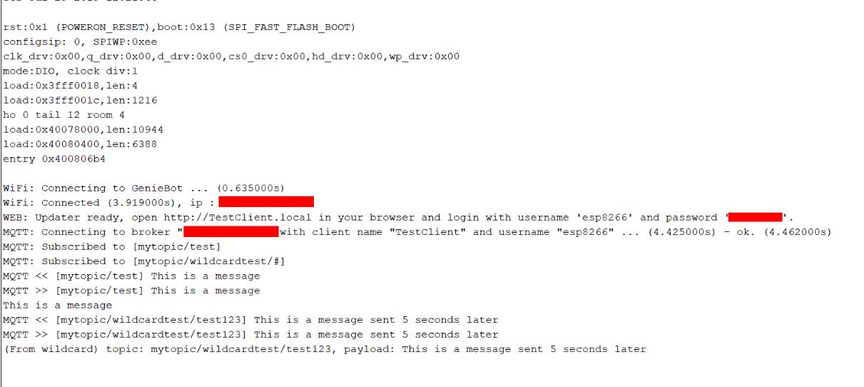
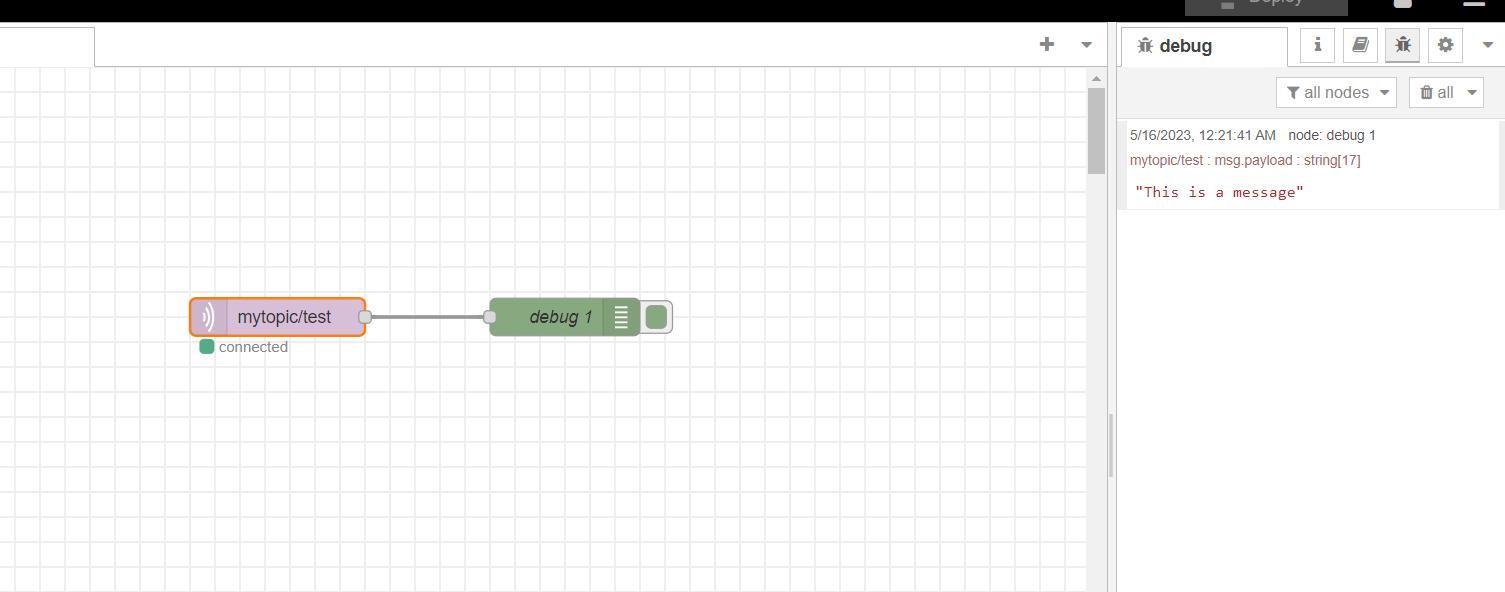
You can see the message from the esp32 board (This is a message) on the debug window
ESP32 Output to Dashboard
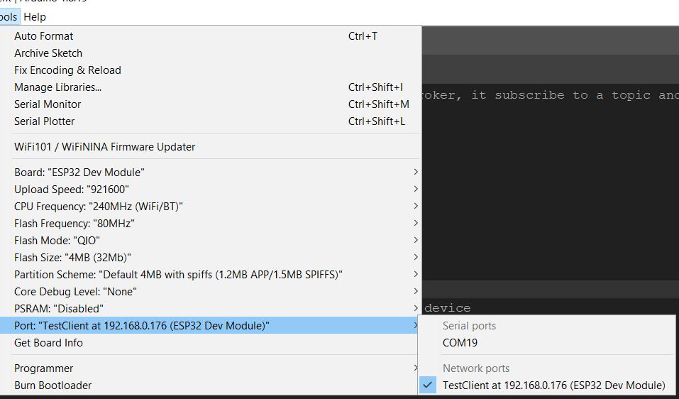
Uploading sketch to ESP32 Through OTA
You name to change both icon and colour
AS7341 (multispectral sensor)- ESP32 - Node-RED
The AS7341 sensor greatly interests me due to its capability for color analysis, making it an ideal fit for my primary objective of creating a personalized automated colorimeter for my hydroponics project.
pH colorimeters typically utilize colorimetric methods to assess the pH of a solution. These methods involve the use of indicators or reagents that change color in response to different pH levels. The color change is then quantitatively measured by the instrument, allowing for pH determination.
By utilizing this sensor, I envision accurate and precise measurements and analysis of the colors and pH levels of water within the hydroponic system. I hope this technology has the potential to eliminate the need for expensive probes traditionally used for such measurements.
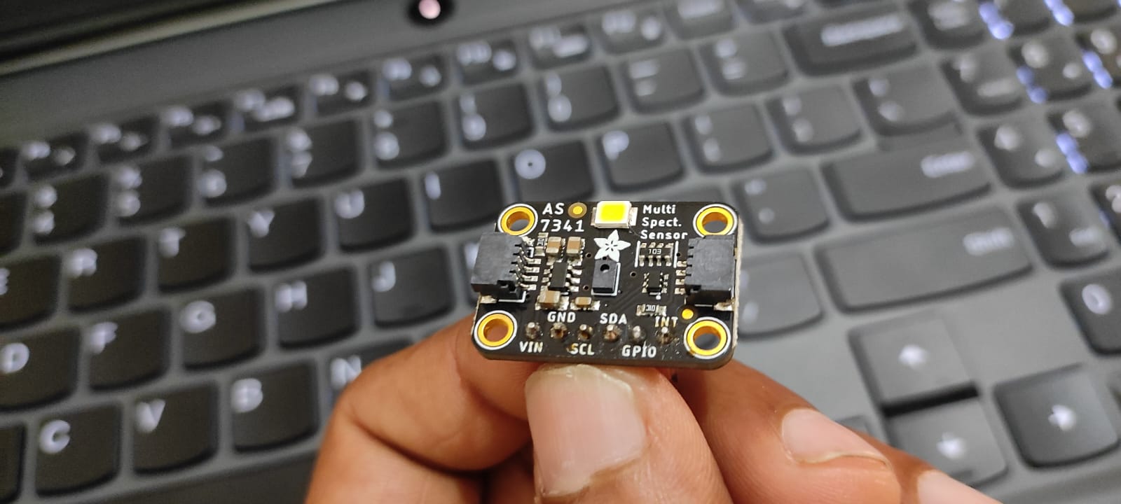
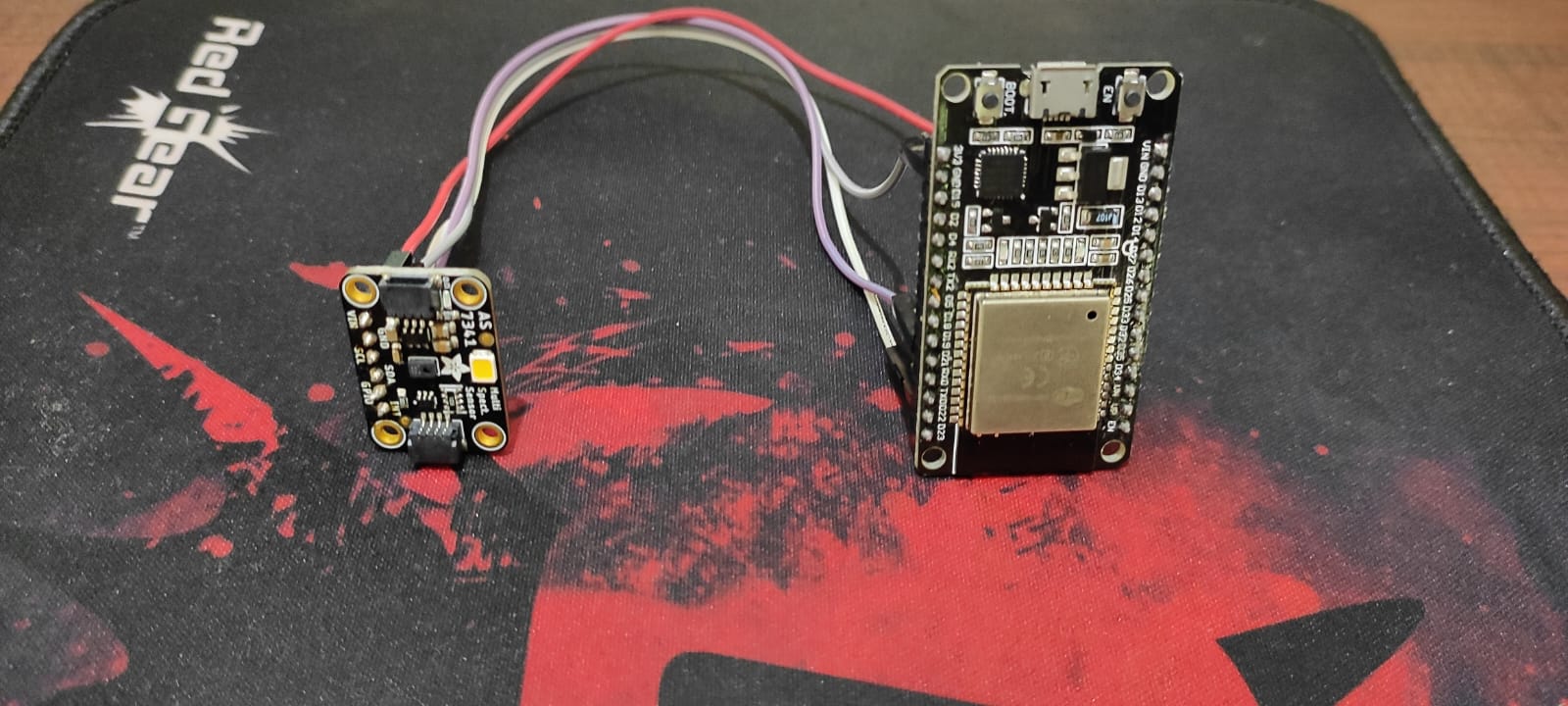
The sensor I had was an adafruit one .
 https://www.adafruit.com/product/4698

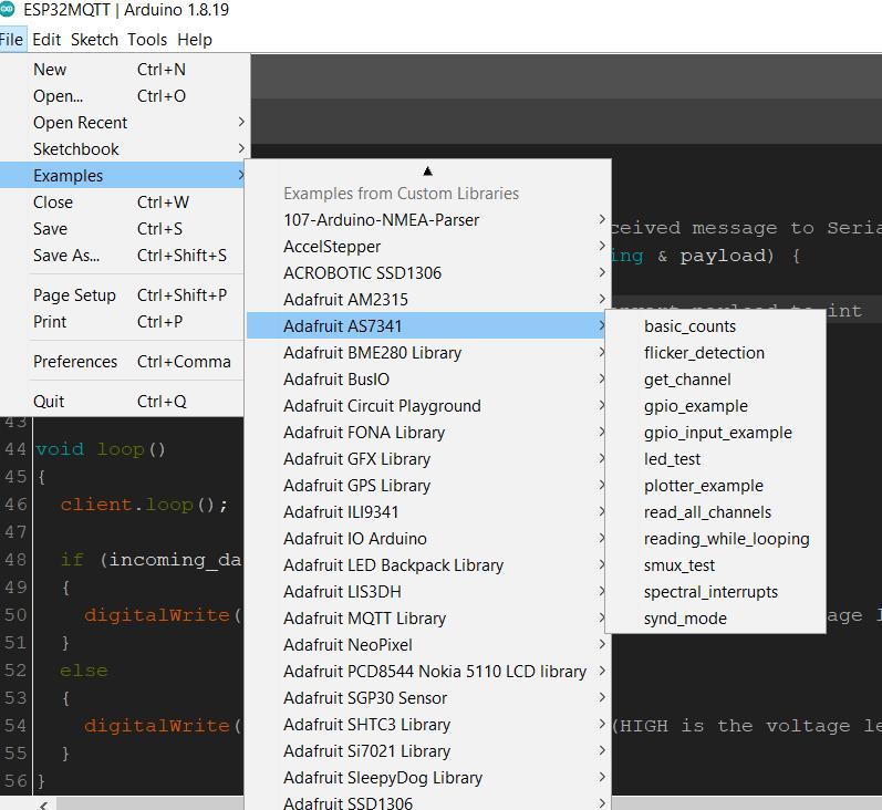
After installing libraries I found the example library ” basic count”
The serial monitor displayed float values from the uploaded code i was expecting values in nanometer .
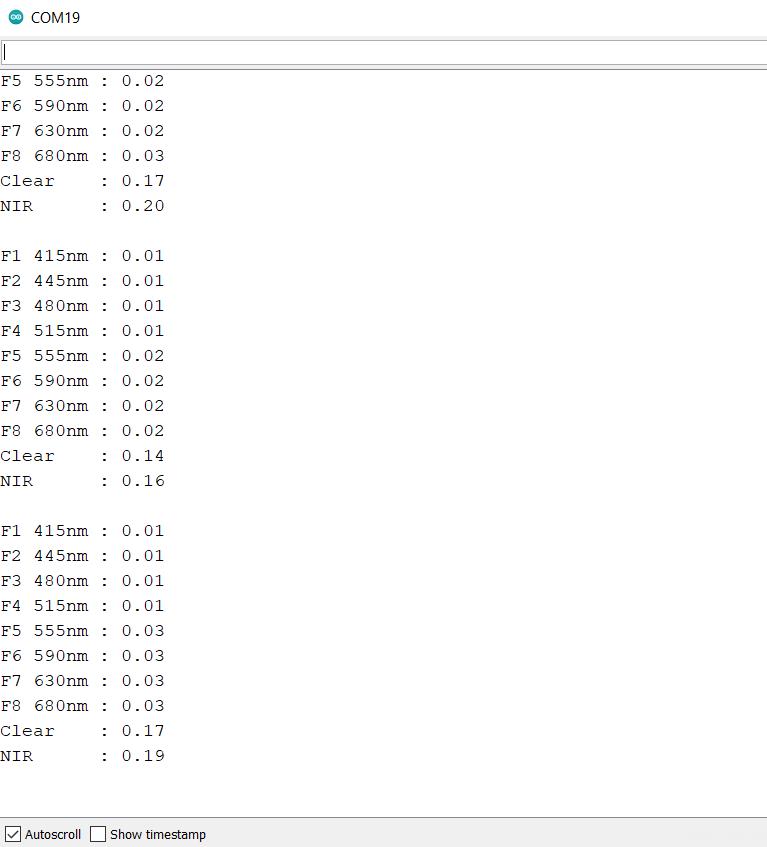
I went through another example from adafruit which had outputs in nanometer range .
following is the example .
 https://learn.adafruit.com/adafruit-as7341-10-channel-light-color-sensor-breakout/arduino

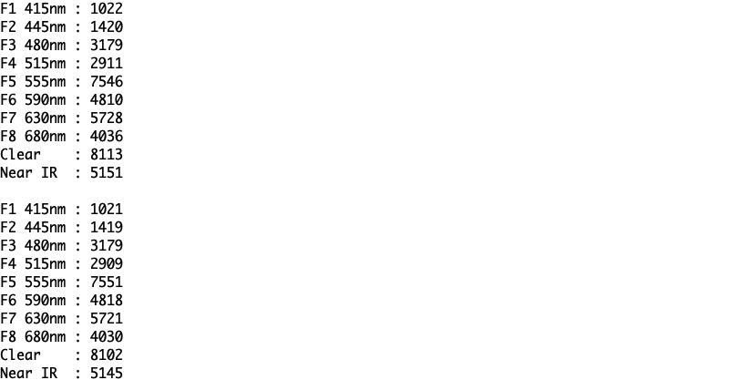
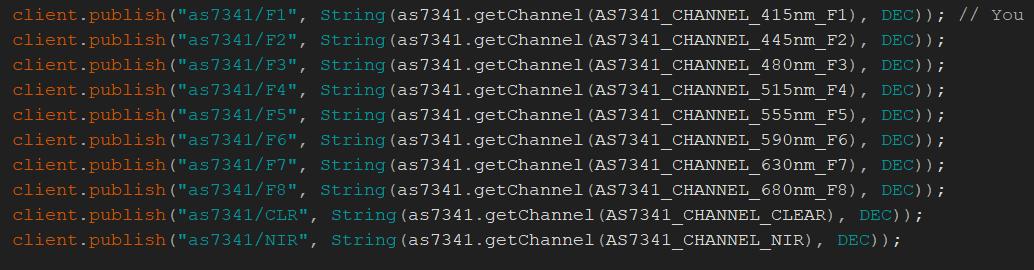
I utilize client publish commands to send all the codes to Node-RED for output.
Back to Node Red
I wanted to output all the Spectrums on an interface so I added gauges (from the dashboard ui ) and added subscriber to it . now its time to edit the dashboard .
Click on the dashboard
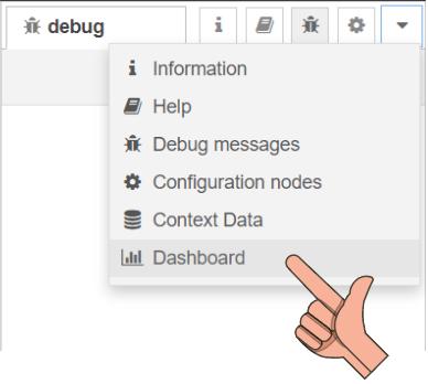
Then click on the layout
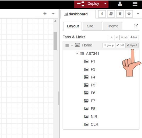
In Node-RED, I arrange the gauges on the panel through a simple drag-and-drop process. This awesome Node-Red feature that allows me to easily position and organize the gauges according to my desired layout and visual presentation.
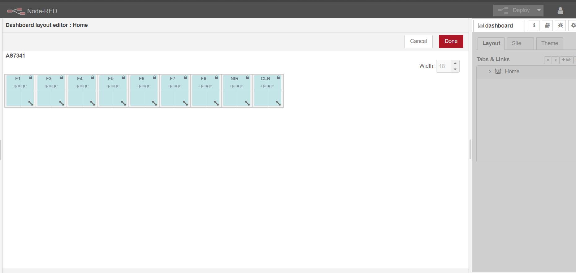
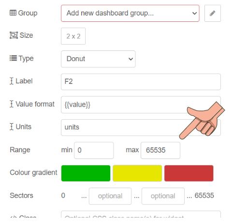
Editing The gauge Node
The AS7341_CHANNEL_415nm_F1 channel is a 16-bit value, which means its maximum value is 65535.
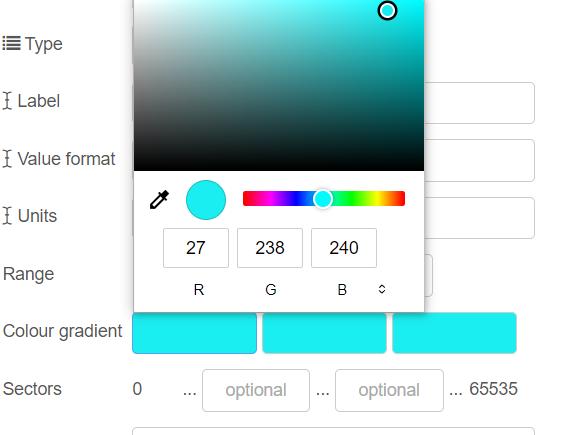
Thanks to ChatGPT, I discovered the corresponding color of a specific nanometer range.
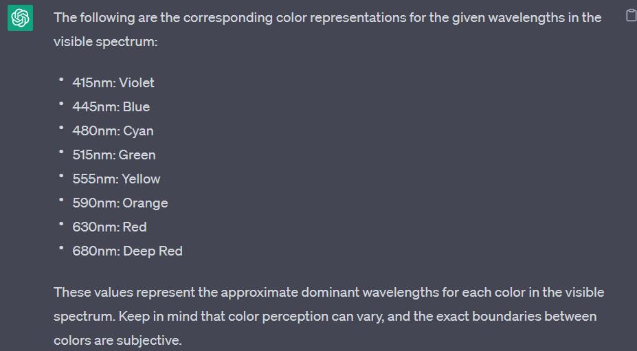
I carefully selected the appropriate color for each gauge based on the corresponding nanometer range. By matching the specific wavelength range to its corresponding color, I ensured that each gauge accurately represents the desired color for the given nanometer range.
Discovering Colors in Real Time 🔥 😎
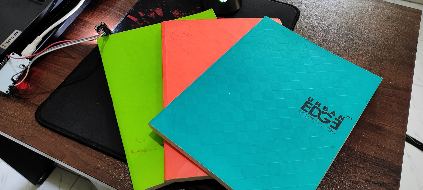
Inspired by the vibrant and deep colors on some of my book covers, I decided to utilize them as a reference for color detection. 😄.
Finally sensing Colors and displaying them on Node-Red via MQTT
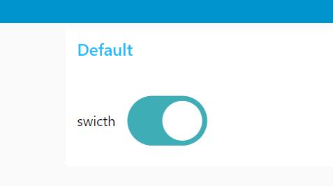
A small Node-Red to ESP32 example
Using the Switch UI on the dashboard, I toggled the onboard light of the ESP32 on and off.
Finally I think I learned a bit about Output and input on node red via mqtt .
Still the assignment is not complete until i do the same from My own board . Unfortunately I did not have any board with esp32 or WIFI modules on my previous assignments .
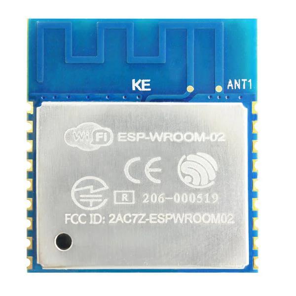
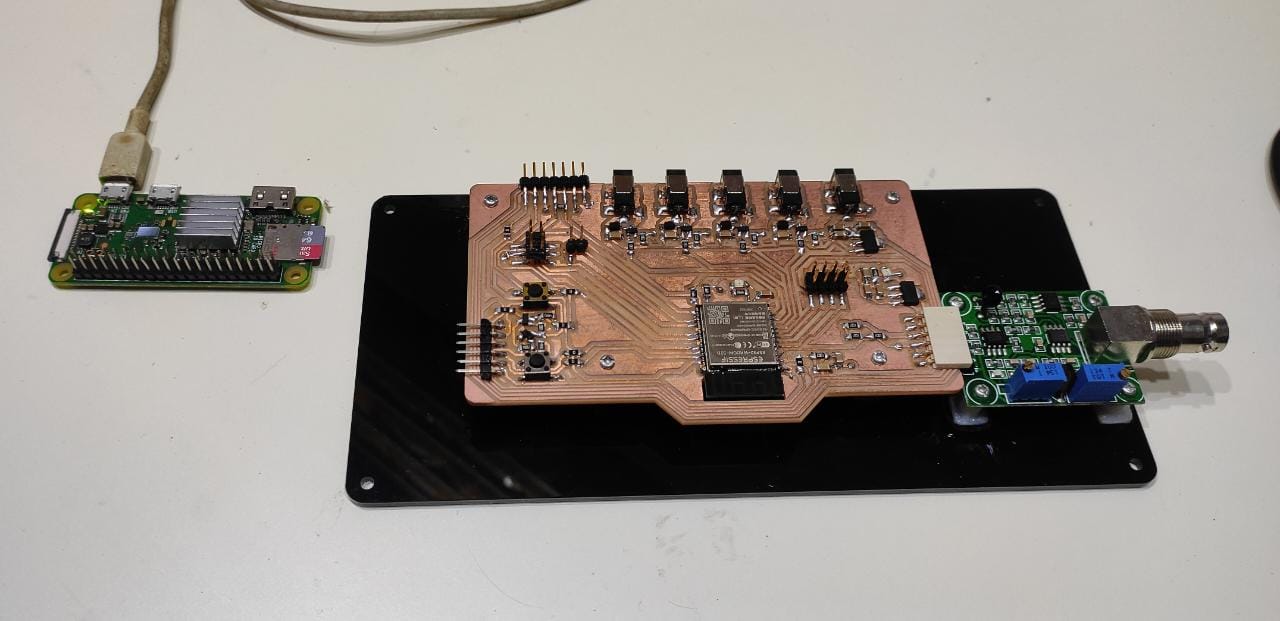
Making a circuit and PCB for my own esp8266 (Wroom 02 ) AS7341 sensor
Considering that the AS7341 sensor did not require the extensive capabilities of the ESP32, I opted to create a dedicated board for this task using the ESP8266 WROOM. The ESP8266 provided ample functionality for running the AS7341 sensor, making it a suitable and efficient choice for the assignment.
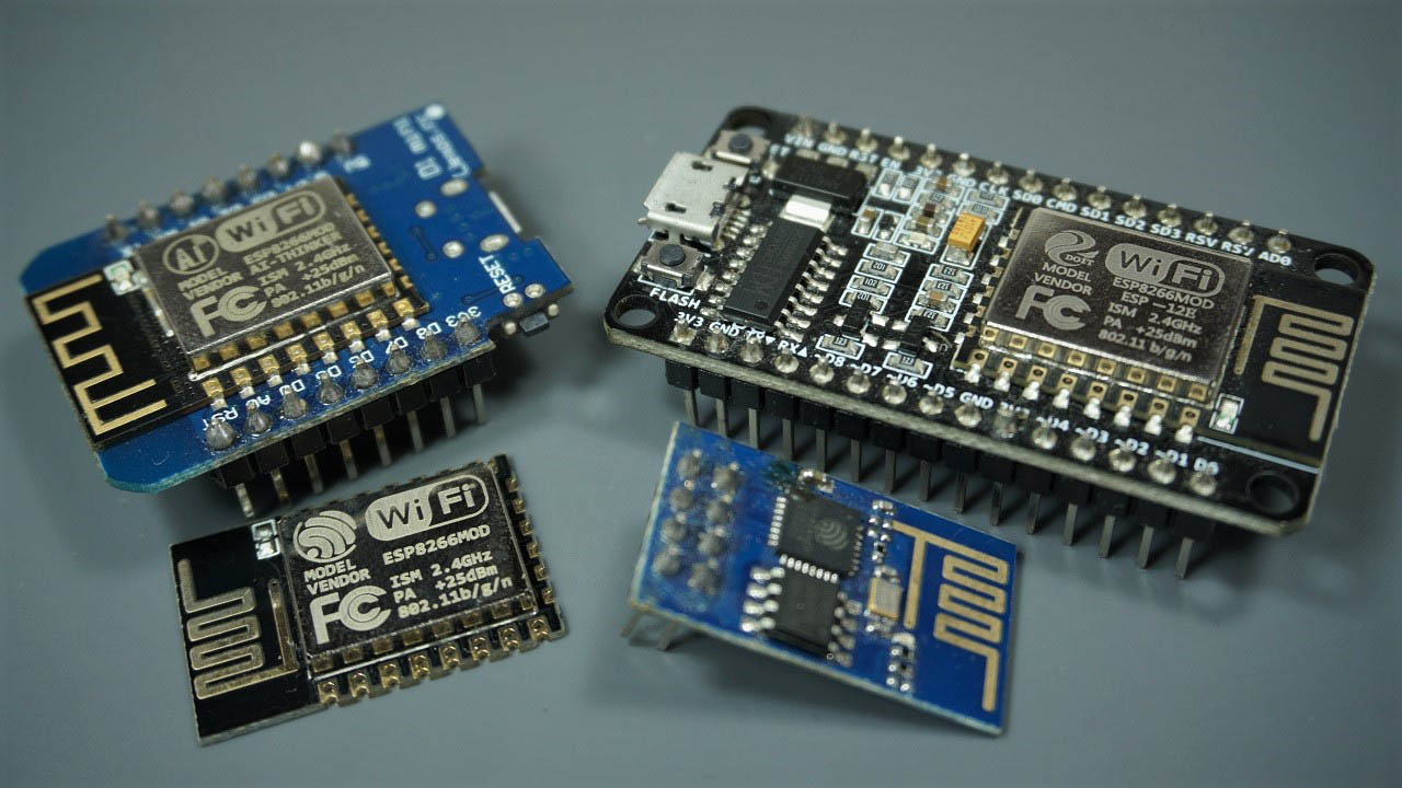
Random nerds had the best documentation on esp8266 following is the link .
 https://randomnerdtutorials.com/esp8266-pinout-reference-gpios/
Auto program and reset 😕
In the context of the ESP8266, "auto program and reset" refers to a functionality that allows for automatic programming and resetting of the board. This feature simplifies the process of uploading new firmware or code onto the ESP8266 without the need for manual intervention which is done through switch .I wanted to implement the same feature on my board This feature is particularly convenient during development and testing phases, as it eliminates the need to manually press buttons or perform specific actions to initiate programming or reset operations on the ESP8266 board.
Following is a link in to how the auto program works on esp8266

I went through the Adfruit Huzzah board which had esp8266 ( click here for schematic ).
They have places 2 mmbt2222 transistor for auto program .
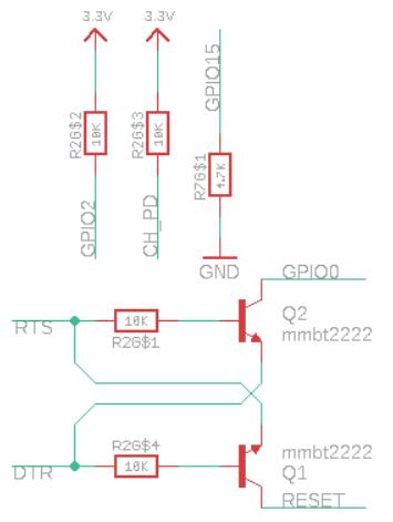
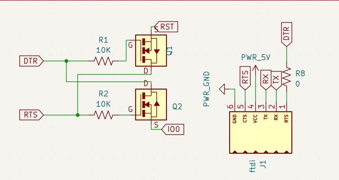
Due to a lack of surface-mount device (SMD) transistors in our inventory, I needed to adapt the circuit by replacing the transistor with a MOSFET.
During discussions with my instructor, Saheen, I learned that he had previously employed a similar circuit using a MOSFET for an ESP32. Consequently,
I decided to implement the same approach in my circuit.
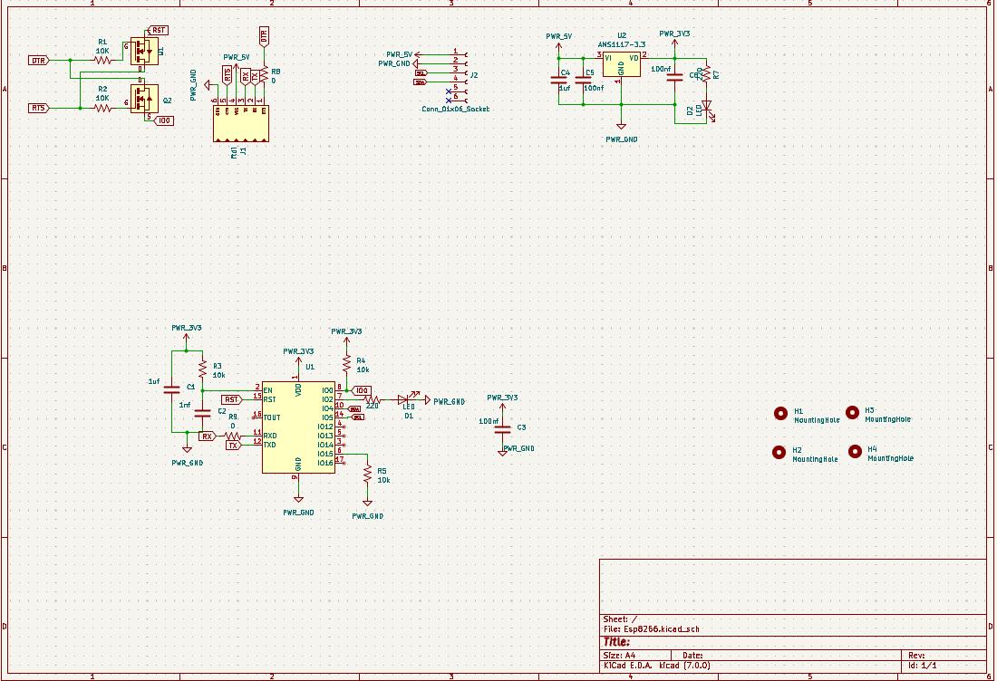
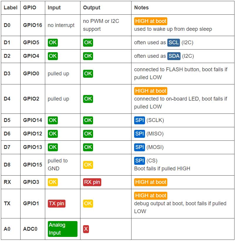
Rest of the circuit were of not much effort AS7341 is using i2c and I additionally added an led on gpio 2.
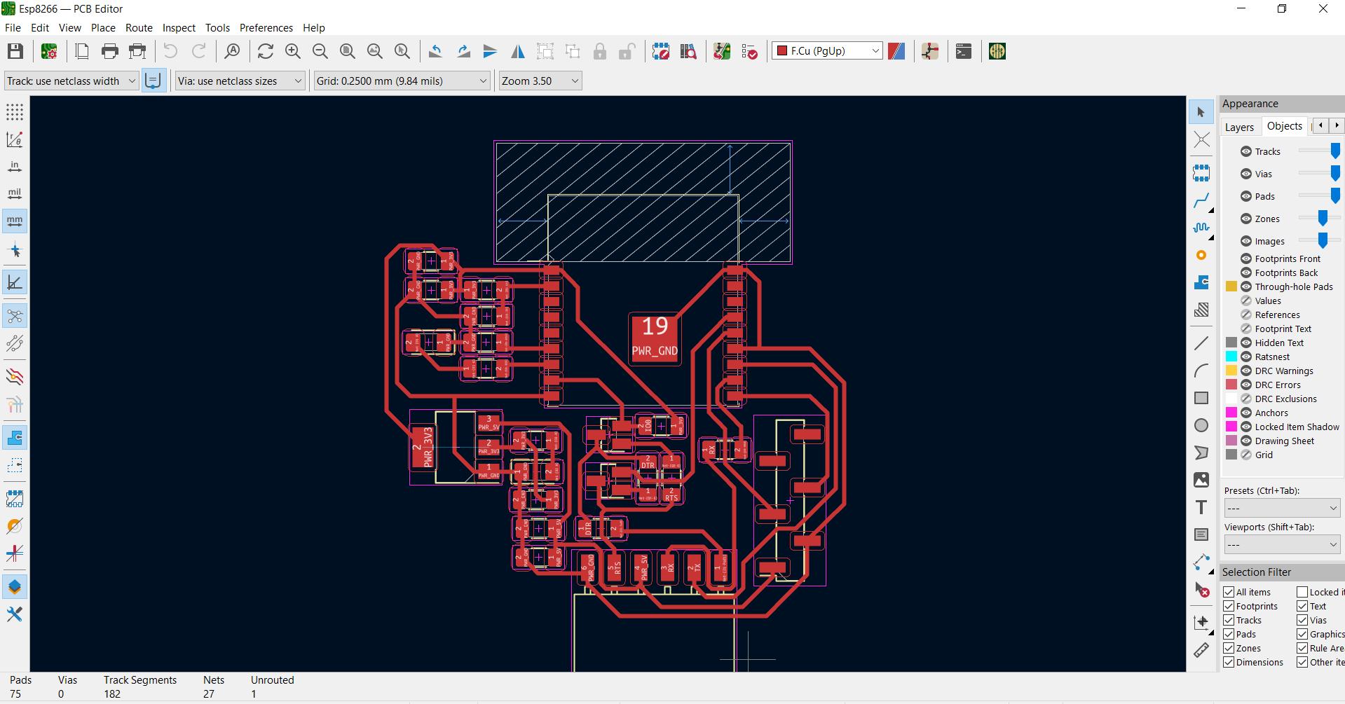
ON to PCB design
During my exploration, I discovered that the ESP8266 module has specific design restrictions for its footprint, particularly regarding the placement of traces or PCB in certain areas after digging through data sheet i found that It is generally recommended to avoid placing a printed circuit board (PCB) or any conductive material in close proximity to the antenna of an ESP8266 module. This is because the presence of conductive materials near the antenna can negatively impact the performance and efficiency of the wireless communication.
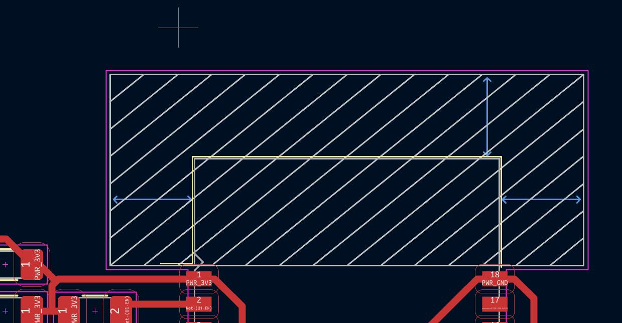
My initial attempt at design .
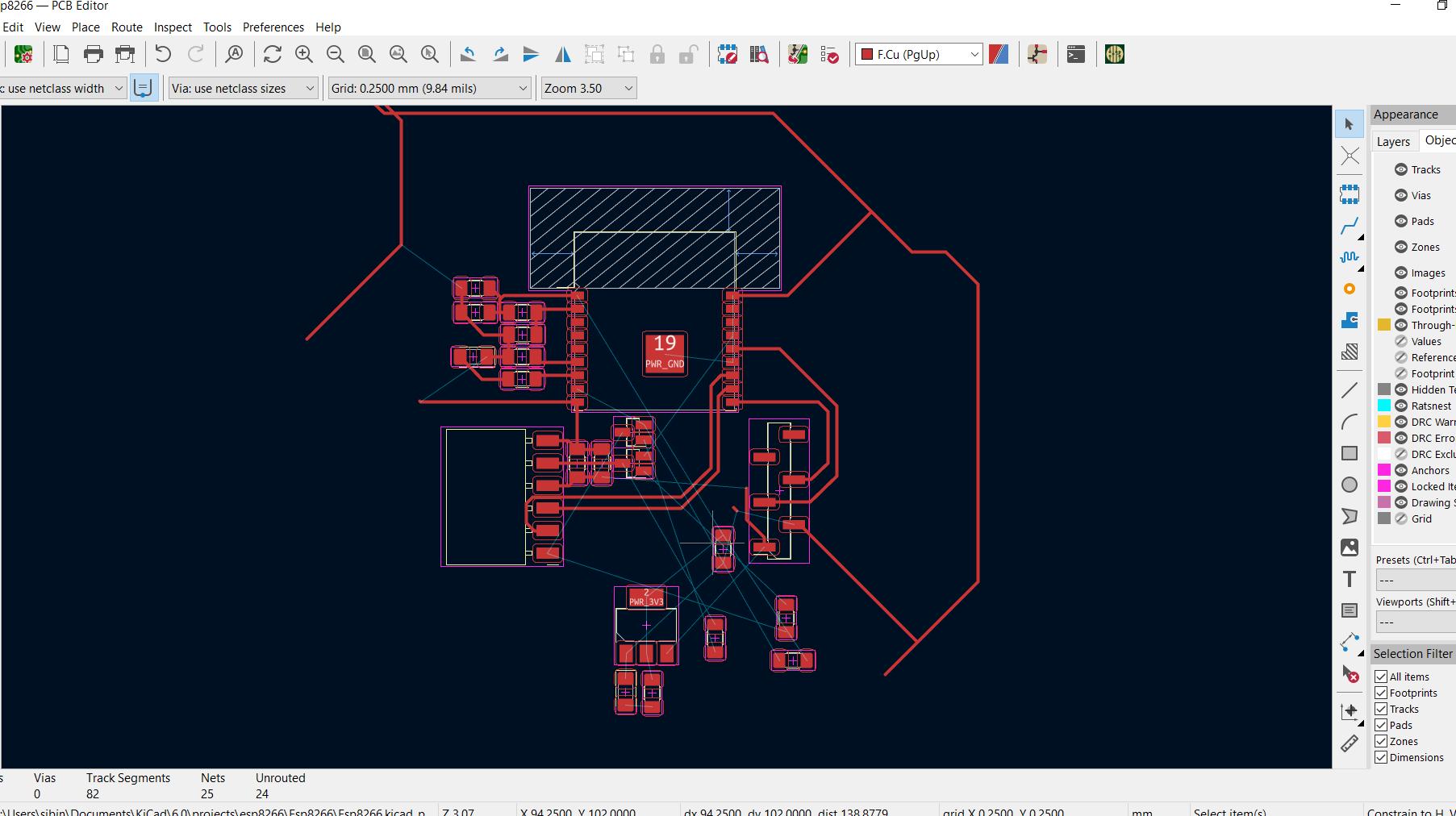
My final design .
And….. I exhausted my week 😭😭😭😭
Due to time constraints, I was unable to complete the milling or fabrication of my ESP8266 PCB before reaching my deadline for the week. However, I plan to revisit the project after my presentation to finalize the PCB. Additionally, I am considering implementing my project with an ESP32. I aim to return this week and provide the necessary documentation for integrating ESP32 and Node-RED into my project.
ESP32 - Node red implementation on my PROJECT ( Week 14 revisited )
Documentation on The Schematic , PCB and Fabrication is updated on my project page
Please find the documentation on the following link -
By utilizing the same codes and flows, I established a connection between the pH sensors and Node-RED through an ESP32. Subsequently, I placed the pH sensor into a beaker containing a pH7 buffer solution.
Readings shown on Node-Red guage
Conclusion
I realized that the values were constantly fluctuating, indicating the need for additional implementation of smoothing algorithms to stabilize the pH readings. My understanding is that what I accomplished on Node-RED is merely scratching the surface, and there is a great deal more to explore and experiment with as I continue working on my project.
Resources and Downloads 📩
📩 Arduino sketches ESP32-Light Spectrum and Simple MQTT📩 ESP8266 PCB and schematic
📩 Node-Red flows export file