WEEK 07 - Computer controlled machining
👉 Individual assignment:
- To create a large-scale object, such as one that measures meters, the process typically involves designing, milling, and assembling various components.
👉 Group assignment:
- lab's safety training
-
Table of content
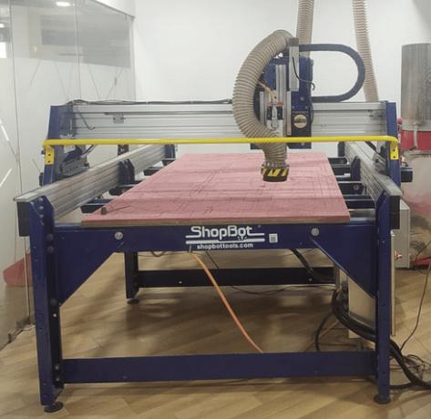
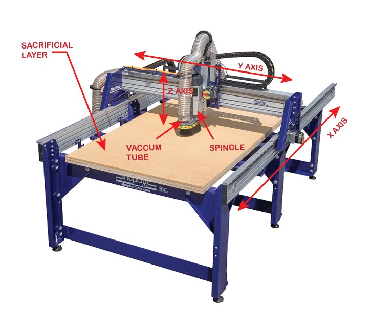
ShopBot
Super fablab kochi owns a 3 axis wood CNC from ShopBotTools shopbot.com . It has a moving area of around 2.67m x 1.55m x .2m . Unlike the Zund G3 L machine, the ShopBot lacks any sort of automated awareness system. As a result, it's crucial for us to exercise extra caution and vigilance when operating the ShopBot.
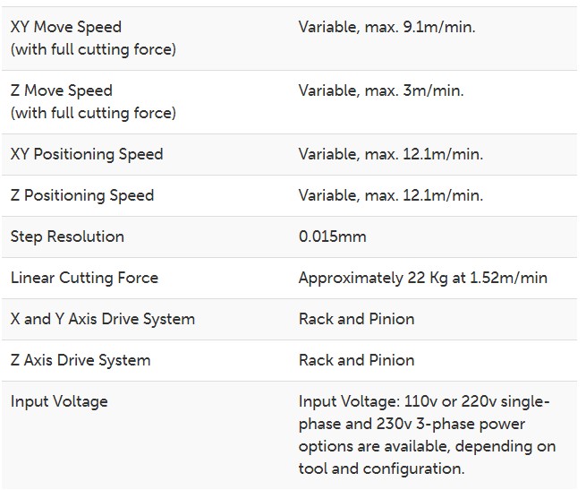
Specifications
Group Assignment
Jojin, our instructor, provided us with comprehensive safety training on how to operate the ShopBOT CNC router. During the training, we learned about the potential hazards and the necessary precautions to take while using the equipment. This instruction was crucial in ensuring that we were equipped with the knowledge and skills required to operate the router safely and efficiently.
Our team conducted experiments to assess the design parameters of our ShopBOT CNC router. Click the link below to view our collaboration!
Inspiration
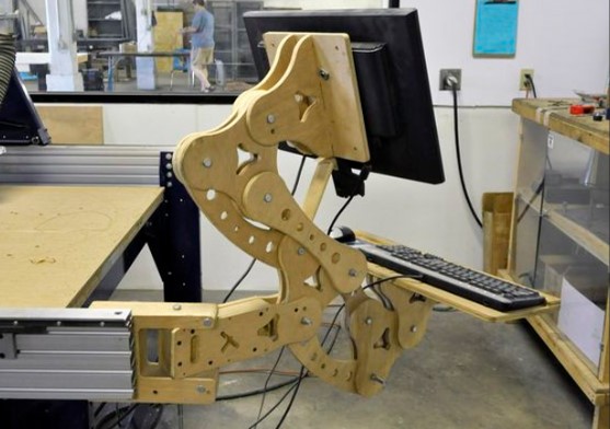
I've been racking my brain for some time now trying to come up with a design that really pops. After scouring through a plethora of designs on some of the furniture websites like ifurniture , atfab ,chairgami and Pinterest .
Finally something caught my eye I found a design that perfectly blends form and function.
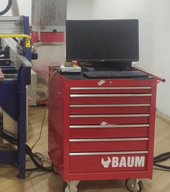
Our ShopBot machine was in dire need of a proper workstation for the PC.
I embarked on a mission to fabricate a workstation that boasts the ultimate flexibility – equipped with the ability to rotate and tilt to one's heart's desire 😎
Design
Why not try Inventor ?
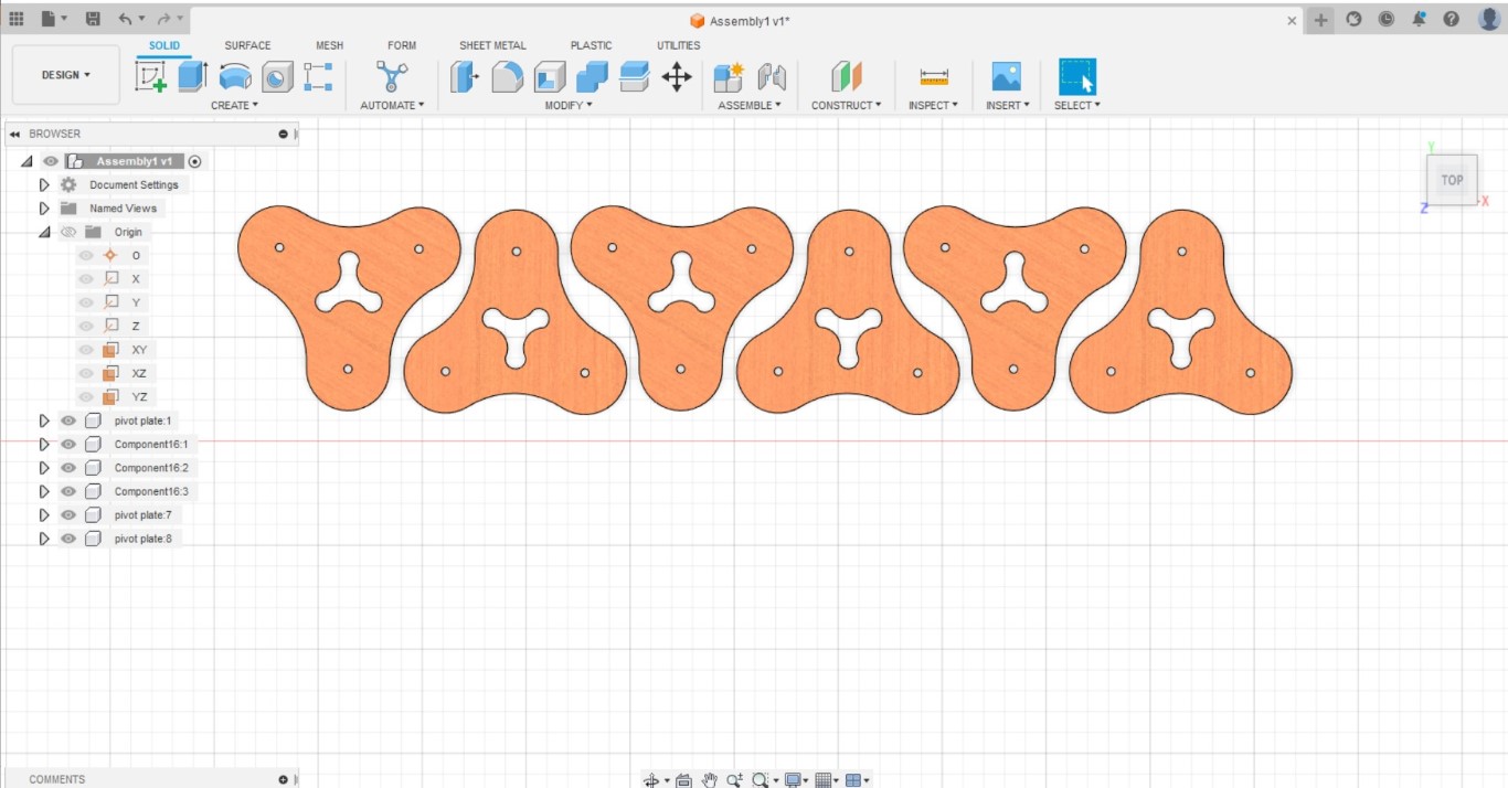
So i started the design on autodesk inventor first i created a pivotal plate, which serves as the fundamental building block of the entire design .
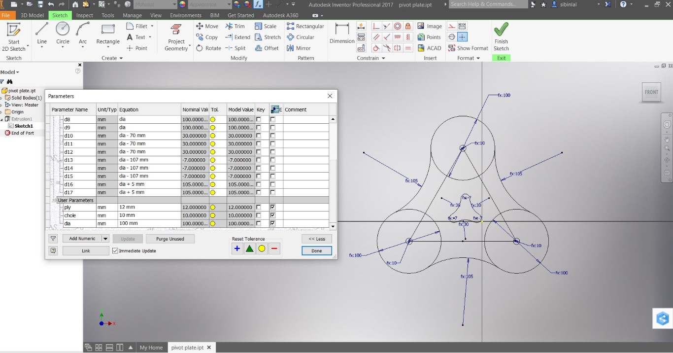
To open the parametrics on inventor click on the top
Fx function
. After predefining most dimensions such as plywood size ( most
importantly ) on parametrics . I drew out the design for
the pivot plate .
Tools used ( spline , circle , and line) .
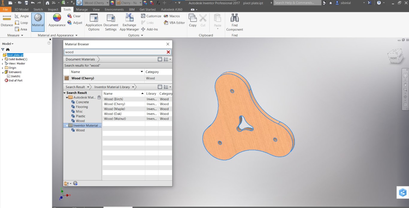
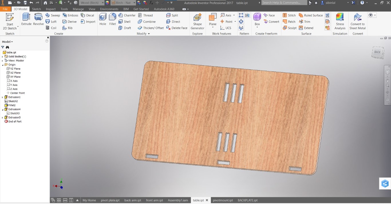
After extruding the design to the ply thickness , I changed the
material composition
from Tools > Materials ( search wood ) to wood . So
that i would look more realistic .
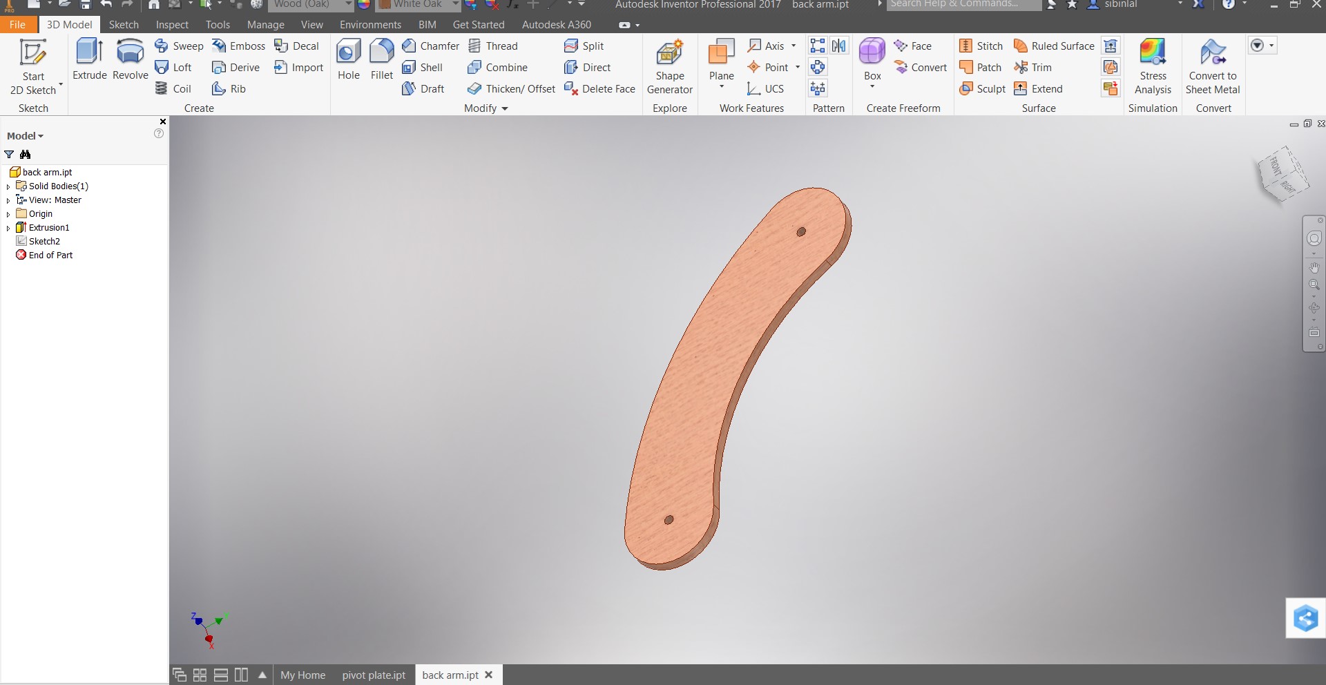
Then on to the next design which I call the “Back arm” which supports pivot plates from the back side .
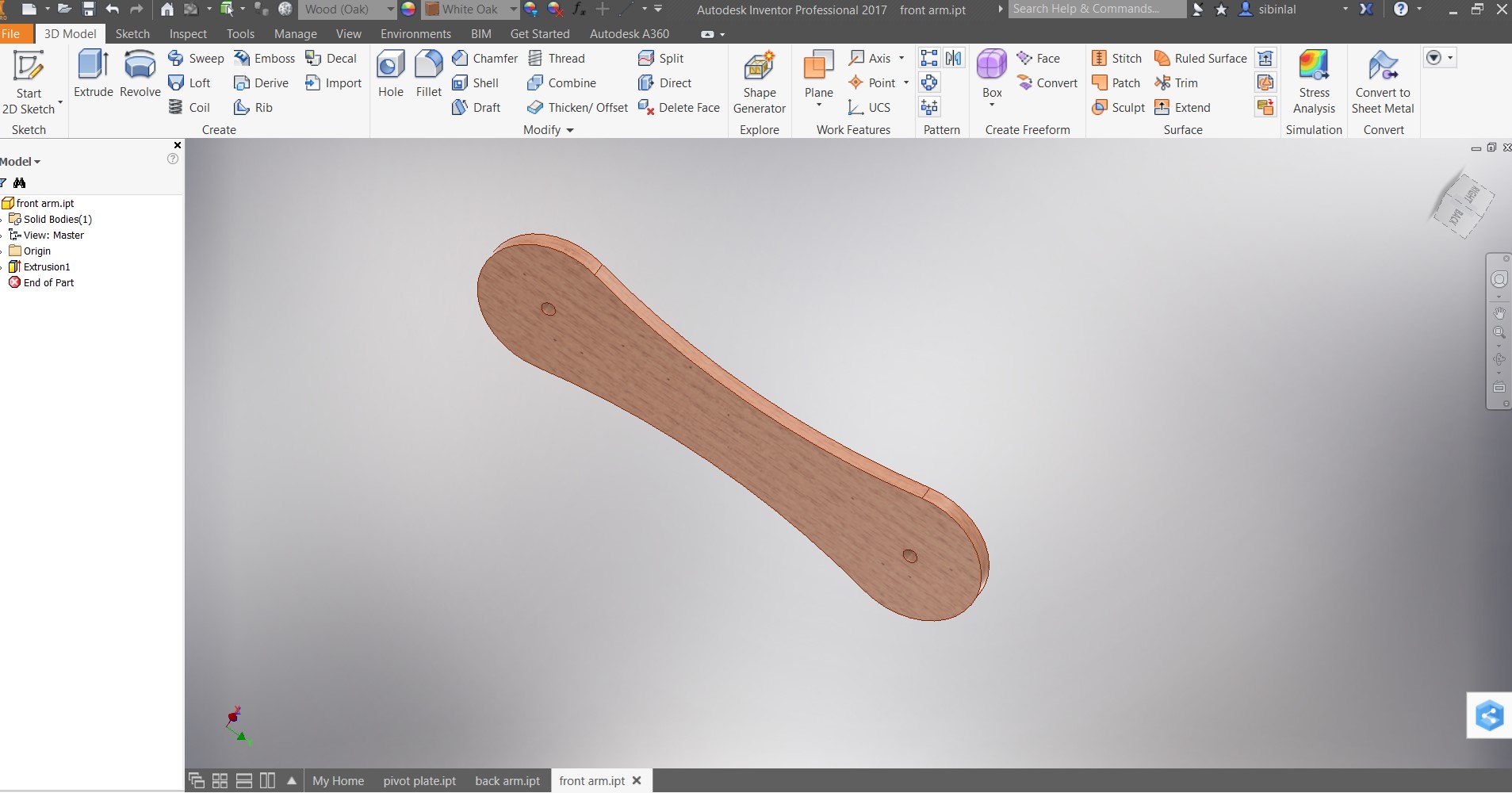
The anterior arm, responsible for providing front-side support.
I modified the pivot plate to make a pivot mount on to which i can join keyboard table / monitor wall mount back plate .
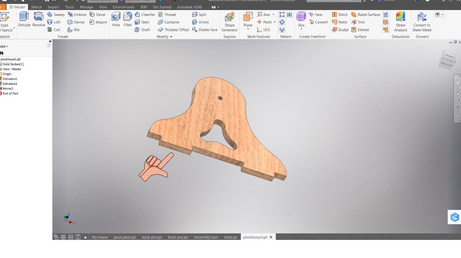
To simplify the process of joining the piece to the neighboring fixture, I incorporated a tenon joint.
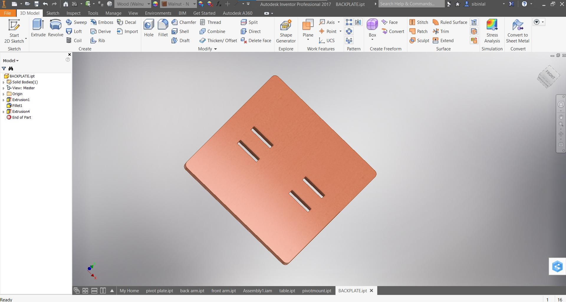
Mount plate for the PC monitor 👆🏼. The tenon joint from the pivot mount joins the back plate through the provided mortice holes .
At long last, after incorporating a designated table for the keyboard and mouse, the design reached its completion. Now its time for assembly .
Design Assembly
In Inventor, an assembly file (.iam) is used to manage and combine multiple part files (.ipt) into a single model. The assembly file contains information about the location, orientation, and relationships between the parts in the assembly.
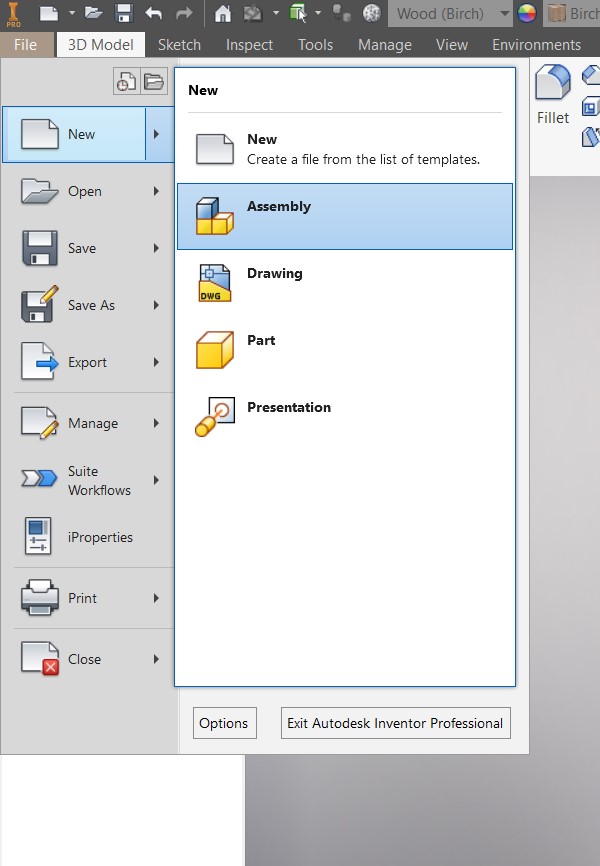
When creating an assembly in Inventor, you can add parts to the
assembly by placing them in the assembly file, or by using the "
assemble > Place Component" command to import
existing part files into the assembly. You can then use assembly
constraints to define how the parts fit together, such as by defining
mates, aligning parts, or specifying clearances.
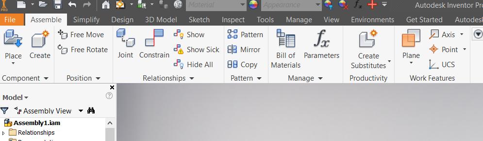
To assemble two elements in Inventor we use the
constrain command in assemble.
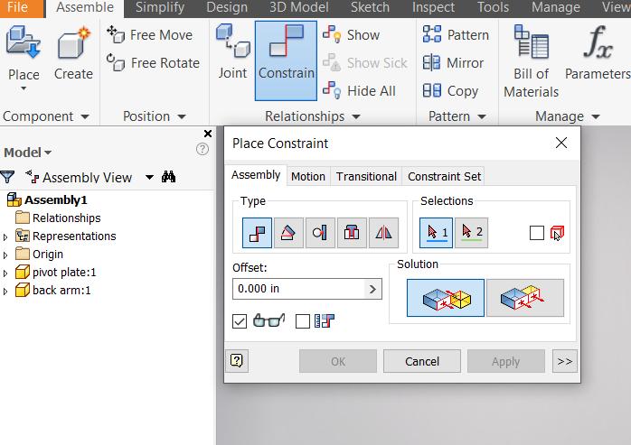
In Inventor, there are several types of constraints that can be used to constrain components in an assembly. Some common types of constraints include:
-
Mate constraint: This constraint aligns two components to a specific point, line, or plane.
-
Flush constraint: This constraint aligns two faces of components so that they are coplanar.
-
Angle constraint: This constraint controls the angle between two components.
-
Tangent constraint: This constraint ensures that a curved surface of one component is tangent to another surface.
-
Insert constraint: This constraint ensures that a component is inserted into another component at a specified distance.
Constraints can be added in several ways, including by using the "Constrain" command, by dragging and dropping components onto one another, or by using the "Mate" or "Align" commands. Constraints can also be edited or removed as needed.
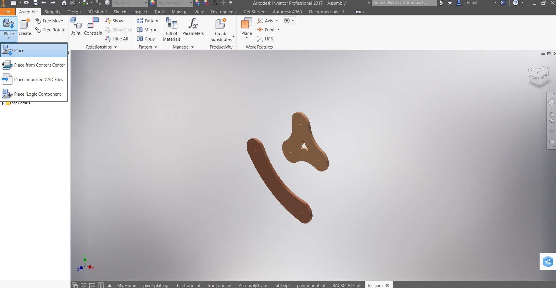
I placed two components that needs to be assembled .
Follow the video to learn how to constrain 2 different components .
I used both axis and mate constraint to form
the assembly .
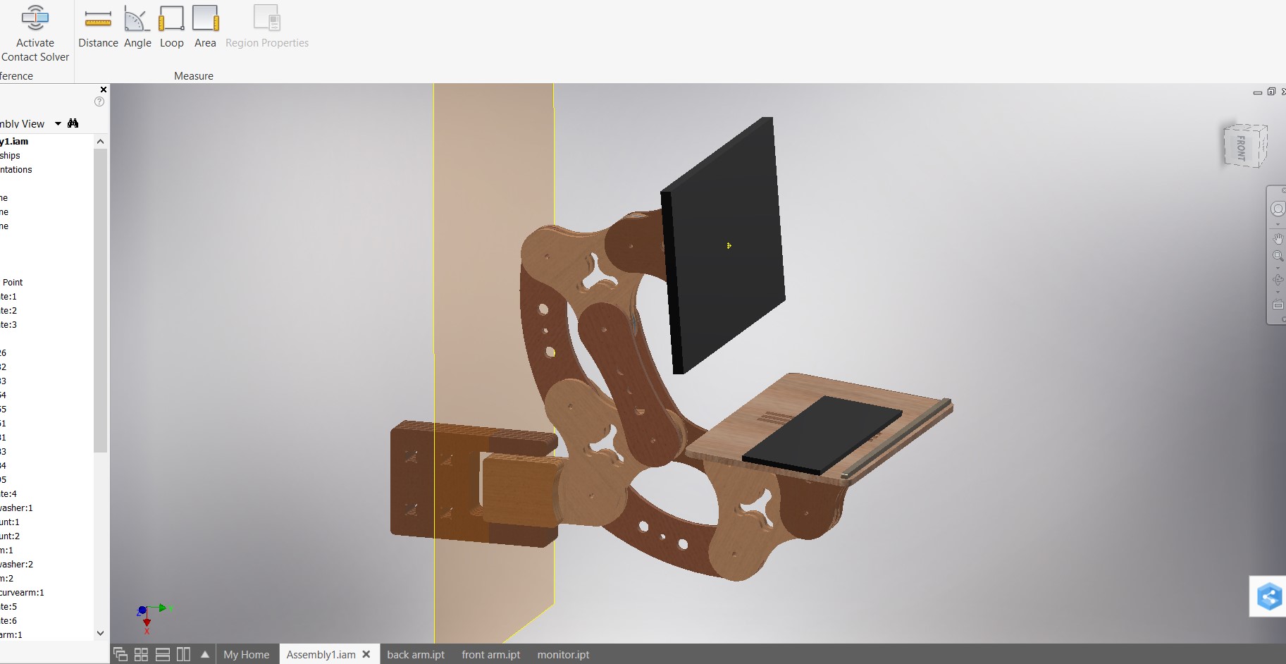
After placing all the components and applying the constraints to form all the axis of the assembly this is what it looked like.
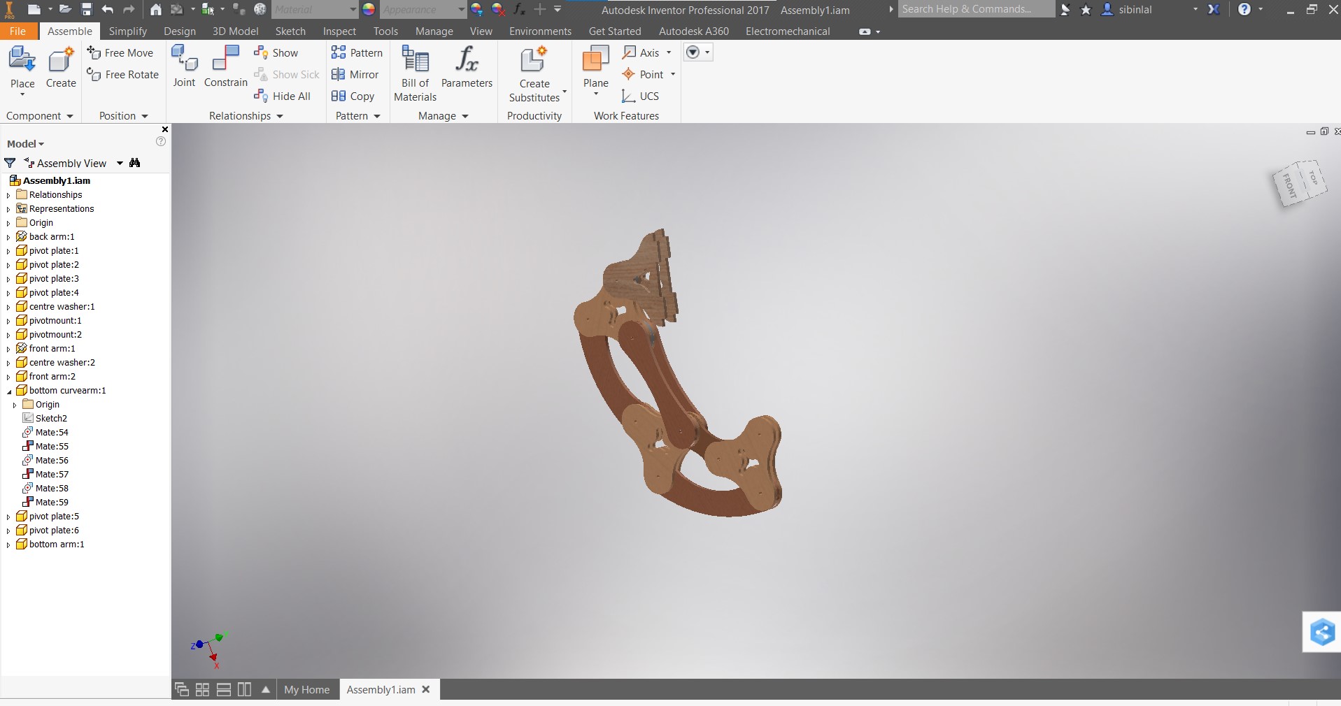
The motions of the assembly was not satisfactory so I started tweaking the design !
And finally some motion
Finally added the mount plate and Table for keyboard .
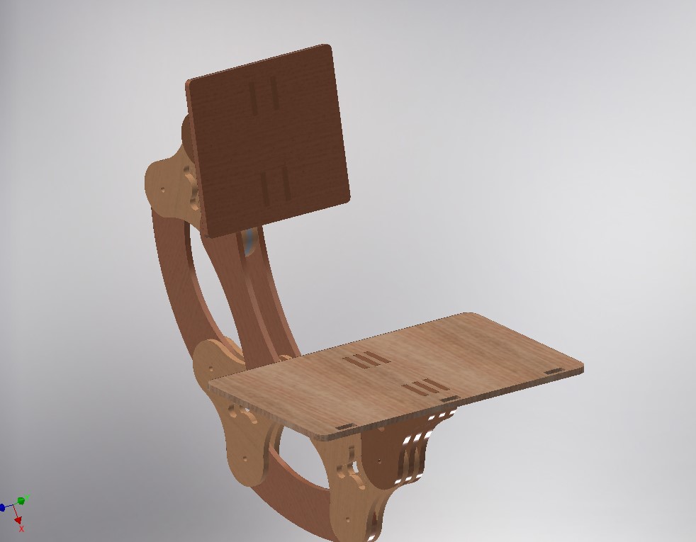
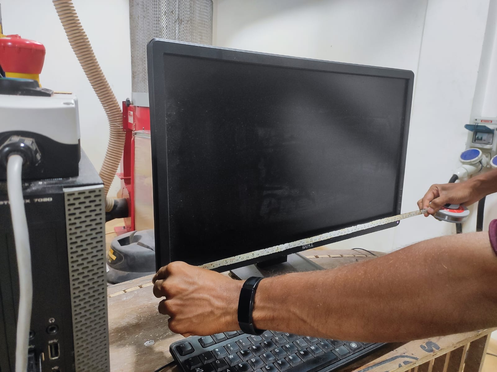
Thinking it would enhance the overall realism of the design, I decided to take measurements and create a design for the monitor and keyboard.
final design after cosmetic makeover
I had a desire to design a functional stand for my final hydroponics project, and I was optimistic about completing the model sometime this week since the time and machine availability was limited . I had to form a design ASAP .
Design 2
Ideation
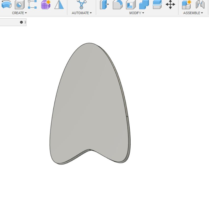
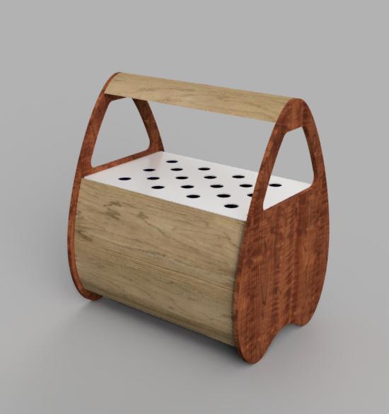
After going through various designs, I eventually settled on a tear drop shape which possesses an appealing aesthetic quality.
Initially, I began designing the vertical component of the stand, but it took some time to fine-tune and optimize the measurements of the design.
I utilized the same tools that I had previously employed to design the workstation.
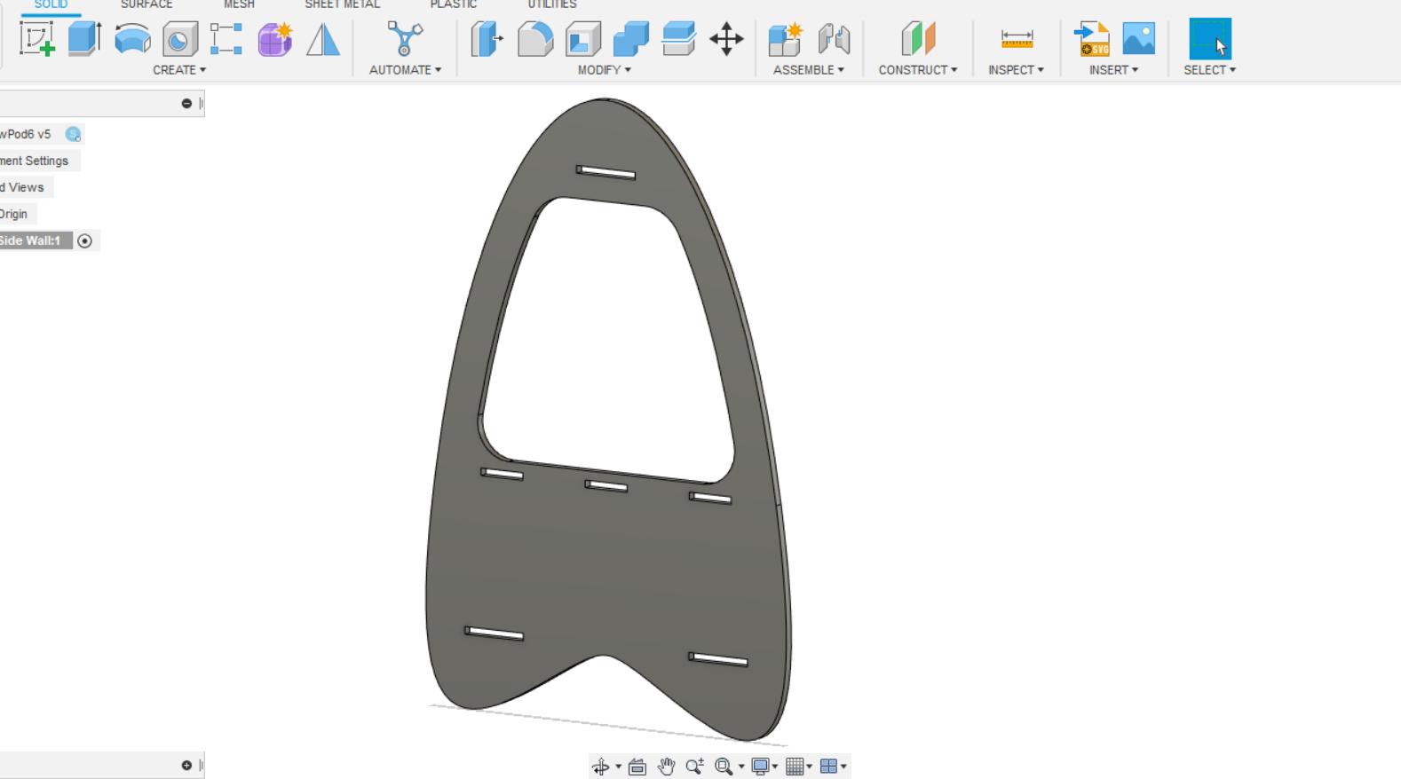
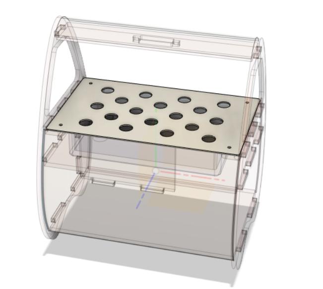
I realized that I needed three rows the top one needs to hold the lights , middle one the grow try and the bottom one mixing chamber and electronics .
Mirroring The Vertical member and adding the panels between .
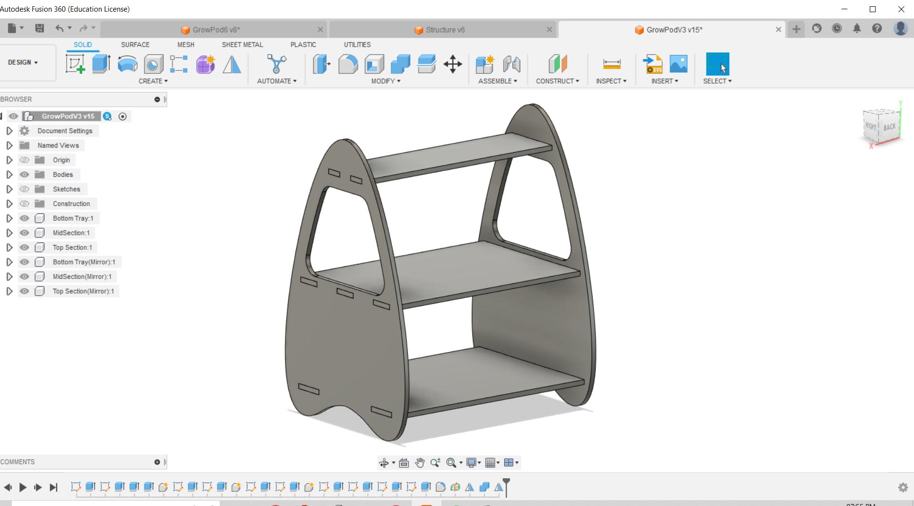
I incorporated each element as individual components, allowing me to conveniently toggle their visibility on and off while designing other components.
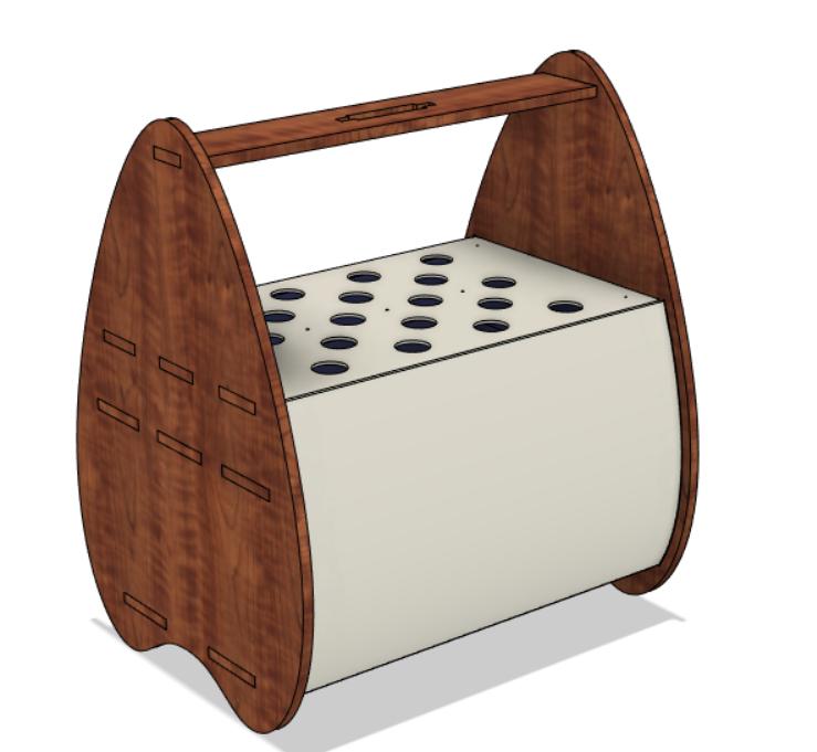
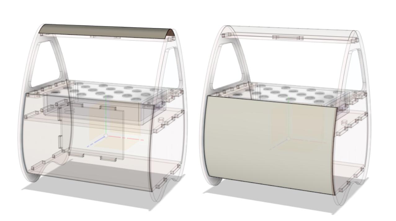
Final Design The two Blue components are trays that are manufactured separately .
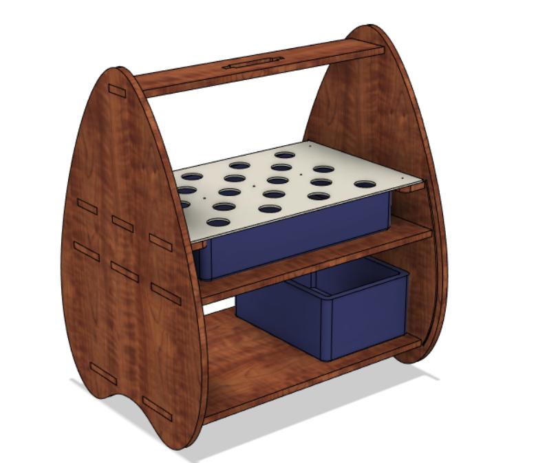
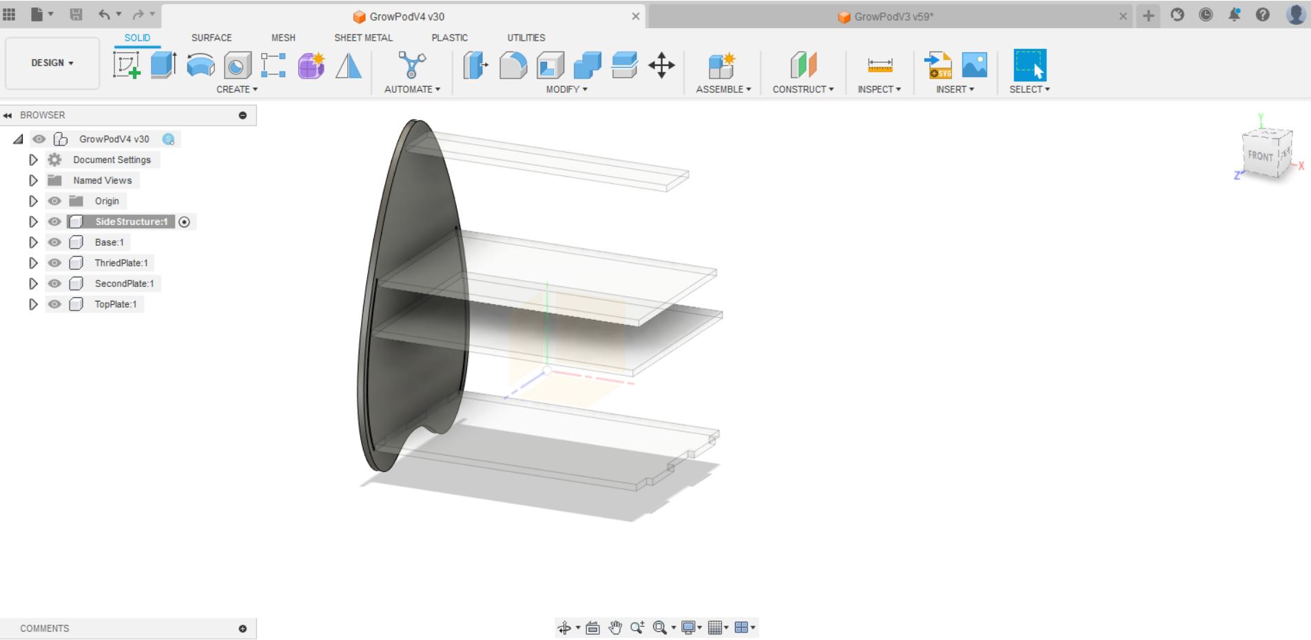
After adding cover to the design
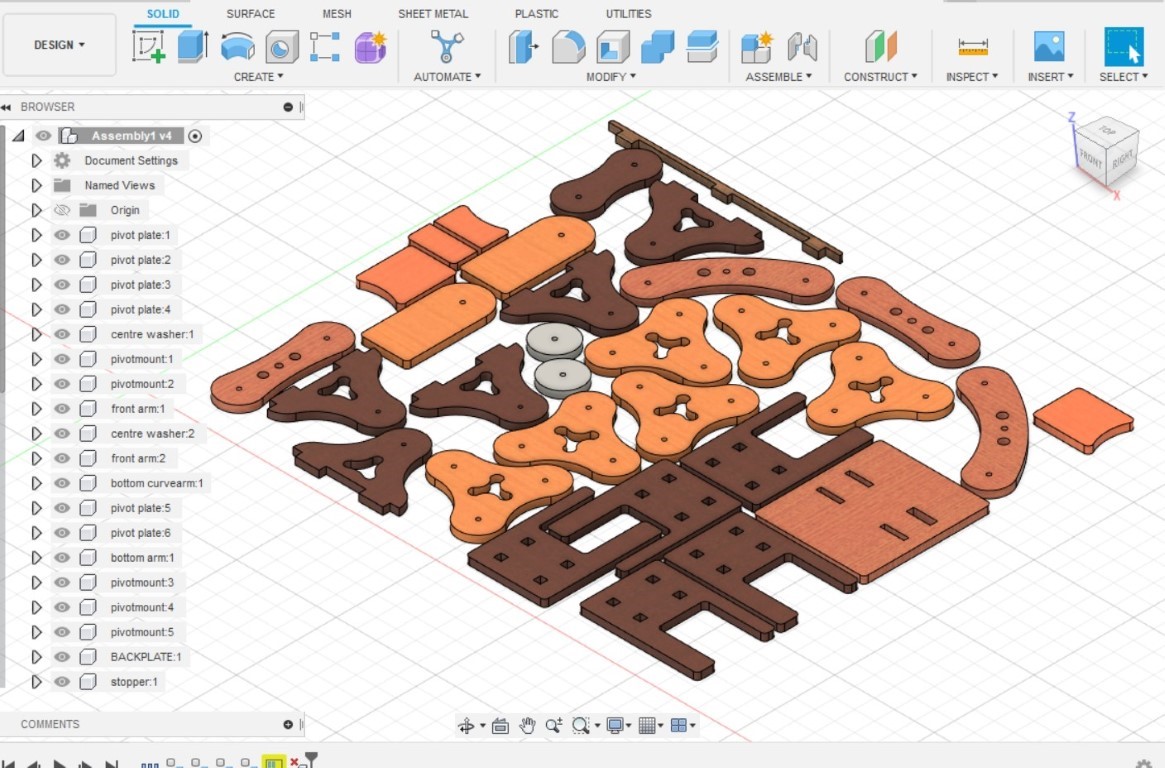
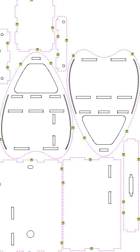
Arranging The design to a flat pattern .
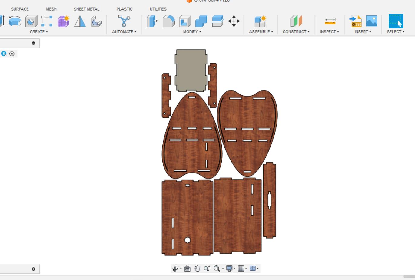
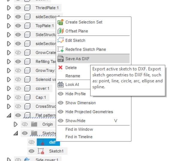
To streamline the design process, I projected all the components onto a sketch using the project tool in Fusion 360. This allowed me to work with a comprehensive reference of all the elements while designing the stand.
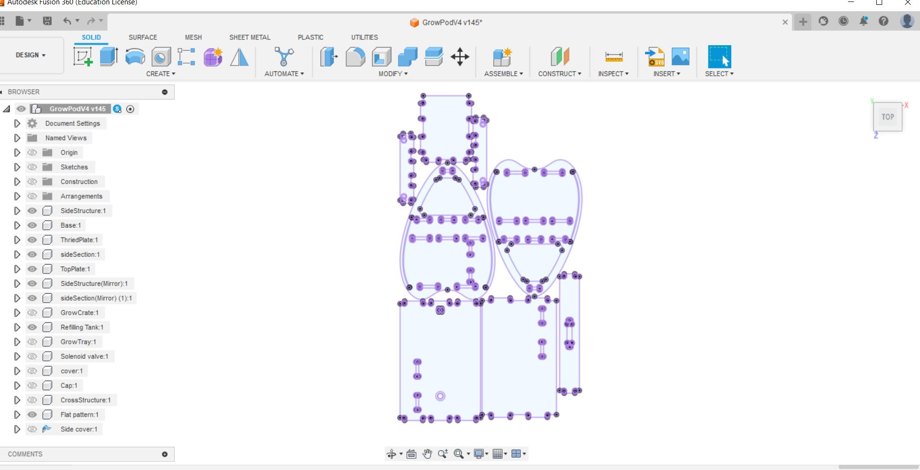
By simply right-clicking on the sketch, there is an option available in Fusion 360 to export it as a .dxf file. This file format is commonly used in Shopbot, a CNC (Computer Numerical Control) machine, for further processing and manufacturing purposes.
Laser cutting a scaled model
It is recommended to create a cardboard prototype before cutting the actual plywood to ensure accuracy and avoid any mistakes in the original design. I utilized the scaling tool in Fusion 360 to adjust the size of the existing projected .dxf file.
The thickness of the scaled model should match the thickness of the the cardboard.
3mm was the cardboard Thickness to ensure maximum fit I made the thickness to 2.7mm.
Once the .dxf file was exported onto a USB drive, I proceeded to open it on the PC that was connected to the laser cutter. Subsequently, I accessed the file using Rhino software.
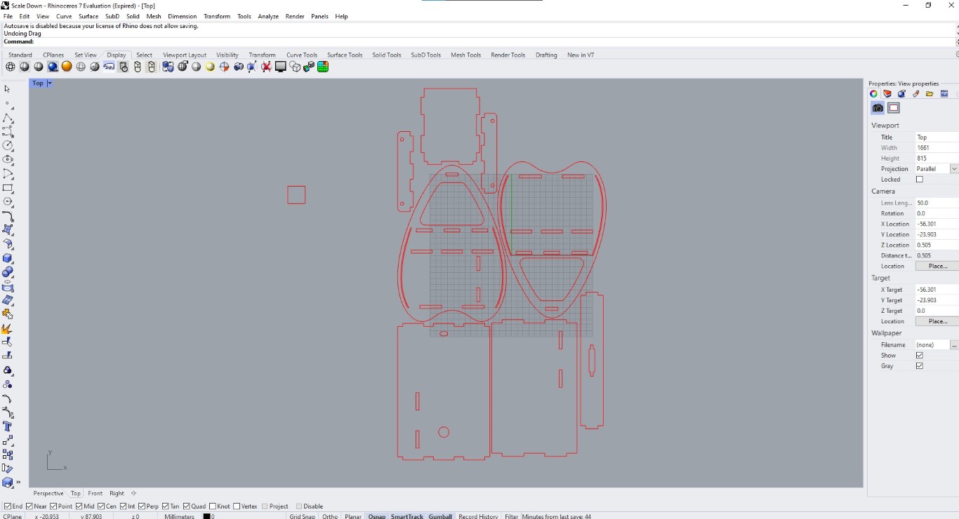
In Rhino, component selection is accomplished by dragging and selecting, which then forms a group. On the right-hand side, you will find the properties associated with the selected components.
Line Type and Print width should be continuous and hairline respectively .
black is used for engraving
purposes, while the color red is utilized for through
cuts.
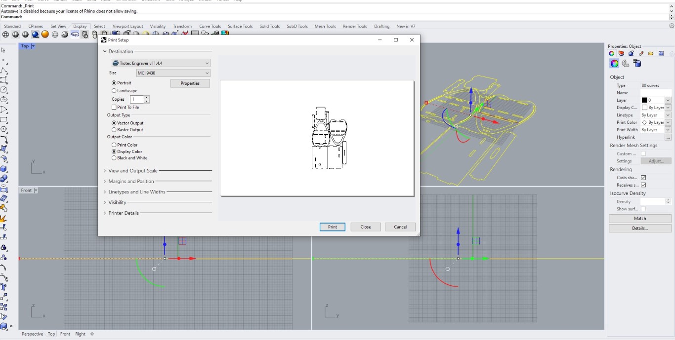
When transferring a file to a Trotec laser cutter or engraver, the typical method is not through the "Print" command but rather by using dedicated software or specific file transfer methods. Trotec laser machines often come with their own proprietary software, such as JobControl, which allows you to import and manage files for laser cutting or engraving.
After dragging the design towards right under jobs and then right clicking the same to edit .
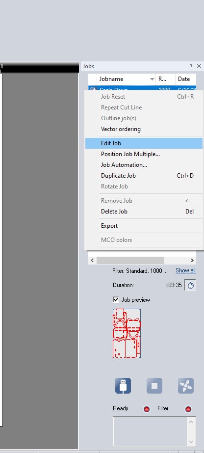
It Opened on Job control Cut
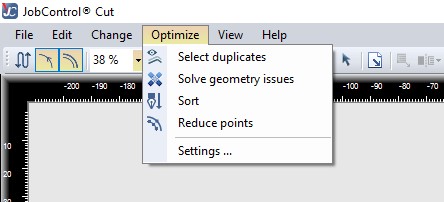
In job control Cut make sure that there is no duplicated lines and all geometry issues are solved suing the below commands .
After giving the appropriate power and material
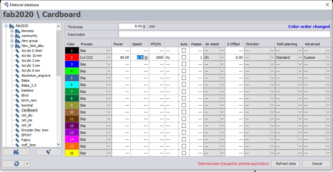
I utilized the Trotec Speedy 300 machine at our lab to cut the card board.
All the individual pieces from the Cut
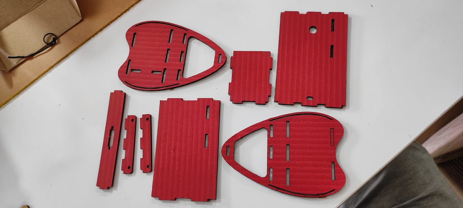
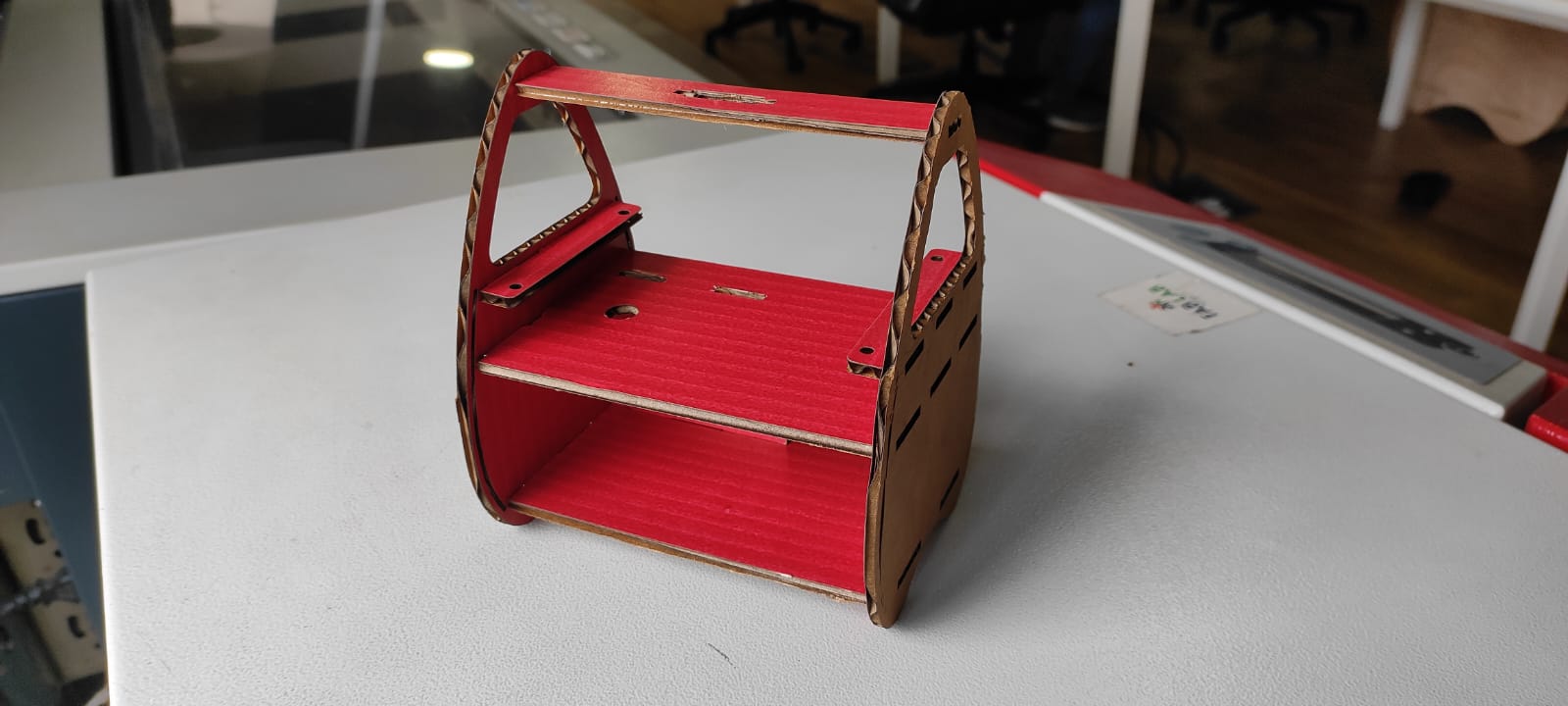
Final Assembly
V Carve
What is V carve ? 🤔
Once I had the .dxf file, I saved it onto a USB flash drive and subsequently transferred it to the PC that is connected to the Shopbot.
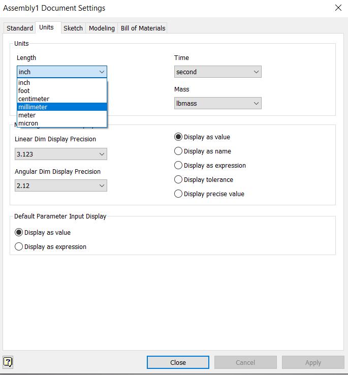
In V Carve software, the "Job Setup" refers to the process of configuring the parameters and settings for a specific project or job. In the context of our project, the Job Setup in V Carve entails specifying the dimensions of the plywood material. Specifically, we defined the width and length as 2440 mm and 1220 mm, respectively. To ensure precision, we manually measured the plywood's thickness and determined it to be 18.1 mm.
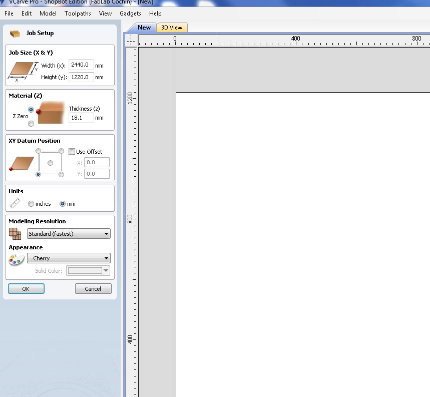
XY datum, also known as the reference datum or coordinate datum, refers to a specific point or location used as the origin or starting point for establishing the X and Y coordinates in a coordinate system. It serves as a reference point from which all other positions or measurements are calculated.
Toolpaths
There are various Tool path offered by V carve we will be generally using the Pocket and Profile Tool paths .
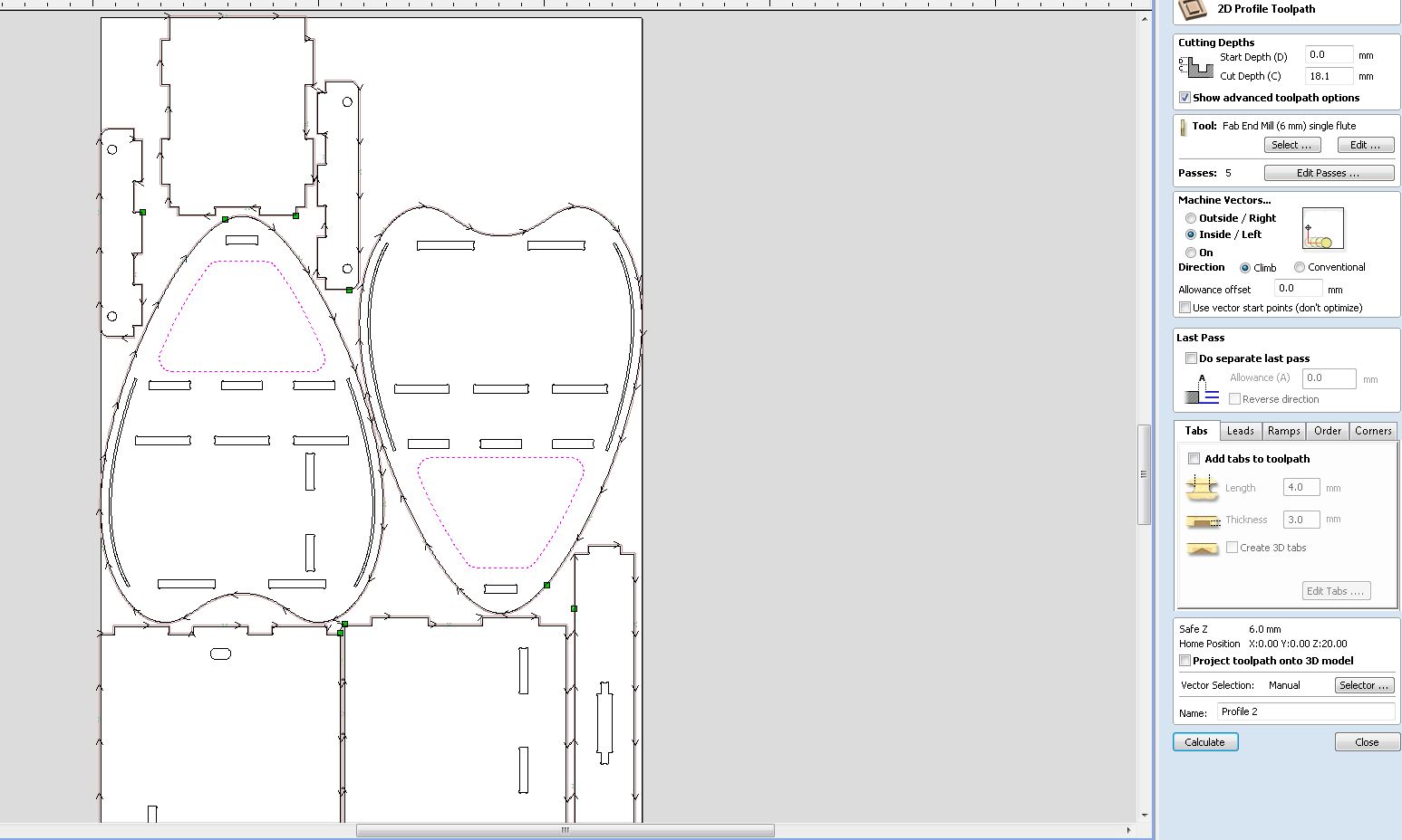
Following are the setting on a 2D profile tool path .
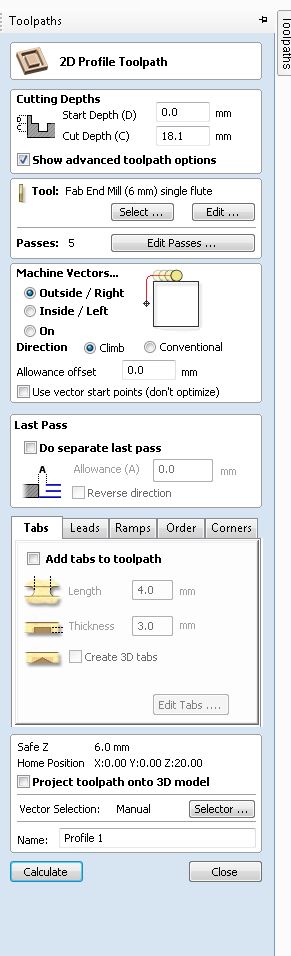
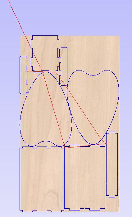
Selecting the Profile outline .
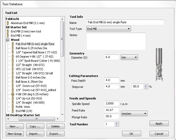
Upon selecting the appropriate tool, we are prompted to choose the tool for profiling or performing the cut-off operation in V Carve. In this case, we opt for a 6mm End Mill as the tool of choice for the profiling task.
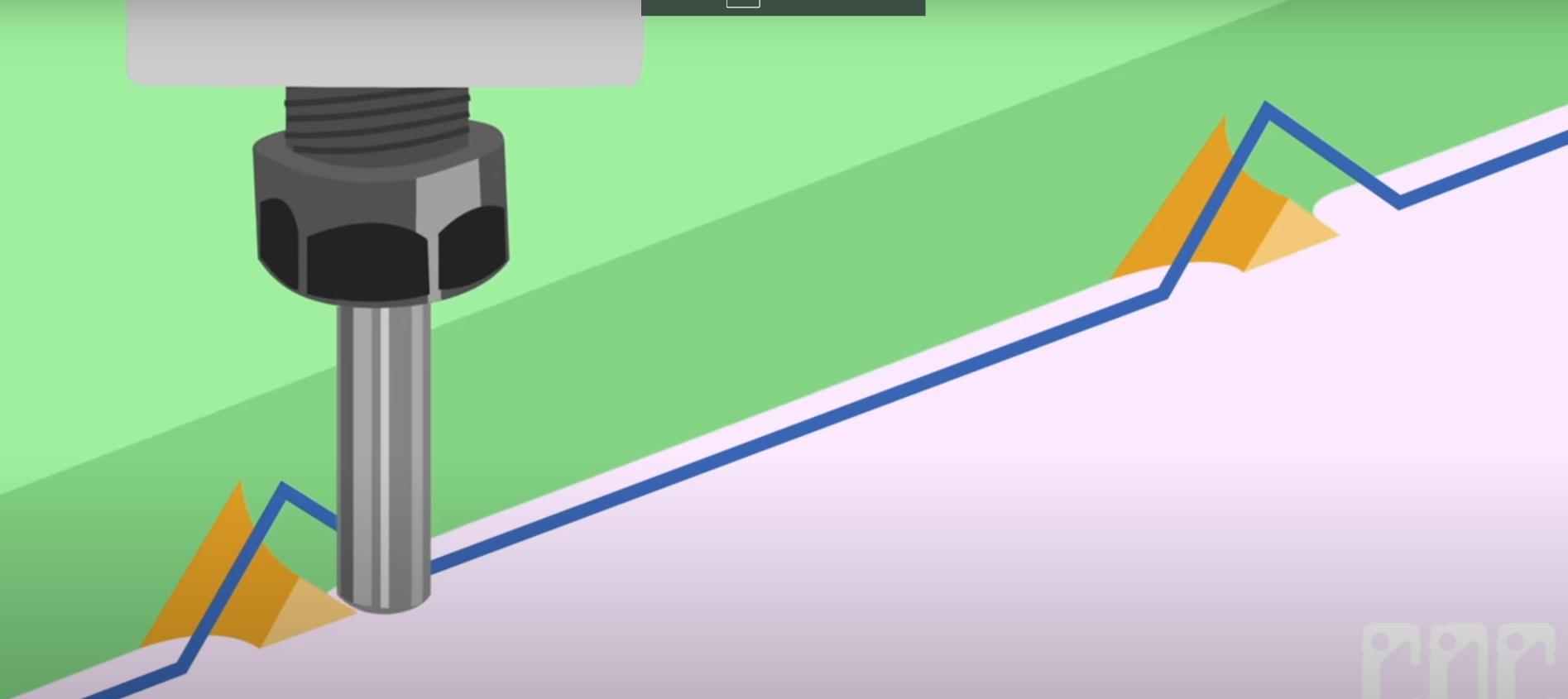
Tabs
Tabs are small connecting pieces or bridges intentionally left in place during the cutting process to hold the workpiece in position. They are typically thin and narrow sections of material that remain attached to the main piece, acting as temporary support.
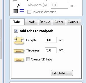
Following video explains Tabs in detail.
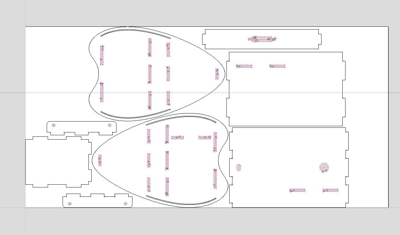
After calculating the profile Toolpath .
Reentered cutting path
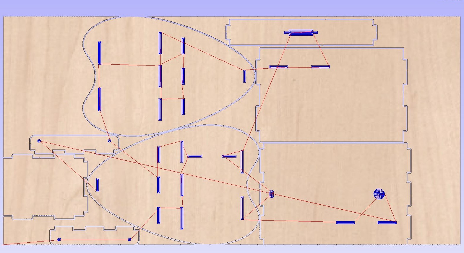
Once I had selected all the pockets that needed to be cut, I proceeded to utilize the pocket toolpath in order to execute the cutting operation.
After processing the pocket tool path
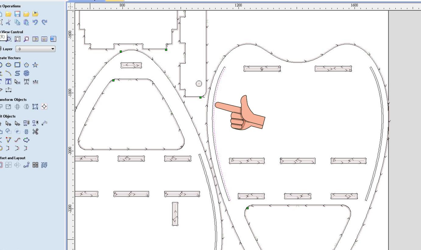
For the pocket located on the side where I plan to place a sliding cover, I did not require the tool to make a through cut. Instead, I needed a depth of only 10 mm using a 3mm bit.
Due to the vector not being closed, the selection process was incomplete and it did not encompass the entire shape. 😢
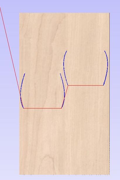
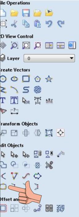
To merge all the lines together, I utilized the combine tool. Below is a description of how the combine tool functions.

I used a 3mm bit to cut the following profile ( inside cut ).
Final 3D view after calculation
As a final step, I divided the inner cut profile into a separate toolpath to ensure that it is cut first before the outer profile. This approach allows for proper sequencing and precise machining of the inner profile.

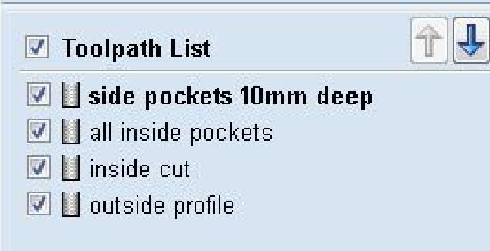
Properly arranging the toolpath sequence is crucial for effective machining. By carefully organizing the order of toolpaths, we ensure that each operation is executed in a logical and efficient manner. This allows for optimal material removal, minimizes tool changes, reduces machining time, and ultimately contributes to the successful completion of the project. I chose to machine all pockets first and the profiles later .
Error ! 😔 When attempting to save the toolpath, I encountered an error indicating that there were profiles with different tool settings and the sequences did not align properly. This discrepancy in tool configurations and sequencing became apparent, leading to the error message.
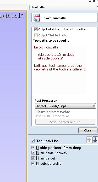
In order to accommodate the tool change after the 6mm cut, the 3mm toolpath had to be saved separately as a different file. By deselecting the toolpath that required the 3mm pocket and then specifically selecting the 3mm tool, I successfully achieved the desired outcome.
Finally export the File Toolpath list as
shopbot .sbp file .
Machining
The details of the Machining Setup have already been documented in the Group assignment. For further information and specific details, please refer to the provided documentation.
Fixing the Plywood to the sacrificial mdf board by drilling and screwing .
Setting the z axis reference to zero ( refer the group assignment page for more details )
Cutting outside Profile
Cutting Pockets (Step cutting operation )
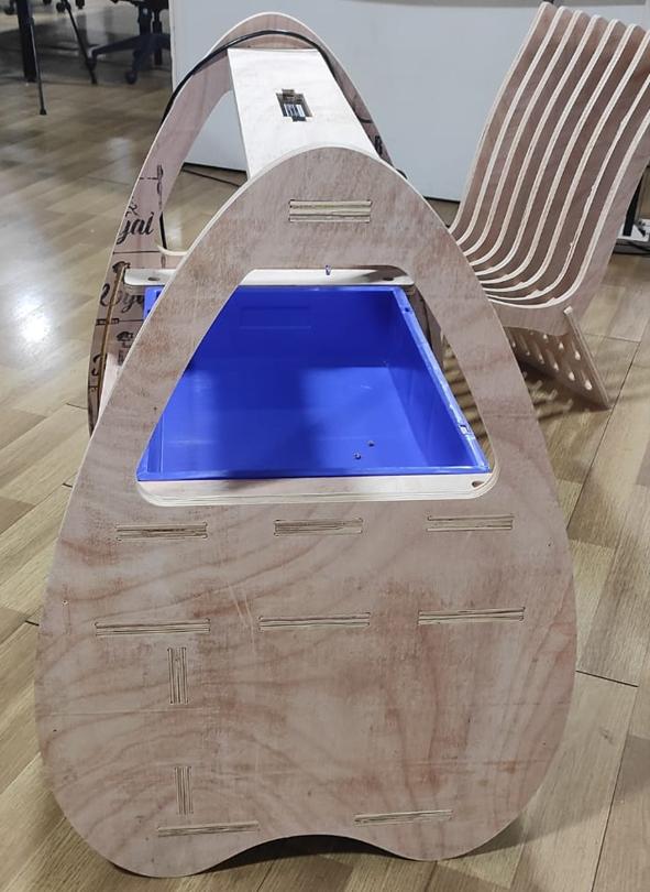
Assembling The Workpiece
As a final step in the assembly process, I created a trial run for the covers by cutting them out of cardboard material. This allowed me to test the fit and alignment before proceeding with the actual assembly. ( yet to decide the mover material )
.jpeg)

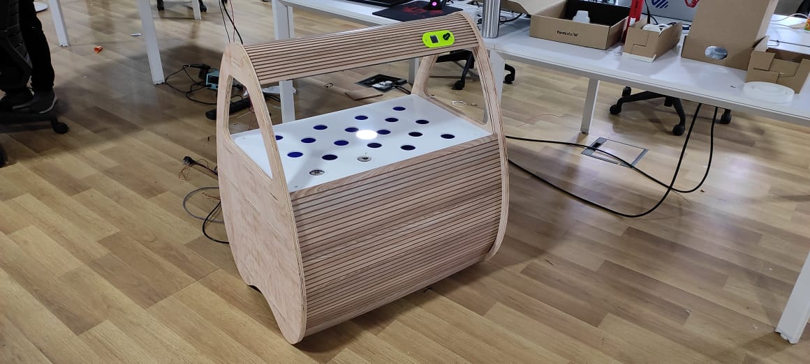
After placing light and Trays
.jpeg)
Project Design Update
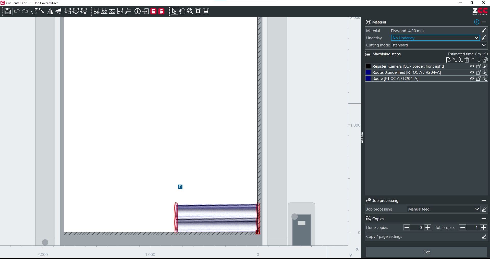
This week I thought of making 2 additions to my hydroponics project . A cover for the structure and and a grow tray for the bucket to hold . I thought of milling out the design on zund .
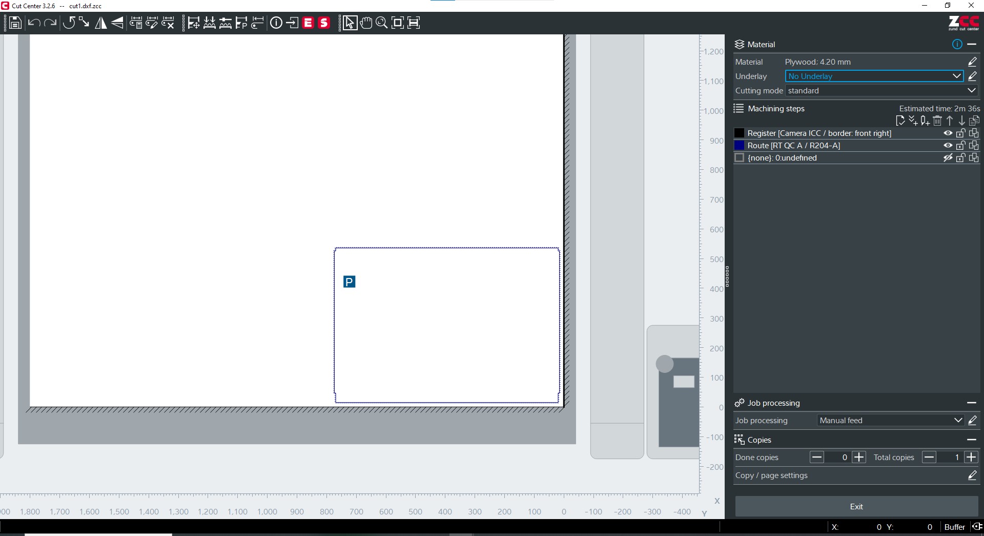
The outer profile After exporting the files from fusion 360 as .dxf i did the cutting using the zund Router Module
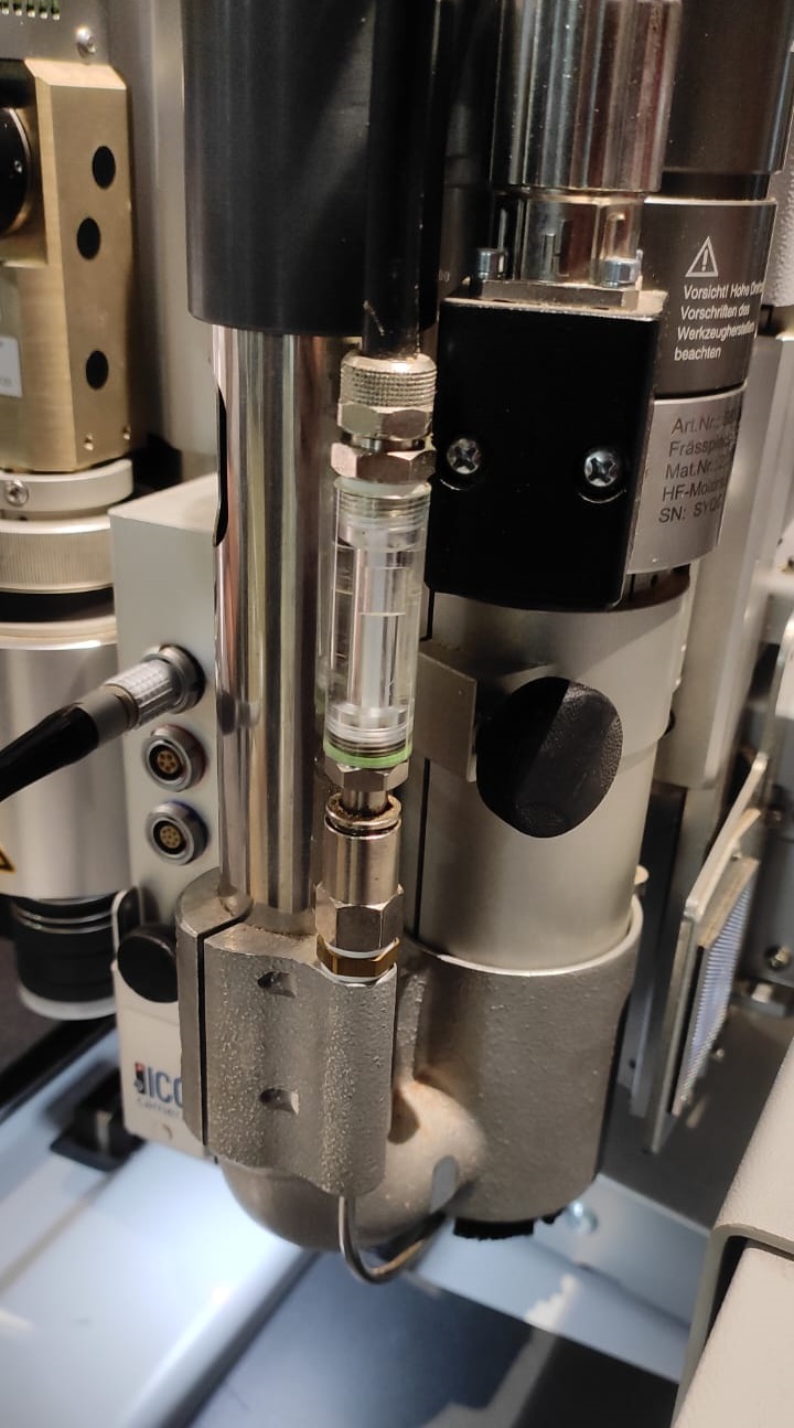
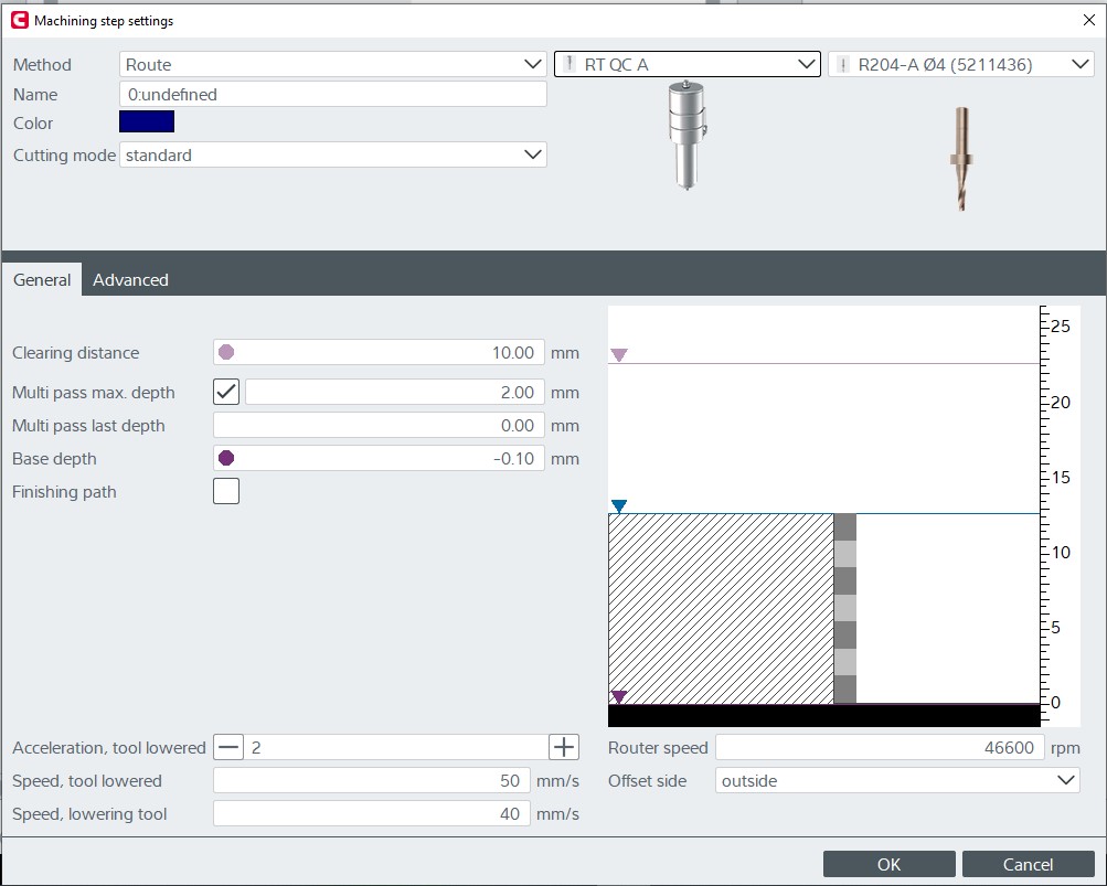
For this task, a 4 mm cutter was utilized with the Router Module. The depth of the cut extended 2 mm from the bottom surface upwards.
Our instructor jogin had already tried Kerf-bending the material (pre-laminated MDF ) and the pattern is very effective.
click here - you tube link to learn more about kerf bending
Outer Profile of the cover .
Kerf hole milling design
Following is the depth of cut Speed and feed setting that were given for the cutting .
Final cutting
Assembling the the Front Cover and Top cap
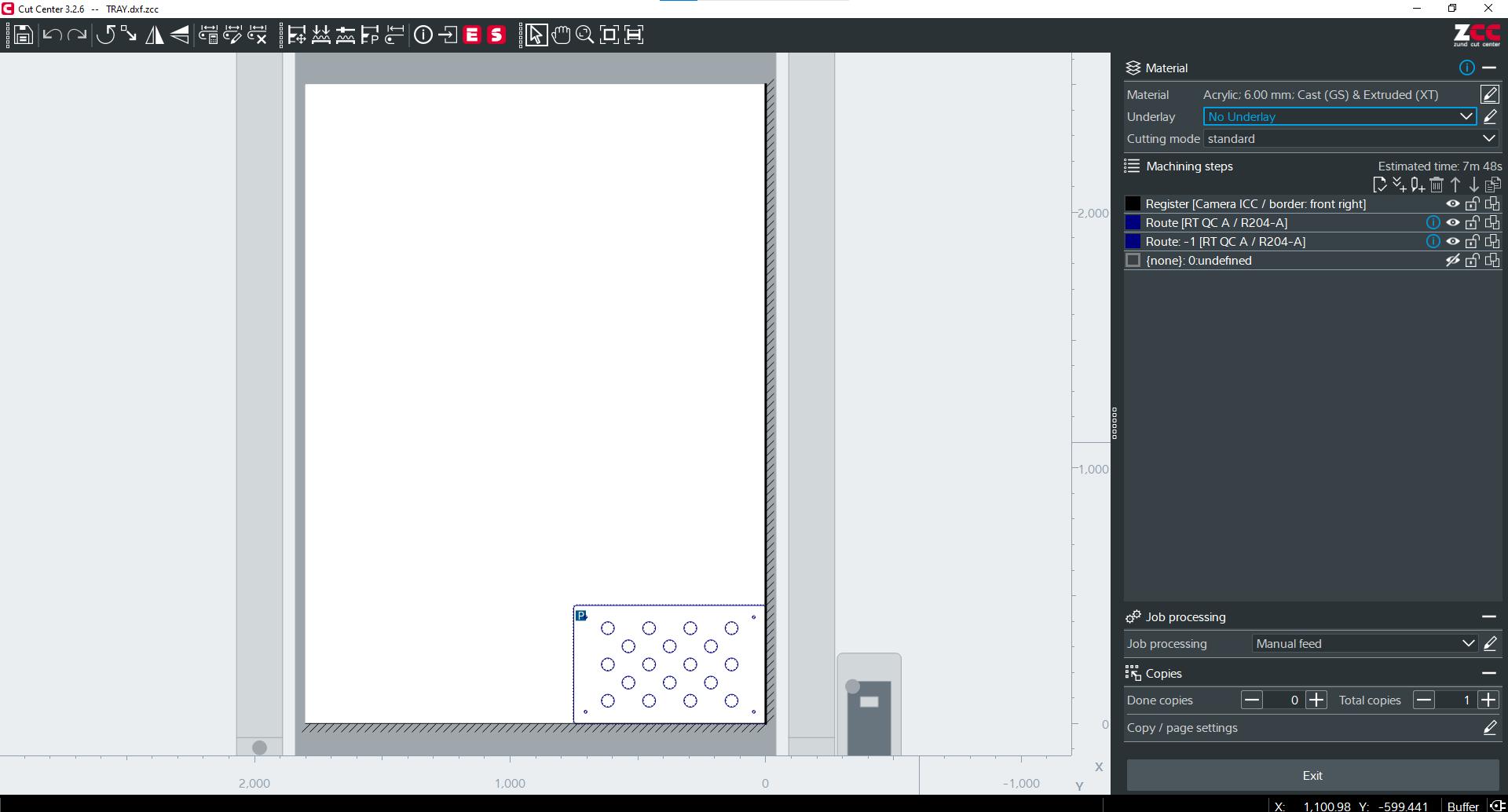
from fusion 360 to cut center ( grow tray )
Grow tray Hole cutting on acrylic .
Final Assembly
Resources and Downloads 📩
📩 ShopBot files for milling📩 Growpod shopbot dxf file
📩 Workstation step file
📩 grow pod project .dxf files