𓍊𓋼𓍊 FINAL PROJECT 𓍊𓋼𓍊

In Japan there is a word for sunlight as it shimmers into the forest through the leaves:


彡 ╰⊰✿´ 彡 ╰⊰✿´ 彡 ╰⊰✿´ 彡 ╰⊰✿´ 彡 ╰⊰✿´ 彡 ╰⊰✿´ 彡 ╰⊰✿´ 彡 ╰⊰✿´ 彡
Ever since I was a little girl I dreamed of magic.
And I never meant parlor tricks, I meant genuine magic, which felt so connected to nature. I wanted fire to burt from my finger-tips. For wind to obey my commands, I would hear whispers between the leaves and shadows in the corners of my eyes.
My desire was selfish, but it was all-consuming; to be included in the wider communications between nature, technology and also myself. I spend my childhood imaging myself being able to interact with trees and plants, for them to sense my presence and for me to be a part of them. I became a filmmaker to be able to bring these worlds to live, but I became an artist to bring the feeling to life.
As I plunged into technology and speculation and immersive installation, the more technology seemed like magic to me: A science of the unseen.
As I grew up I started finding magic in other places. No longer just in the things that I could force to submit to my will, but in those those that would not. The universe beyond my desire became both calming and an obsession, to meld into to, to hear it, to slowly disburse into the whispers of existence around me.
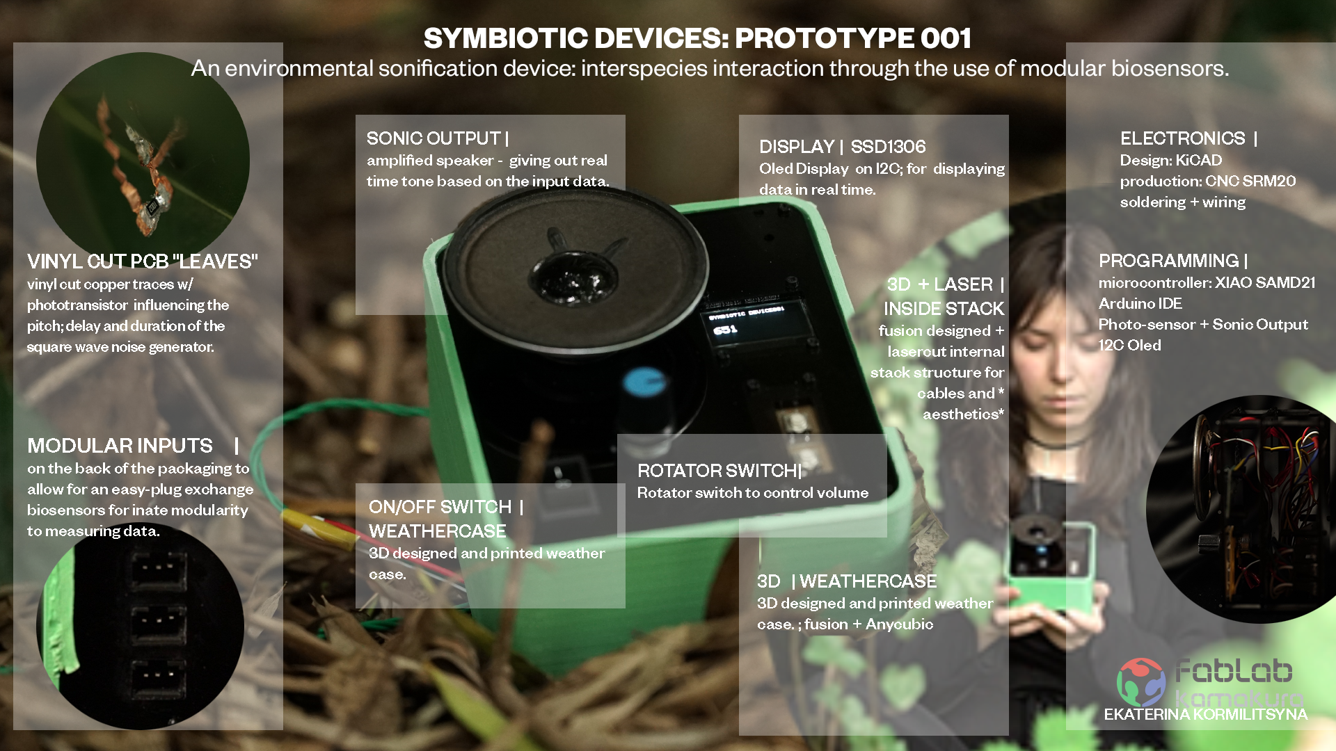
"SYMBIOTIC DEVICES" HERO SHOTS


Concept
Symbiotic Devices: PH0T0SYNTH is a small device which sonifies the plants interaction with sunlight. Playing with the process of photosynthesis and inter-species-communication this devices whilst allowing the player to interact and collaborate with the bio-processes of the plant, ultimately asks the questions whether the plant should be left to it's own devices- giving us simply the opportunity to observe the whispers of the forest as it communicates.
YOU WLL GAIN:
A modular sonification device to listen to the whispers of your environment with modular-input bio-sensors.
YOU WILL LOOSE: (BOM)
| Material | Amount | USD | YEN | LOCATION |
|---|---|---|---|---|
| BOARD | ||||
| Seeduino Xiao | 1 | 6,05 | 850 | link |
| 0Ohm Resistors | 4 | ¥1.6 | fabinventory link | |
| MOSFET P-CH 30V | 1 | 1,57 | 220 | link |
| ~~2ndHand Vintage Speaker~~ | 1 | (ended up not being implemented in FP) | ||
| Speaker 8Ω 0.4W | 1 | 1,28 | 180 | link |
| ~~TRRS Audio Jack~~ | ~~1~~ | (ended up not being implemented in FP) | ||
| DiyStudio I2C OLED | 1 | 3,56 | 500 | link came in a two-pack, this is a chinese dupe for the original SSD1306 model |
| ~~Neopixel~~ | ~~9~~ | (ended up not being implemented in FP) | ||
| INPUTS | ||||
| Phototransistor | 3 | ¥35.2 | fabinventory: PT15-21C/TR8 | |
| 10 Ohm Resistor | 3 | ¥1.6 | fabinventory | |
| SWITCHES&BUTTONS | ||||
| TACTILE BUTTON | 2 | fabinventory | ||
| SWITCH ON/OFF | 1 | link | ||
| PACKAGING | ||||
| PLA- fillament for 3D printing | fab-inventory | |||
| PLEXIGLASS A4 sheet | 1 | 10,68 | 1600 | link |
| 2M Spacer and screw set | 1 | 9,50 | 1335 | link |
| WIRING | ||||
| 10M roll of wire - green | 1 | fabinventory | ||
| various small cables used to internal communication | ~ | fabinventory |
INSPIRATIONS
It all began with this paper I came across a couple years back. https://www.cell.com/cell/fulltext/S0092-8674(23)00262-3.

This paper has been floating in my head since the first time I read it, it has been Since inter-species design had been at the core of my research I had engaged with alot of previously conducted work, by other laboratories trying to interact with plants.
It was a key piece of motivation for me to not simply map random noises onto sth like some other companies to (cought cough plantwave)
RESEARCH
I have researched many various pathways for this project. This research can be viewed on a seperate page HERE.
SPIRAL DEVELOPMENT

SCHEDULE
I pre-worked multiple aspects of this project as I the weeks went on, and so now in the final weeks only a some things still needed completing. Also in the spirit of spiral development and re-search oriented structures.. I did have big plans for this device, but in the face of time pressure and certain things not working, I could always fall back onto code and attempts that I had tried in previous weeks and implement these things in the previous weeks.
| DETAILS | WEEKS |
|---|---|
| You can find schedule things of what has yet to be completed here in Week 19: | WEEK 19 |
| As a summary from that week I outlined which things I had successfully completed as experimentation throughout the 20 week course, and what was left to do in the final weeks: | |
| INPUT + OUTPUT DEVICES: NOISE MUSIC DEVELOPMENT built the basecode for the symbiotic device prototype. | WEEK 09 |
| WEEK 12 | |
| MOULDING AND CASTING; i tried to use this mould to make a button for my synth.. but it didn't rrly work ahah | WEEK 13 |
| NETWORKING; this built the base code for the utilisation of OLED screen inside my device | WEEK 14 |
Fabacademy dominated my life so much I once started drawing my mind-maps on my livingroom windows to try and figure things out

ELECTRONICS DRAFT - PINOUTS
So in order to fullfil my spiral development aims as well as my own personal desire for the project I need to make sure that certain elements are incorporated in the design of the electronics.
So first I made sure I had enough Pin's for what I wanted and made a little sketch to refer to for myself for the pin-outs.

The LED'S and the BUTTONs for now remained for the next spiral of code-development, but I already incorporated them in the designs and pin-outs so that I wouldn't have to design the board or the box again. When I would be ready I would only have to focus on the code.
FIRST SKETCHES
In my first Week had found some preliminary sketches and inspirations but since then I had worked through further research to understand which direction I wanted to take the design of this project. I needed something to combine the modular synth aesthetic and functionality with natural elements of bio-sensor. A bio-synth quite literally.

Using DALL-E I decided to inspire myself by generating some images to see what computer vision imagines when confronted with my idea.
Prompt: create a sketch, design or model of a modular syntherizer which plugs into and sonifies nature


3D MODEL // VISUALIZATION
INSPIRATION
When I started thinking about how I wanted to my final object to look like, I found my primary inspirations from two sources, a second hand shop here in Japan and AI generated instagram posts. These two have more in common than you might originally think.
As can be gleaned from my notes in the very first week I have a somewhat scizophrenic mind. It is a struggle for all of my project as the ideas rush around my head so quickly I struggle to make them stop for long enough for me to even understand my own thoughts, but as much as my Final Project kept changing ( constantly in search of something deeper, more impressive, more poetic or more inventive) in that very first week I had set the tone for an aesthetic that in the end, here were are faced with it full circle again. I was chasing an aesthetic that merged 80's/90's video game and anime aesthetic with current trends of minimalism and futurism. While this might seem like an attempt to merge maximalism and minimalism- thats not quite the case, as the aesthetic of 90's anime nad video games, also in large part strove to visualize an idea of futurism.
After going on my fabacademy journey... changing my mind 5-thousand times and creating a thousand different ideas for my final project ( in fact I made a whole wiki-page for all the idea's I ended up not pursuing. )
But when trying the visualise the final shapes I first turned to instagram


And for further visual inspiration I went to HARD OFF, which is a second hand store here in Japan that I'm kind of obsessed with. It's heaven on earth, ahahha.


For a second I thought to maybe use some of the early 2000's waterproof camera-cases, and simply adapt my device in a way in which it could somehow assemble it on the inside of these boxes and already utilize the placement of the buttons which are already designed into it.
And part of me still thinks this would have been really cool, but I in the end was inspired by another structure. BioClub is one floor underneath SAFECAST which is a volunteer organization which build geigercounters and much much more. The guys running it, kindly allowed me to solder my things upstairs in their work-stations when I didn't want to go all the way to Kamakura, and they also let me take apart some of their old prototypes in search of bits and bobs to include into my prototype... and thats when love struck.


What I did realism from all of the other things that inspired me is that i LOVE acrylic and glass... so guess in the future i gotta find some ethically and ecologically conscious way to create something akin to acrylic.
SKETCHES
So I sat down and sketched by hand this time.


CARDBOARD PROTOTYPES
Then I replicated the layers in cardboard to see if the futuristic game-boy aesthetic still worked despite the added width to accommodate the speaker.


During the cardboard prototype I realised that the volume control rotators should be at the front if I want the stack structure to be visible and stand-alone and the outer-enclosure only to be attached for weather-proofing.
INSIDE-STACK DESIGN
I started designing the interiour stack in fusion360, just by creating dimension paramters for each of the acrylic layers. I used the cardboard protoype as a measuring guideline, because I could just basically punch all the components through the cardboard where I wanted them to sit, and then simply measure the holes and distances and directly input those into fusion.

And then I went ahead and started designing.


THE PCB's
MAIN BOARD
My goal for this design is simplicity, so rather than going in the design direction that I went into with my prototyping board throughout the course.
So I simply broke out all the pins on my board as many times as possible, so that I could later connect anything


MILLING We know the drill, we've done this often.. we go, we deal with mods, we hate our life, we mill, we succeed. Gotta say it's pretty fun that milling and making boards used to take me a whole day and now it's like an hour. Designing is still a bitch, but I shortcut by re-using the overall trace design for the Light-sensor and the speaker from


I did make two boards.. one at the beginning of the week to start testing, one half way when I was also milling the additional board for the buttons. on that board i removed the copper and also drilled some placement holes so that the board could be fixed securely inside the stack-structure.

The output = The speaker, connects directly into this main board.
BUTTONS
The buttons in this case, to the moment of the presentation we're not yet coded to be functional, but I had designed and milled their board so that it could be included in the construction of the prototype physically, this way their inccorperation is just a matter of code.


NEOPIXELS
The same thing that went for the buttons, was also true for the neopixels, but I actually made a mistake in that board, so I ended up not utilizing it at all.. and I'm actually happy about that. I think the prototype doesn't benefit from the addtion of neopixels.
But here was the faulty design.


BIOSENSORS/ INPUT MODULES / TRACES
Please read my full bio-sensor research on my research page. There I keep all the ongoing information about multiple sensors, and how I could implement them for various interactive purposes.
aswell as all my experiments which I outlined in
After these experiments, I settled on using light-sensors for this iteration of the device, but designing the plugs for the input-sensors on the back of the device in a modular fashion. This way the inputs can be easily exchanged based on what type of plant or bio-mechanism I am trying to engage with. This will also allow me to interact with various inputs in the future further establishing this an expandable patch-device. After all, patch-synths were a key inspiration.
I enables this patch-function by crimping my own cables and adding conectors to the inputs, the extention cables aswell as the device itself. It was tedious, but this way it all became a realitively secure plug'n'play set-up.
LightSensor: WEEK 12
This has been the sensor which I had explored most in all my weeks at FabAcademy.

So for this particular input it was important to me that the input became one with the plants. So I knew from the very beginning that I would not require a board from the these inputs, but that I wanted to achieve something more ephemeral.
The solution in my mind was Vinyl cutting.
Cutting PCB's so that they would be flexible and thin was an idea that had been floating in my head for a while. Originally I thought I could then embed the whole thing into thin silicone that I had made during WILDCARD WEEK. But this actually didn't work, because the copper somehow refused the bind to the silicone. This was a shame cos in the future I wanted to use this process to attempt to do skin-electronics... but for this particular attempt it was ok, because leaving the copper loose meant that I could attach the traces directly to the leaves, and I found that very poetic.
BUT BACK TO THE VINYL CUTTING: I hadn't tried it before, so I had to do some tests. I also brought two different kinds of larger metal tape... but ultimately came to the conclusion that copper soldered better.
Test on normal vinyl to check thinckness:

2nd test on cheaper metal

final cut making multiple input sensors

soldering the light-transistor and the resistor to them


and then soldering wires to them which then got crimped into the connector.


I made like 5 of these, just in case some break cos they are so sensitive, but i store them between sheets of silicone so they ended up pretty safe.
WIRES & CONNECTORS
I spend like a day making these, so I want that to be clear ahah. In order for this whole thing to be modular I needed to make connectors, but also because the inputs needed to interact with sunshine while the device was in my hand, I also had to make cables... really long cables, because I wanted the inputs to be really high-up in the tree's.
So I added connectors in multiple places: this way the actual input could be connected either directly to the device, or to cables of varying length.
The connectors I ordered on amazon at first, but then for the ones inside the box I simply used connectors which were already connected to cables and I simply stripped those and soldered them into place.
look at those tiny adapters...
and then I made cables.... 3 METER cables.. twisted and everything... I made them green so that it blends with the tree


I twisted them using a handdrill...so i kinda realised it's best to overtwist them- and then you kind of release them, tape them up and shake out the overtwisting so that they don't coil up on themselves.
But the signal was nice and clear and functional so yay.
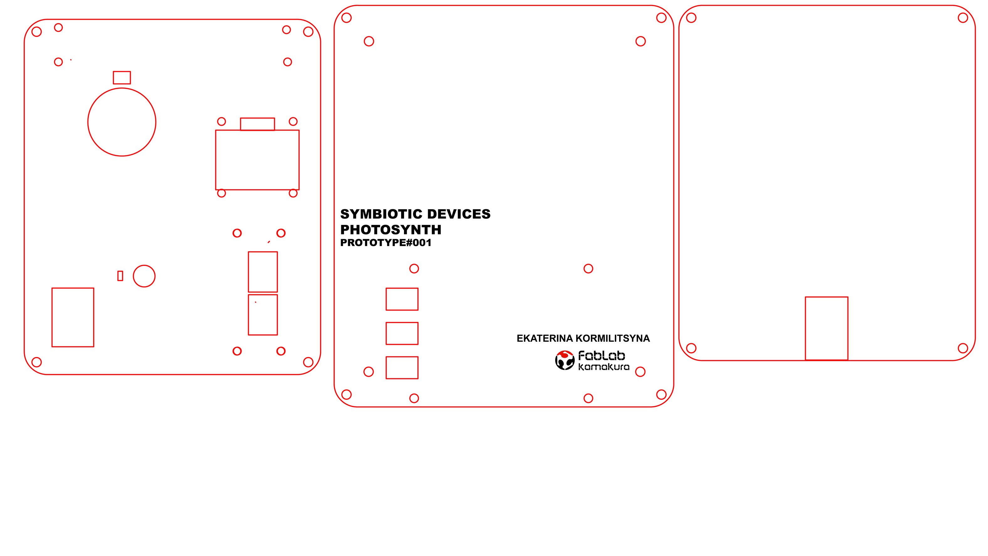
THE OUTSIDE// THE STACK
This section kinda goes hand in hand with the previous visualisation design where I had already started desiging and setting the pramaters for the interior stack design in Fusion360.
Once I had the finished paramaters and sketch-layers, there wasn't really need to 3D model the whole thing... I knew the acrylic layers would be lasercut: so I knew that the only thing that would require modeling and extruding would be the outside weather case.
So once I had everything done in Fusion, I exported the sketch layers as .dxf to Illustrator. There I finalised and prepped the design for cutting and I also added the text that I wanted to be engraved aswell as the placement of the cable-management holes in the middle layer.


LASERCUTTING
I had to go back and forth a couple of times on the lasercutting back to illustrator to make sure all the holes for the components had a snug fit.
First I had to change filters in the Lasercutter in Kamakura, because we keep an aditional filter for the wood, and over all Youka-san asks us to avoid cutting acrylic in kamakura


Now that thats done, on with the laser-cutting


2nd iteration backplate: Look at the little plugs for the input-cables to be plugged into.. so neat.


and on the middle plate a little secret for those who were around since the week1 ascii funsies ;)


3D MODELLING
Back in Fusion 360, based on the sketches i did for the inside-stack. I take the same line and offset it to make the same shape slightly larger.

Then I extrude it and also make sure that there is a gap for the electricity supply.


3D PRINTING
Firstly I had to 3D print some 3M spacers because the ones I had ordered on instagram weren't arriving in time because a typhoon had delayed them.
I didn't want to waste time on modeling them, so I just quickly grabbed a model from here

This kinda didn't work so I ended up ordering them on Amazon. It was a dissaster ahaha.
But I also still needed to print the outside-weather-case that I had designed in the 3D-moddeling session:

MOULDING/ CASTING (BUTTON?!)
I attempted to use the gummi bear mould from the moulding and casting week to try and make gummi-bear shaped button out of silicone. but dang. it was just a bit too big.
I had to make a new mould from the wax cast- this time using plastic- since i wanted the final output to be silicone- so the mould had to be not silicone.

to get the plastic out of the wax- I used a demoulding spray this time, and gross, eww it kinda fucked everything up. I tried it on the blue silicone and it made it not dry and stay horribly tacky forever.


I think if I were to re-attempt this, I would 3D print the mould ready for the silicone already.
I also tried to cast silicone in a silicone mould using demoulding spray, but oviously it still sealed together.
ASSMEBLY, SOLDERING AND TESTING.
Now that most of the part existed by themselves it was time to beginn assembly and debugging to check if each part worked.


During soldering I implemented my ***colour coded wires*** to help me with my cable management!!!
WHITE/YELLOW : PIN CABLES
RED: POWER CABLES
BLACK: GND CABLES


On the modular plugs for the inputs the PWR cables were GREEN, simply because that's how the plugs came.

During the soldering I also realised that there was some-kind of issue with my speaker and mosfet-combo ( yes once again!! )
I don't really understand why it acted, up but I just turn it upside down again and it worked... but also.. it didn't increase the volume in any noticeable manner. So who knows whats up with this.
Other than that, everything seems to have worked well. And especially my multi-stack design did exactly the intended job of helping me to guide and manage cables. ( and also looking dope AF)

There after I finished the assembly- started pushing code and all worked for about a day, and then something shorted out... whilst troubleshooting - I soldered and de-soldered things until the traced gave out- so I ended up installing the back up board I made which had slightly thicker traces


heyooo

THE DEVICE


Here in the picture above you can really propperly see the modular input connectors on the back of the device

My baby
SOUNDs
The musical aspect of this project is as important as the ephemeral. I need to figure out tones; amplification; visualisation and possibly also interaction and
MAPPING NOISE
 int light = map(raw_light, 0, 1023, 50, 1500); //
delay(50); //
To-do: characterize delay: The shorter the delay nr the more chaotic the noise. around 1000 the tone however became very reminiscent of early 2000's gameboy 8bit music, which was something I was definitely after...
Characterize tone + pitch The lower map nr mean a lower tone and pitch resulted in richer and deeper tones, until it got too deep to hear. So we were moving into noise-music territory as expected I preferred the lower tones.
But also mixed with the longer delays, it became significancy creepier which was my desired narrative.
So in this prototype, since I was engaging with light as it filters into the forest giving the forest a soundtrack I think I want the noise to get darker and slower and creepier the darker the forest is, and more bright and chaotic in the dancing sun parts.
So if possible I want to have at least two modulations... one sunlight input controlling the pitch: less light = lower tone = 50 more light = higher tone = 1500
going lower than 50 is useless as atm I still use the tone-function, which becomes quite volatile when you map something bellow 50.
if possible: I want to figure out how to also control the delay using the secondary input: atm when I try to map delay to a floating map, the tone function really doesn't like this. So I think I have to find something other than the tone function for this device...
I want to do this anyways as atm the tone-function outputs a SQUARE wave, which dear god, it gives you a head ache ahah
but I guess nature is really screaming at us.
THE ANIMATION
Animations for the start-up screen are still forth-coming in the future spiral development. The idea is that when the on/off buttons work better, then there will be a start-up animation which plays once.
THE PROGRAMMING
SET UP:
#include <Wire.h>
#include <Adafruit_GFX.h>
#include <Adafruit_SSD1306.h>

#define SCREEN_WIDTH 128 // OLED display width, in pixels
#define SCREEN_HEIGHT 64 // OLED display height, in pixels

// Declaration for an SSD1306 display connected to I2C (SDA, SCL pins)
#define OLED_RESET     -1 // Reset pin # (or -1 if sharing Arduino reset pin)
Adafruit_SSD1306 display(SCREEN_WIDTH, SCREEN_HEIGHT, &Wire, OLED_RESET);

//INPUT
int light_sensor = 2;

//SPEAKER
const int spPin = 7;

//POTENTIOMETER
int potPin = 8;
You can download the full code here:
I tried to keep my code clean and in pyramid structures so that
INPUT
So overall the input "photo-transistor" stayed the same as it was developed in
int raw_light = analogRead(light_sensor); // read the raw value from light_sensor pin (A3)
  int light = map(raw_light, 0, 1023, 50, 1500); // map the value from 0, 1023 to 0, 100

  Serial.print("Light level: ");
  Serial.println(light); // print the light value in Serial Monitor
So I take a reading from the light-pin and I map it so that less light results in a smaller nr and more light in a higher nr, since I already knew that this would result in a lower tone when dark and a higher tone when light.
OUTPUT
Here also not much changed compared to the code I had prepped in Week 9.
tone(spPin, light);
    delay(1000); //
In this particular case prototype case I also utilitised the notone function as there were certain parameters in which I wanted the device to be silent
DISPLAY
The display hold multiple functions in my build. I want it to display the waves, and the values of the input modulation, but I also want it to feature animations which are triggered by the sound modulations.
As well as an on/off animation.
To feature animations on OLED I first have to generate a bitmap code.
The I2C code I had figured out during
But for now the only functionality remained text which changed based on the state of the potentiometer as well as the numerical input from the light-pin
// if the reading is zero, turn it off
  if (potReading < 15) {
    noTone (spPin);

    //DISPLAY
    display.clearDisplay();

    display.setTextSize(1);
    display.setCursor(0, 0);
    display.print(" SYMBIOTIC DEVICE ");
    //display.print(potReading);

    display.setTextSize(1);
    display.setCursor(0, 10);
    display.print(" THINKING ");
    //display.print(potReading);

    display.display();

  } else {
    // This is a special function that will take one range of values,
    // in this case the analogue input reading between 0 and 1023, and
    // produce an equivalent point in another range of numbers, in this
    // case a range of frequencies to use for the pitch (120 to 1500 Hz).
    //int pitch = map(potReading, 0, 1023, 120, 1500);
    tone(spPin, light);
    delay(10); // add a delay to only read and print every 1 second

    //DISPLAY
    display.clearDisplay();

    //display.R G B Values
    display.setTextSize(1);
    display.setCursor(0,0);
    display.print("SYMBIOTIC DEVICE001");


    display.setTextSize(2);
    display.setCursor(0, 28);
    display.print(light);
    //display.print(potReading);

    display.display();
  }
  ```


### POTENTIOMETER

So this became quite the interesting intrigue which I am still solving:

The potentiometer was originally meant to control volume, however while I still use the  tone-function, volume of the output cannot be controlled beyond on/off


and on/off was originally meant to be controlled by the on/off button.

But thats ok. So in the current iteration, the potentiometer if outputting a reading lower than 15- this silences the tone function:
in this case the display also only displays the text " symbiotic device thinking" and not any of the actual numerical readings.

As you turn the potentiometer, the noise returns to the forest.
so for now this sort-off simulates the volume function.

### ON/OFF SWITCH

So this has also been difficult. The intention has been to have to have this on/off button, which when off puts the device to sleep.

I had understood that in order for this to work, the button had to basically be a conditional function around all other actions of the code.

If on: all functions run

if off: no functions run

additionally I wanted to have a start-up animation so I had to include adional limiting parameters so that the start up animation would run only once within the loop.

I had come up with this:

I used "play once" as a placeholder for the animation, just to see if my theory itself had been correct.
include
include
include
define SCREEN_WIDTH 128 // OLED display width, in pixels
define SCREEN_HEIGHT 64 // OLED display height, in pixels
// Declaration for an SSD1306 display connected to I2C (SDA, SCL pins)
define OLED_RESET -1 // Reset pin # (or -1 if sharing Arduino reset pin)
Adafruit_SSD1306 display(SCREEN_WIDTH, SCREEN_HEIGHT, &Wire, OLED_RESET);
//ONOFF int onoff = 10; bool buttonState = false; bool playOnce = true;
//INPUT int light_sensor = 2;
//SPEAKER const int spPin = 7;
//POTENTIOMETER int potPin = 8;
void setup() { Serial.begin(9600); //begin Serial Communication pinMode(spPin,OUTPUT); pinMode(light_sensor,INPUT);
//onoff pinMode(onoff, INPUT_PULLUP);
//DISPLAY SET UP display.begin(SSD1306_SWITCHCAPVCC, 0x3C); delay(100); display.clearDisplay(); display.setTextColor(WHITE); }
void loop() {
// ON/OFF SWITCH beginn buttonState = digitalRead(onoff); if (buttonState == true) {
if (playOnce == true) {
  // play startup sound
  Serial.println("Play Sound Once");
}

playOnce = false;
      //LIGHT INPUT!
        int raw_light = analogRead(light_sensor); // read the raw value from light_sensor pin (A3)
        int light = map(raw_light, 0, 1023, 50, 1060); // map the value from 0, 1023 to 0, 100

        Serial.print("Light level: ");
        Serial.println(light); // print the light value in Serial Monitor

      // SOUND OUTPUT
        //tone(spPin, light);
        //delay(1000); // add a delay to only read and print every 1 second

      // POTENTIOMETER
        // put your main code here, to run repeatedly:
        int potReading = analogRead (potPin);
        //Serial.println(potReading);

        // if the reading is zero, turn it off
        if (potReading < 10) {
          noTone (spPin);
        } else {
          // This is a special function that will take one range of values,
          // in this case the analogue input reading between 0 and 1023, and
          // produce an equivalent point in another range of numbers, in this
          // case a range of frequencies to use for the pitch (120 to 1500 Hz).
          //int pitch = map(potReading, 0, 1023, 120, 1500);
          tone(spPin, light);
          delay(1000); // add a delay to only read and print every 1 second

        }

      //DISPLAY
        display.clearDisplay();

          // display R G B Values
        display.setTextSize(1);
        display.setCursor(0,0);
        display.print("hello light");


        display.setTextSize(2);
        display.setCursor(0, 28);
        //display.print(light);
        display.print(potReading);

        display.display();
//ONOFF switch end; } else (buttonState == false); { playOnce = true; Serial.println("Device turned off");
noTone (spPin);
}
} ```
Idk why it didn't work, but for some reason running that code, meant that everything shorted out the moment I flipped the switch, and the i2C display immediatly scrambled.
So it never rrl went to sleep, all pins instead went into randomness mode... so I wonder.. do I maybe have to include pull down or pull up resistors for this to work?
VIDEO EDIT
Think about how many days you need to edit the video?
How should the music be.... it should be the sound generated by the device right?
Do I want to incooperate some animations?
I shot the film in the forest, it was fun but also raining.
PUSHING CODE TO THE DEVICE IN THE FOREST
Being a Media Artist is FUN

PRESENTATION AND FEEDBACK
I presented Symbiotic Devices on the 9th of June 2023.
The relevant time code is: 46:40-ish after Claire.
Neil seemed to enjoy my device. I wish I had talked more about the traces and the cords I made.
Neil suggested for me to look into a different noise library as well as using a faster chip. Both things I will do for sure.
CONCLUSION
This is really Prototype 001 in all its glory. The fact that many things don't work yet is partially what makes it so exciting. It works and it doesn't because symbiotic devices was always meant to be series of prototypes who all engage with varios bio-processees and sonify them.
They are both musical instrument with a straight-forward practical use and utilisation as well as philosophy devices constructed to engage with and think about ethics and agency of biological materiality beyond human colonialism towards ecology.
Because its a series.. its good that there will be multiple iterations.
Prototype 002 coming soon. In fact it should be ready in-time for buthan.
FILES
3D
INSIDE STACK: middle cable channels.ai
ELECTRONICS
CODE
This is the Arduino IDE code for the Prototype001 which worked and was implemented for the presentation: LIGHTSOUNDDISPLAYMUSHROOM.zip
This is the Arduino IDE code where I tried to get the on/off button to work and it shorted everything out. Maybe someone else can spot the mistake: LIGHTSOUNDDISPLAYONOFF.zip