WEEK08 - ELECTRONICS PRODUCTION
This week was dedicated to milling and physically creating the boards that we designed two weeks prior. To do this the previously characterized all of our inhouse possible PCB production processes
WEEK EIGHT ASSIGNMENT
- characterize the design rules for your in-house PCB production process extra credit: send a PCB out to a board house
ROLAND SRM-20 MonoFab
We started with the Roland SRM-20.
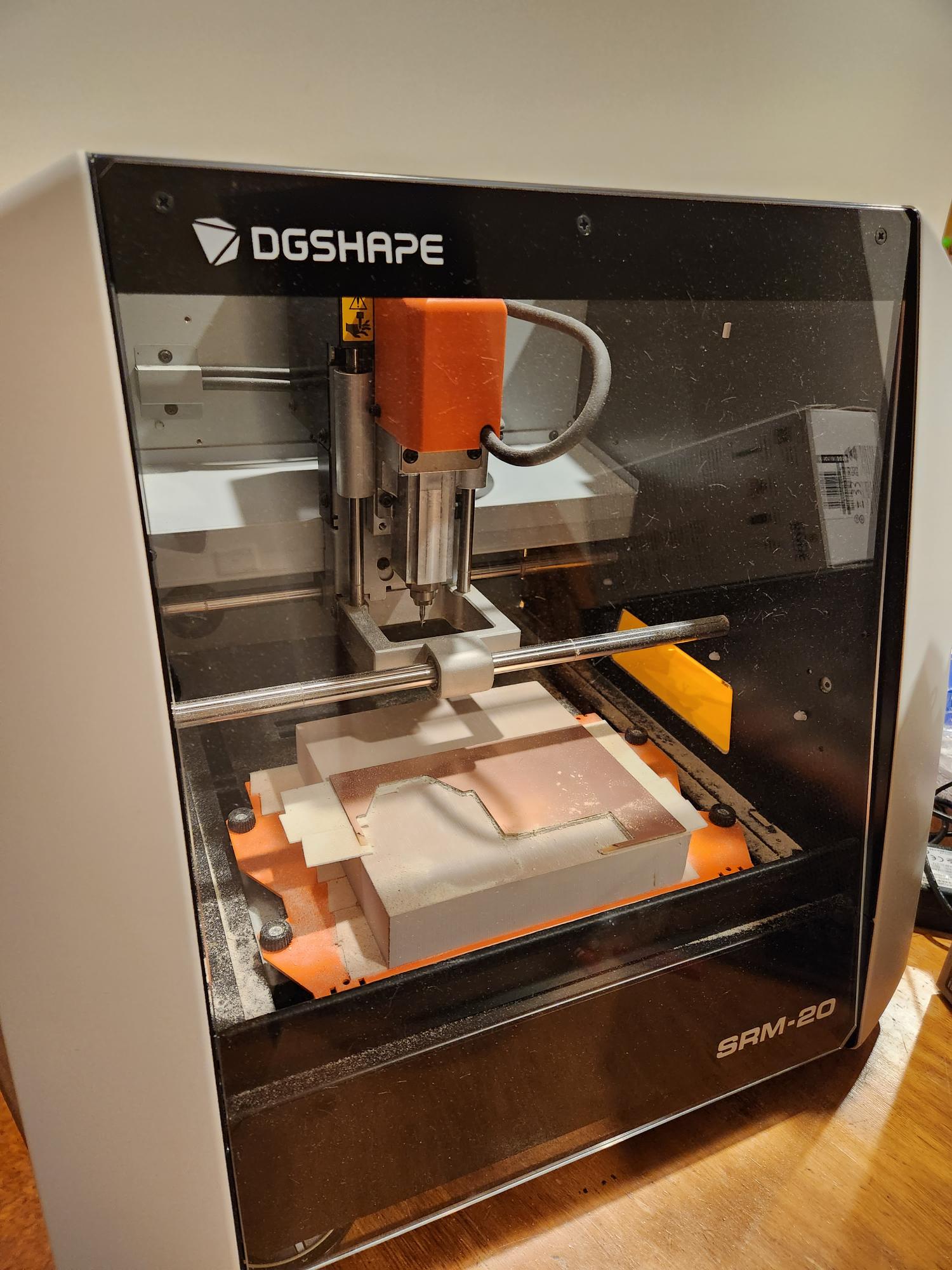
Machine and Specifications
Workpiece area: 232 x 156mm
Software Resolution: 0.01 mm/step (RML-1), 0.001mm/step (NC code)
Power Consumption: 50W
Acoustic Noise Level: 45-65dB
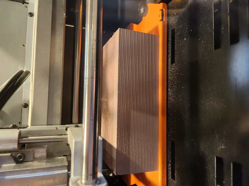
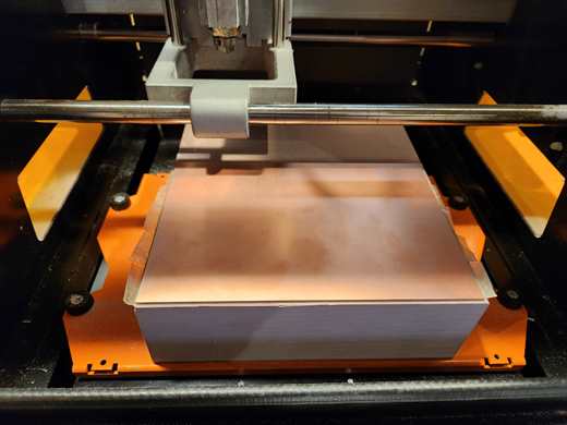
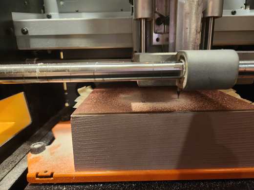
Milling the block / Leveling the machine
To ensure that your machine is level: you should mill a new block inside of the machine. This way the new surface will be level in relation to the machine drill bit, despite the table for example being crooked.
We followed the the documentation by 2022 Kamakura Fab Academy Students to do this https://fabacademy.org/2022/labs/kamakura/assignments/week04-kuriyama.html#surfacing
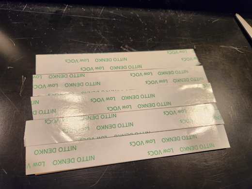
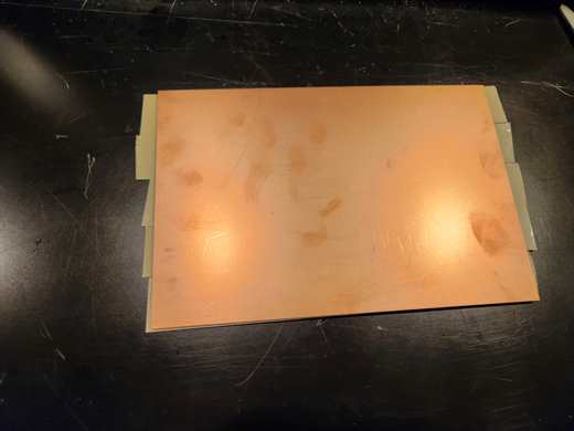
PCB Material Setup
Apply double sided tape to the PCB material (we used Copper-clad laminated substrate (cut substrate) (paper phenol single-sided / 100 x 150 x 1.6t) (No.12) by Sunhayato)
Make sure the tape covers the board, you want to make sure it sticks down level.
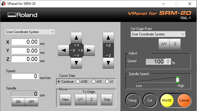
Machine Setup for Milling
When the machine is on open the Vpanel for SRM-20 on the connected computer.
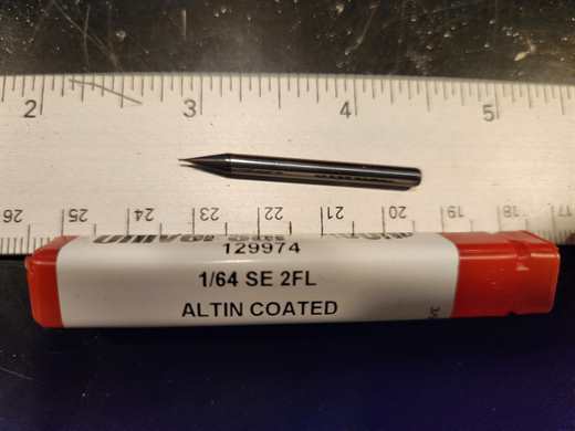
Insert the milling bit you are going to use, make sure not to over tighten the holding nut with the allen key.
For milling PCB traces use a 1/64 size bit
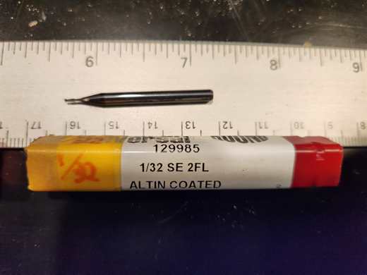
For cutting and holes use a 1/32 size bit
Use the arrow buttons on Vpanel to move the bit over where you want to set your origin. Note for z, get close to the board and then manually undo and place the bit on the surface.
To set the origin click the ‘Set Origin Point’ buttons for X/Y and Z found on the right side.
When ready to run click ‘Cut’ and select the file you want to cut.
Characterizing Design Rules
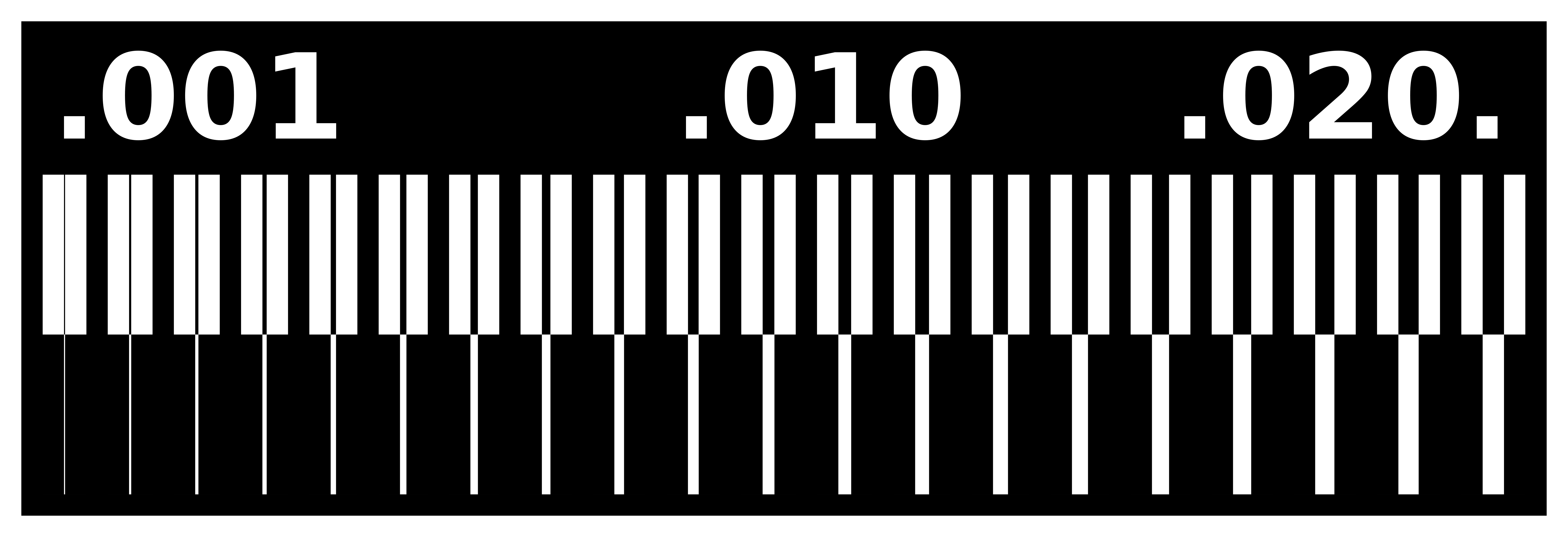
To define the design rules we, like previous years used Neil’s characterization file.
We use this to understand how thin we can make the lines, and the pathways surrounding the lines before they start peeling off.

Milling Files
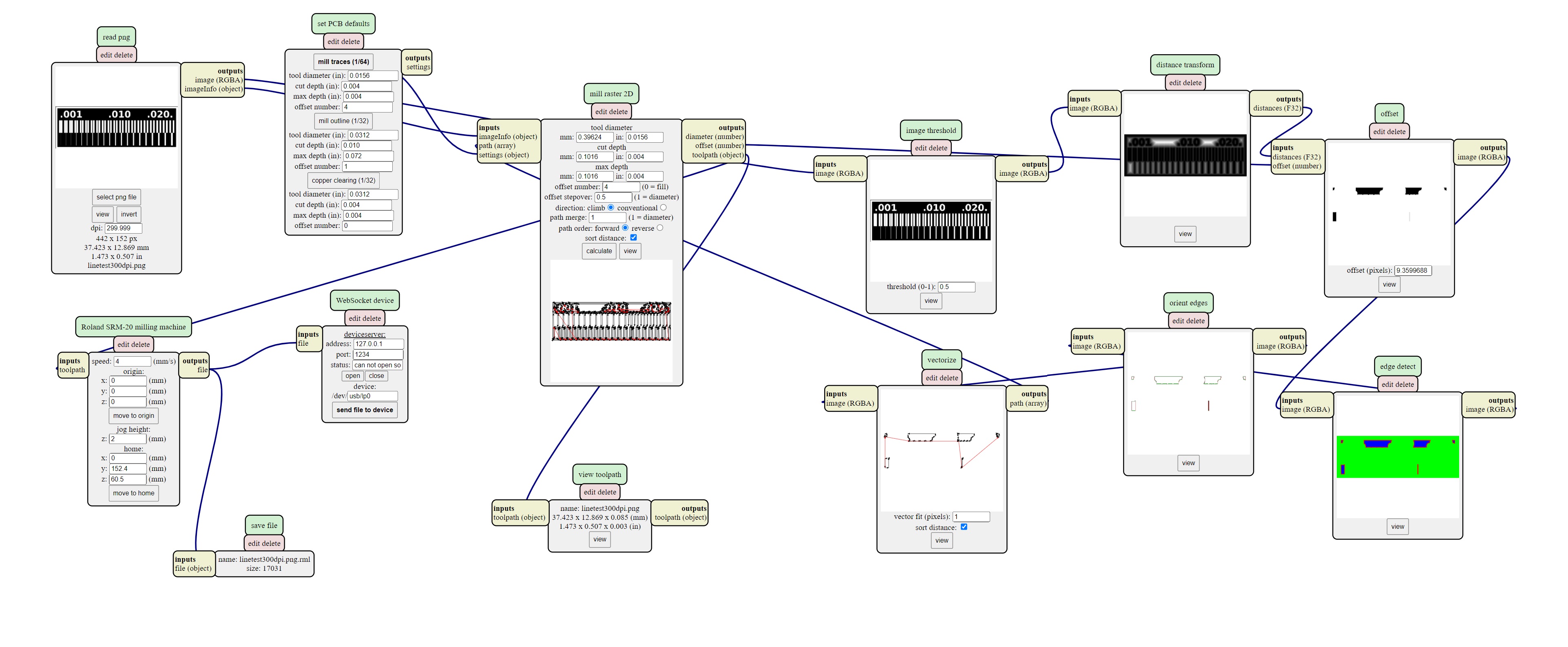
Use Mods to make the cut files for the SRM-20.
In Mods right click -> Programs -> Open Server Program -> SRM-20 -> PCB png
Also add a save file right click -> Modules -> Open Server Modules -> file -> save
And connect it to “outputs file”
Also change the top x, y and z in the Roland SRM-20 milling machine to 0.
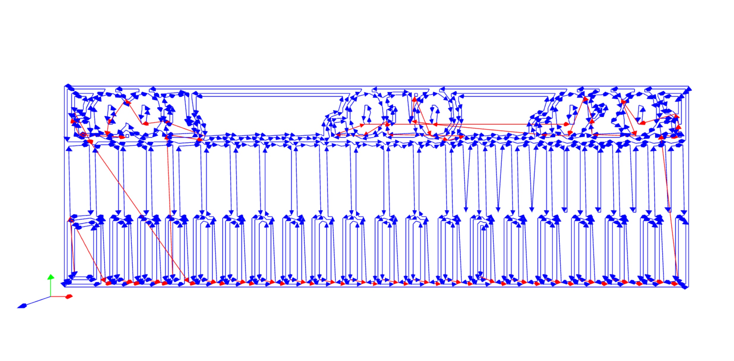
For the traces use “mill trace (1/64)”
For the edge and holes use “mill outline (1/32)”
Result
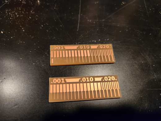
On our first run the outcome was not good (top). This is when we discovered that the block needed leveling. We also noted that Mods is affected by the resolution of the png you give it, so when saving the png file type save at 1000ppi/dpi.
On our second run (bottom) we got a good result. The limitation of milling width was 0.016 inches. Although we could get down to leaving 0.001 inches of copper, it did peel, so limit should really be 0.005 inches wide or 0.127mm.
This shows that using a minimum of 0.4mm wide for traces and 0.5mm gap between traces during design will work on our machine and milling bits.
Files
linetest.png
linetest.interior.png
linetest.png.rml
linetest.interior.png.rml