WEEK07 - COMPUTER CONTROLLED MACHINING
This week was dedicated computer controlled machining. We visited the FabLab at the Minatomirai Campus of Kanagawa University, to use their Shopbot for this assignment.
https://www.facebook.com/fablab.minatomirai/
We first went through the Labs safety protocols and did our group assignments and then embarked to cut and complete our individual assignments which we had already designed previously.
WEEK SEVEN ASSIGNMENT
- do your lab’s safety training
- test runout, alignment, fixturing, speeds, feeds, materials, and toolpaths for your machine
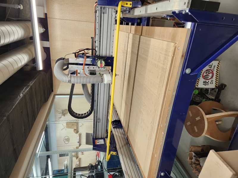
MACHINE SPECS:
At MinatomiRai the following CNC Machine is in use:
Since this is a university lab the safety rules and interactions with the machine are more strict than other fablabs, and we had to do a seperate safety lecture for the lab itself other than just for the CNC.
The overall safety rules are in-place: No open shoes No loose hair No loose clothing Be alert etc
Additionally the machine is set up with certain safety-measures in place which were tied to how the machine is set up: for example the wrench is linked directly to the key so it is physically impossible to attempt to change anything on the machine while the key is still plugged in.
SHOP BOT GROUP ASSIGNMENT
For this weeks group assignment we categorized the Shopbot machine. - Vcarve / Data - Inserting Drillbit - Adjusting X,Y - Adjusting Z - Adjusting the Material - Steps towards cutting + finishing
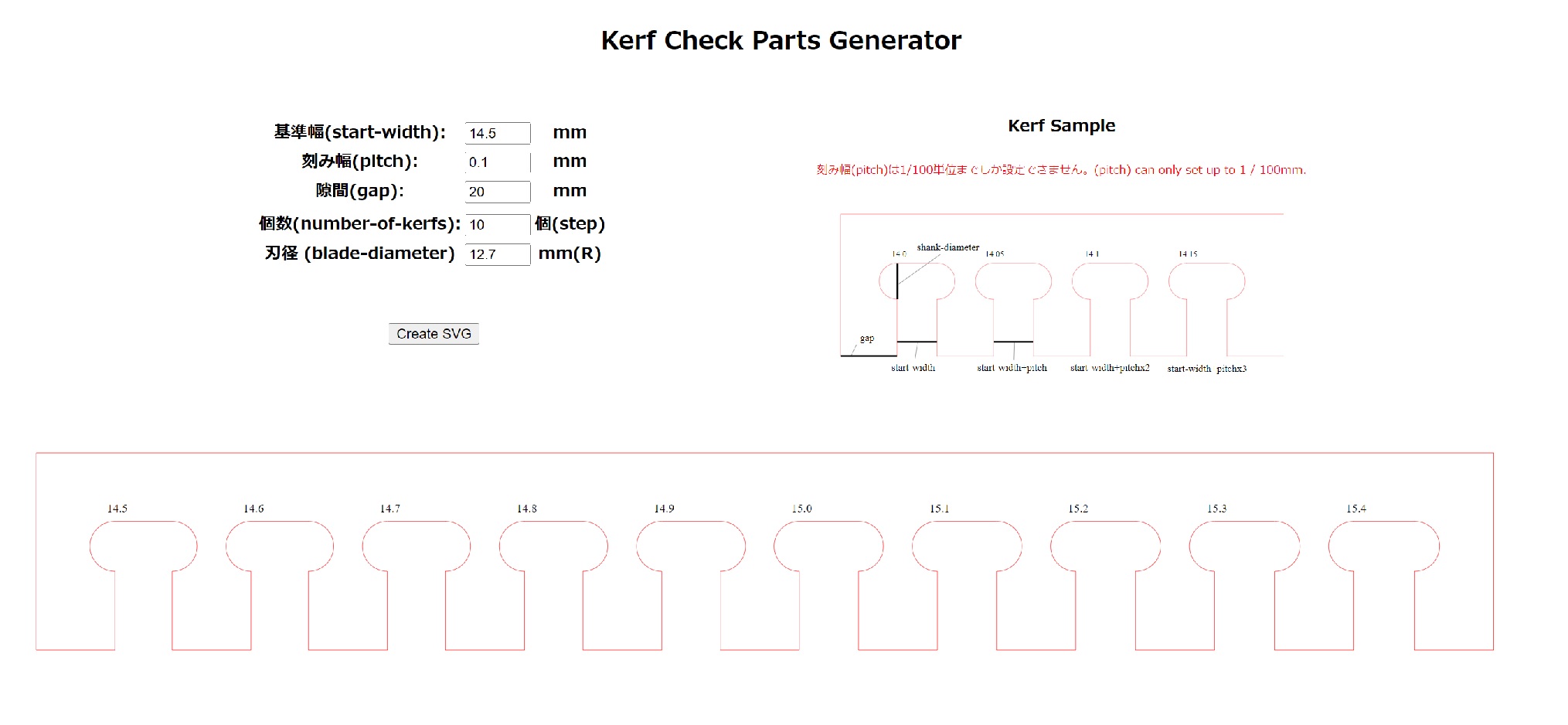
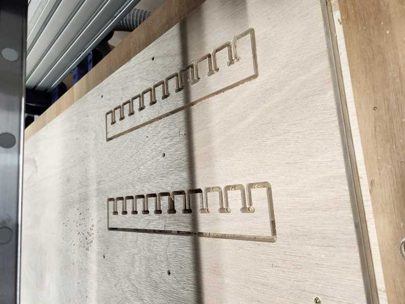
KERF TEST FILE
We generated the Kerf SVG test file for use with 15mm thick plywood using the Kerf Check Parts Generator

STEP BY STEP
0. Open VCarve and Import Vectors
1. Check Preview Mode
2. File -> Drill -> open.
3. Click start. -> it shows you to the cut-path (you can toggle between 3D or 2D view)
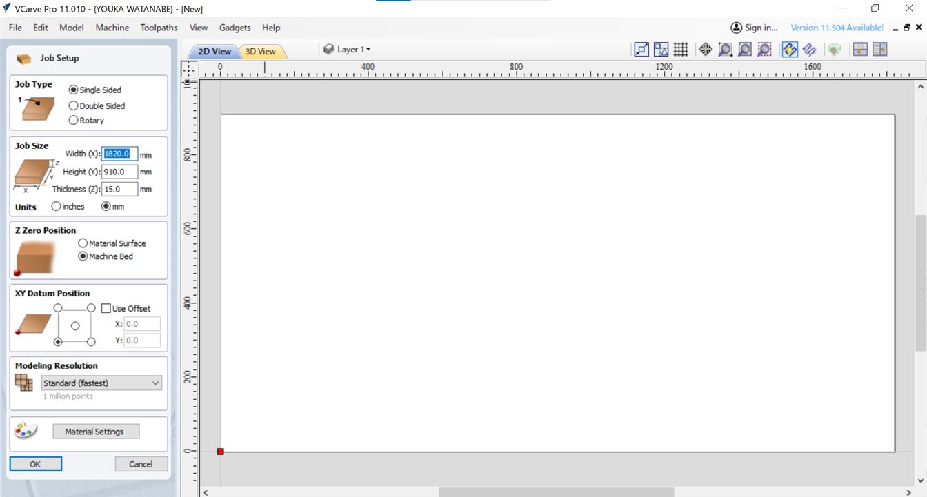
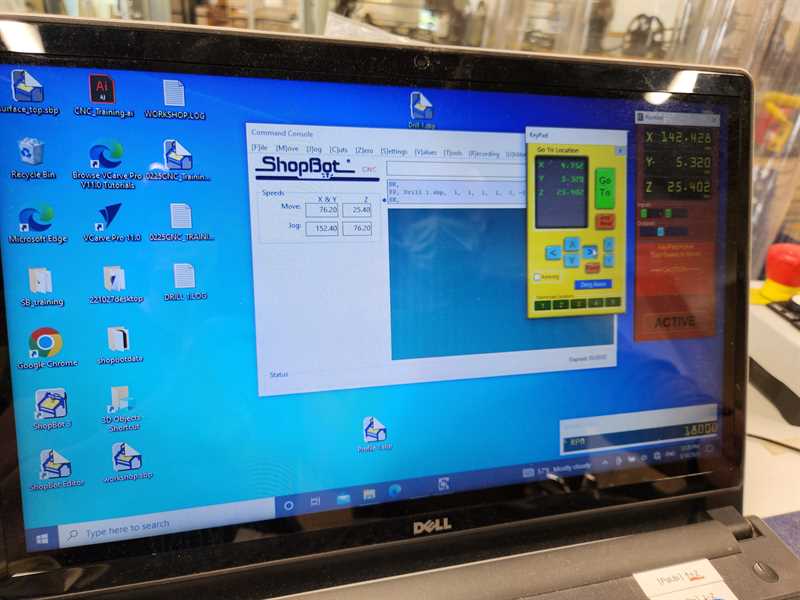
4. set X and Y to 0.0 & input wood/material parameters
[ you do this so that you can check that the g-code is correct. for this we have to give the machine context in the shape of the material that we are using]
-> change to the side-view to check the Z-path and whether it suits your needs ( not too deep or too shallow).
-> set the toolpath parameters
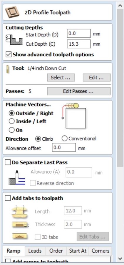
If everything is correct -> congrats you have checked your path data
NEXT
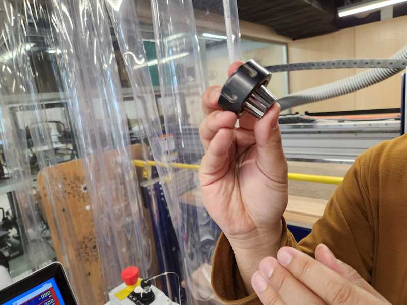
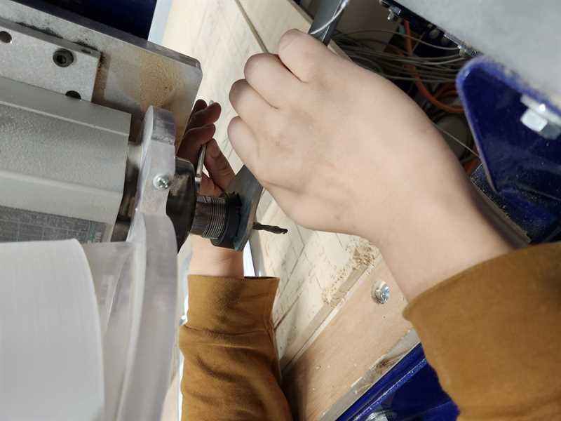
5. Insert Drill bit
5.1 -> insert drill bit ( assemble drill bit holder) SAFETY MECHANISIM: at the Minatomirai FabLab the wrench required to loosen and tighten the drill-bit is directly attached to the key to start the drill motion. This ensures that there is no way that you could reach to touch the drill bit without prior turning off the drill bit motion.
5.2 -> tighten drill-bit!!

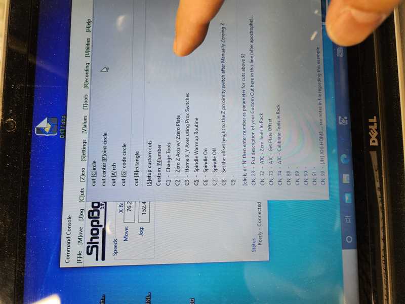
6. Adjust X + Y axis.
6.1 adjustable via desktop buttons
6.2 position for HOME: using C3 on computer.
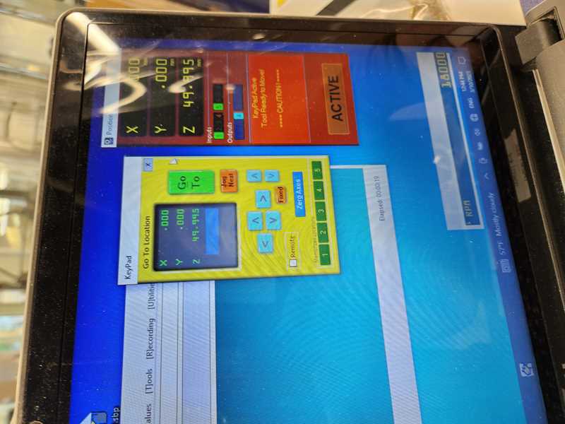
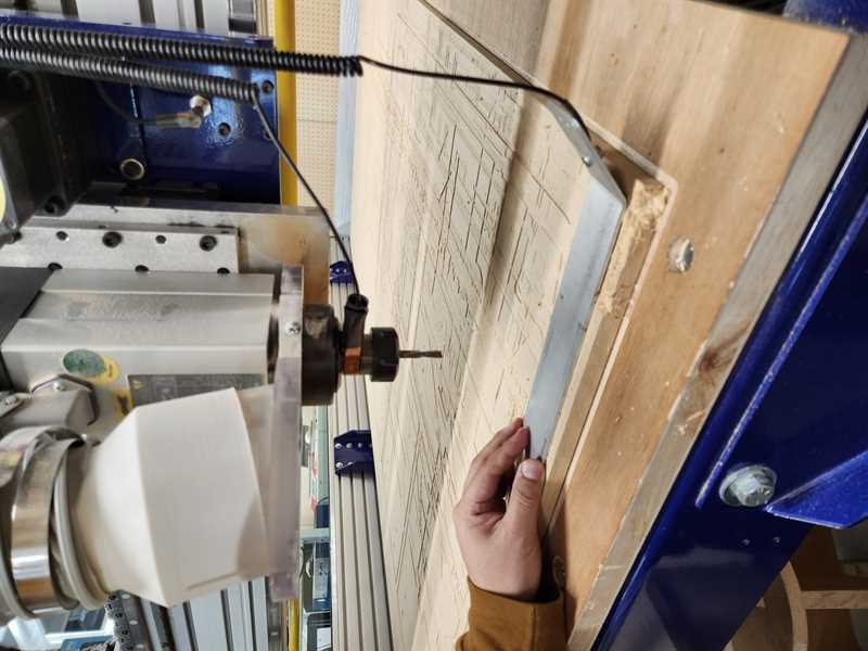
7. Set the Z axis ( assigning 0 point)
In this particular shop-bot we assign the 0 of the Z-axis to the machine bed level, not the material surface!!!
You do this using a metal flat probe and a closed circuit.
7.1 Place the metal plate on the machine bed
7.2 Attach voltage to the drill bit -> this way when the drill lowers and touches the plate the circuit completes and the machine knows that it has touched a surface and that this is now zero.
7.3 Press C2 -> the z axis will move towards it’s home position and touch the metal plate mutltiple times to ensure it has accurately measured the new 0 location.
7.4 -> you have now set the Z axis. Don’t forget to remove the alligator clip and put away the plate.

8. Setting the Material
8.1 move the x,y axis out of the way so that you can insert the material
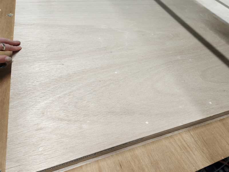
8.2 place material on the board
8.3 ensure that the material is postioned in the 0/0 point of the x,y axis ( the front right-wing corner at this particular shopbot)
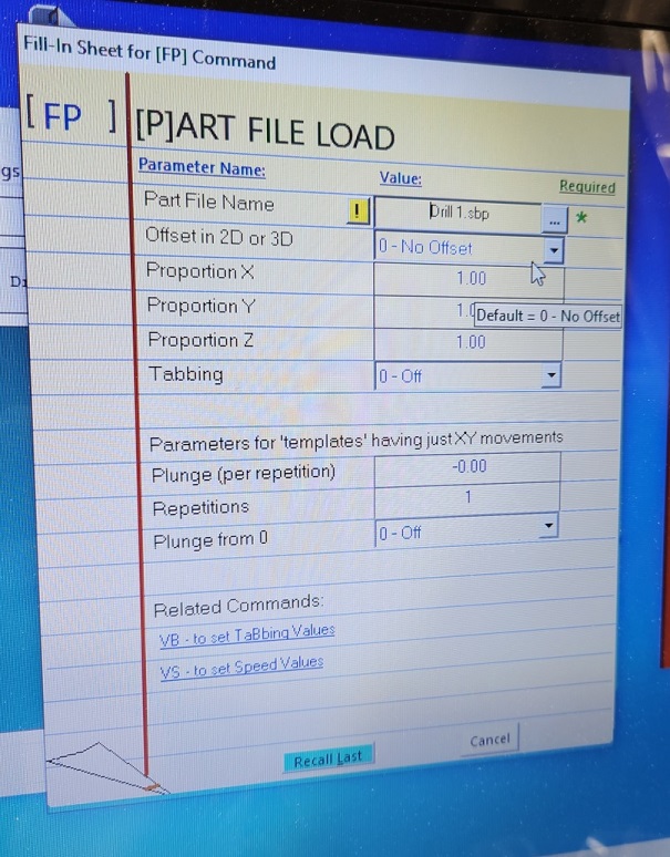
8.4 Load the drill file ( the file that shows the drillholes for where your material will be drilled to the machine bed)
8.5 do an AIRPASS of your drill file to make sure everything seems correct.
8.4 load the drill data again -> this time without the off-set.
8.5 press start and answer all of the question the machine throws at you.
8.6 drill the holes
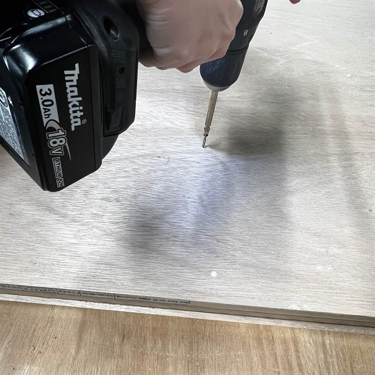
8.7 after the machine is done, screw nails/ screws into the holes that were made to fix your material to the machine bed.
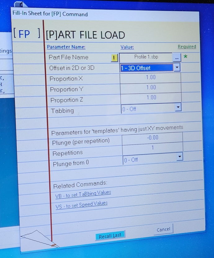
9. Cutting the material
9.1 ALWAYS DO AN AIRPASS. ( so load the file -> 3D offset the Z axis to cut in the air)
9.2 attach the extraction attachment
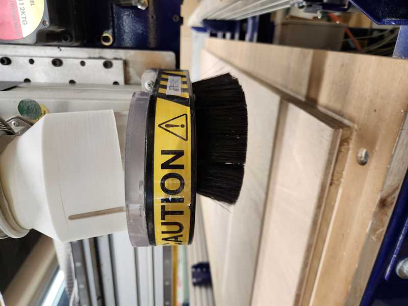
9.3 turn on the absorption
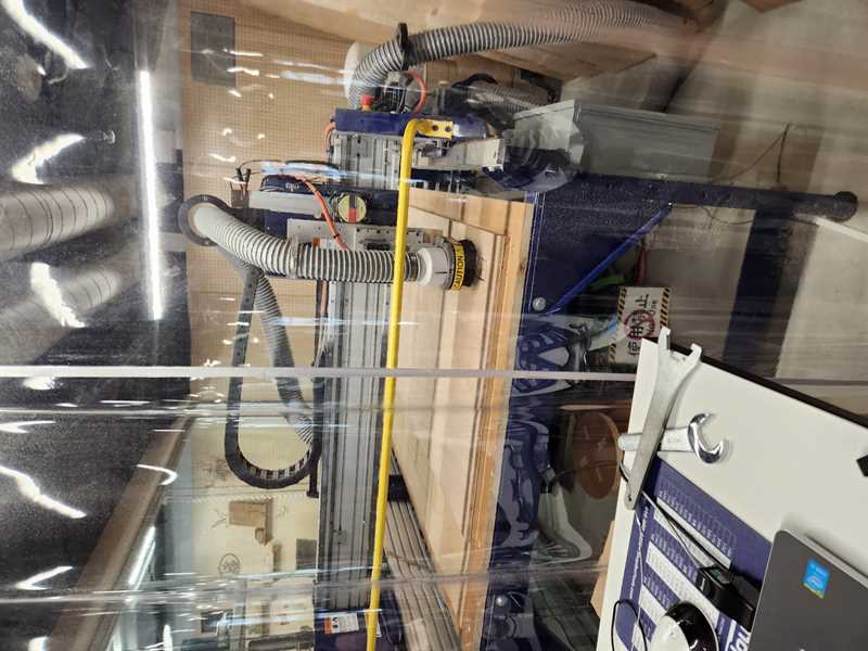
9.4 close the curtain
9.5 load file -> do airpass / make sure the drill spots are not in the cut path
9.6 load file -> press start -> cut.
9.7 once done, unload the material etc.
Result
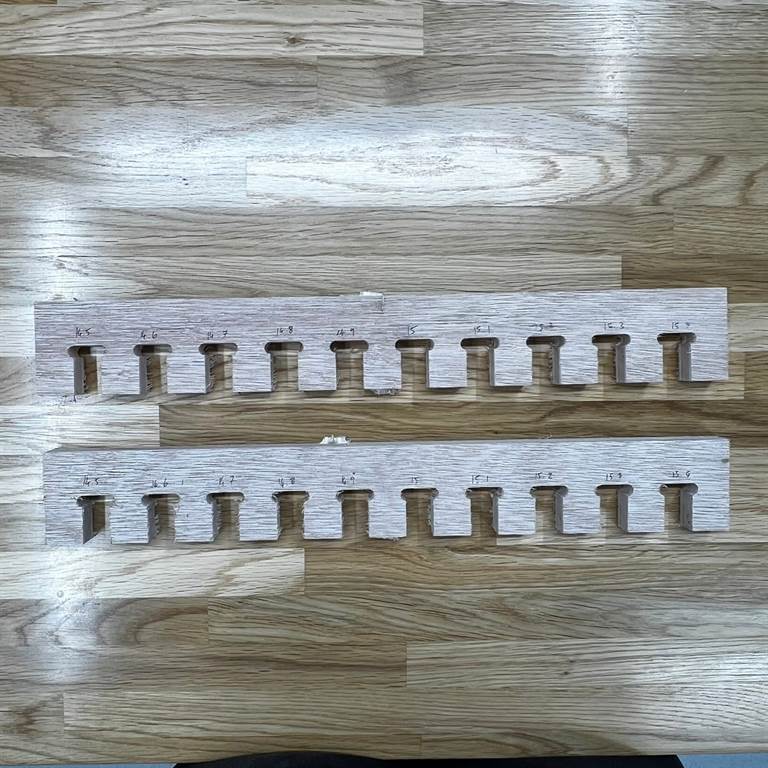
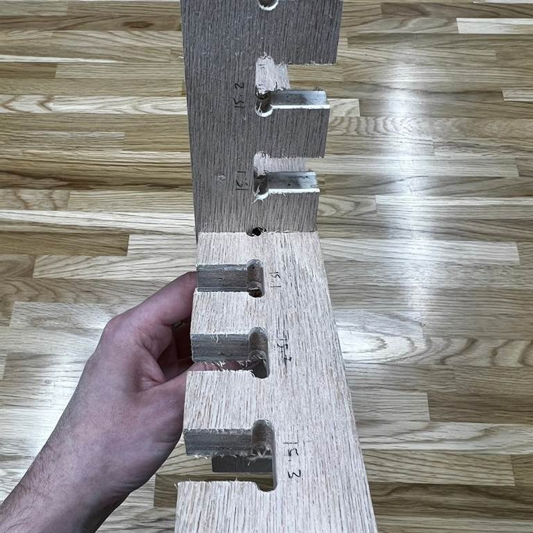
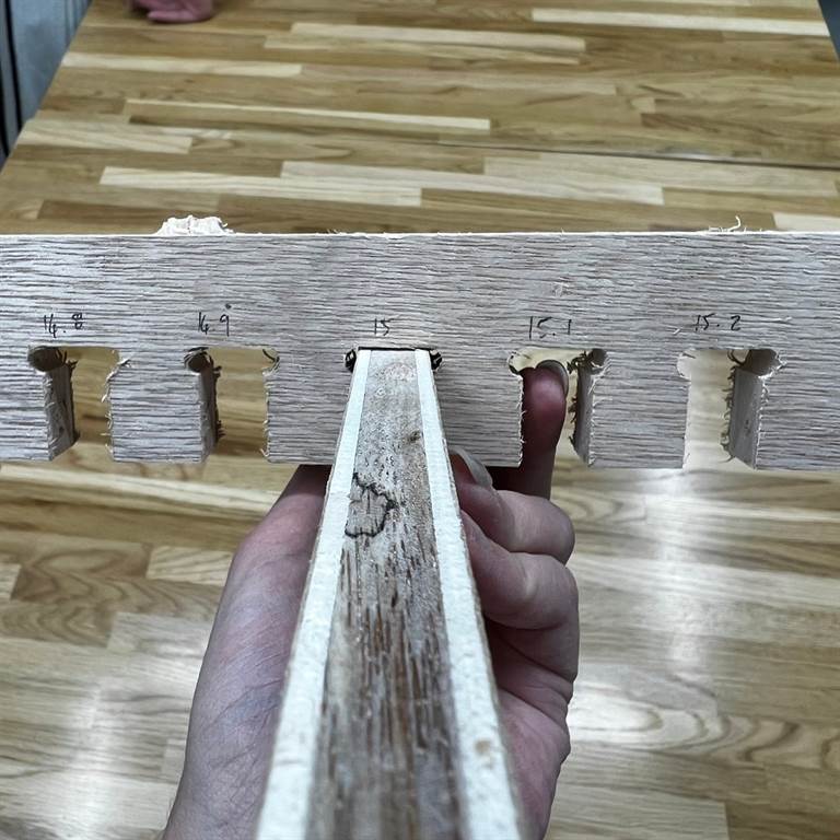
We found that 15 fit well together.