Week 9
Mar 22: Output devices
List of task this week
Group assignment
To see the group assignment go here.
My thoughts on this week’s group assignment, Measure the power consumption of an output device: It was mostly how I expected it to be but it was interesting to see how the amps were calculated.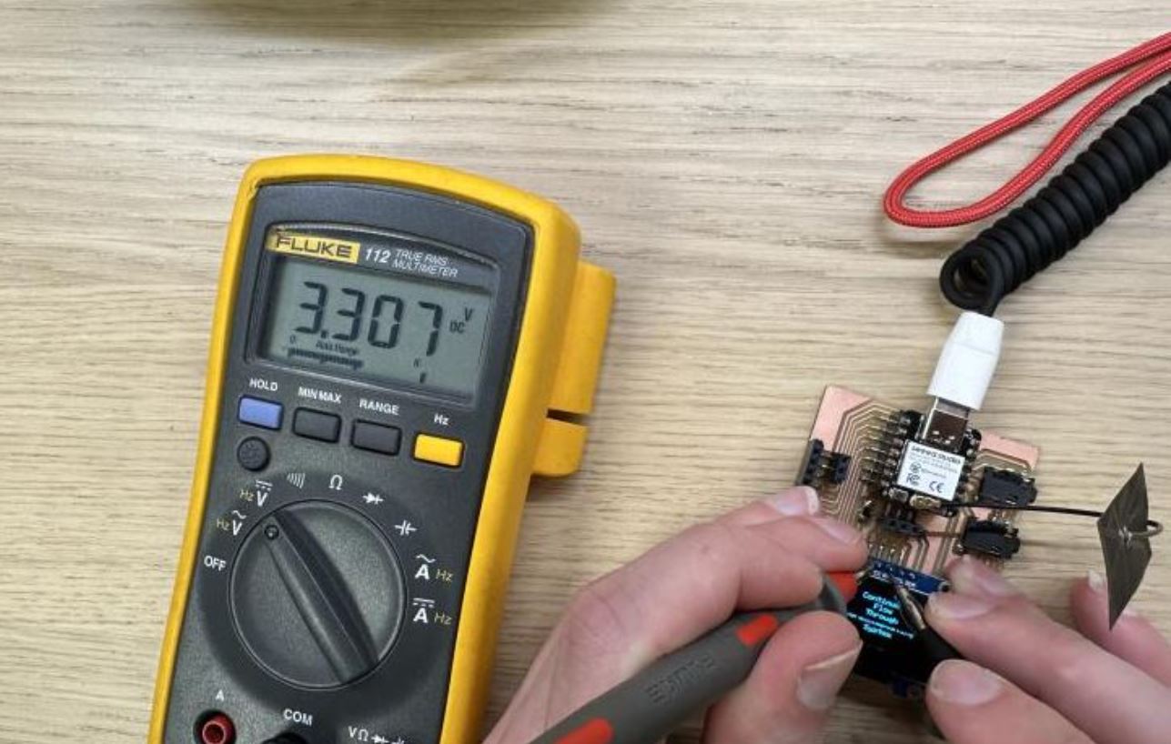
Add an output device to a microcontroller board you've designed, and program it to do something
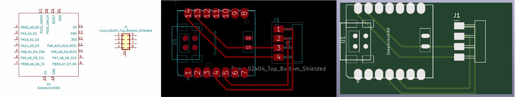
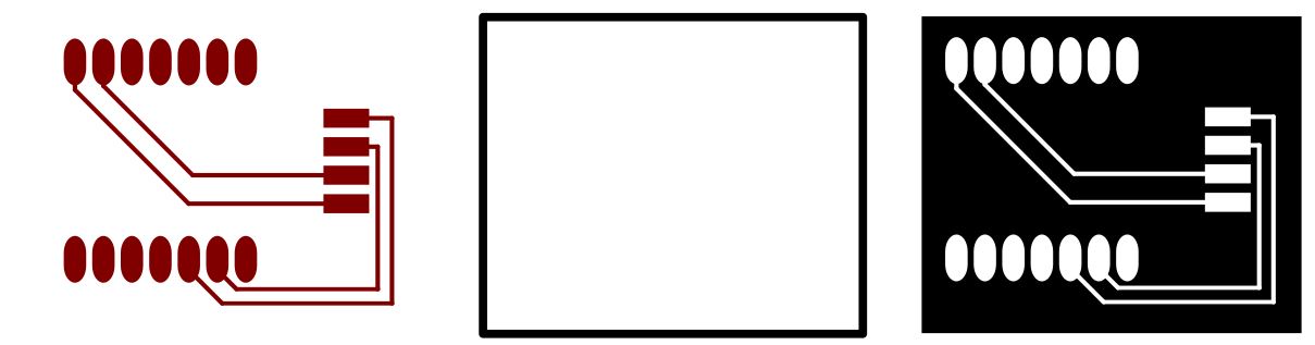
To see how to make a board in Kicad go here. The board I made only had two components, A esp32-c3 XIAO and an Oled screen. The Oled screen only needs four pins, power, GND, SCL and SDA which on the XIAO are pin 4 and 5. See datasheet here. I made this simple board in Kicad and exported it to svg.
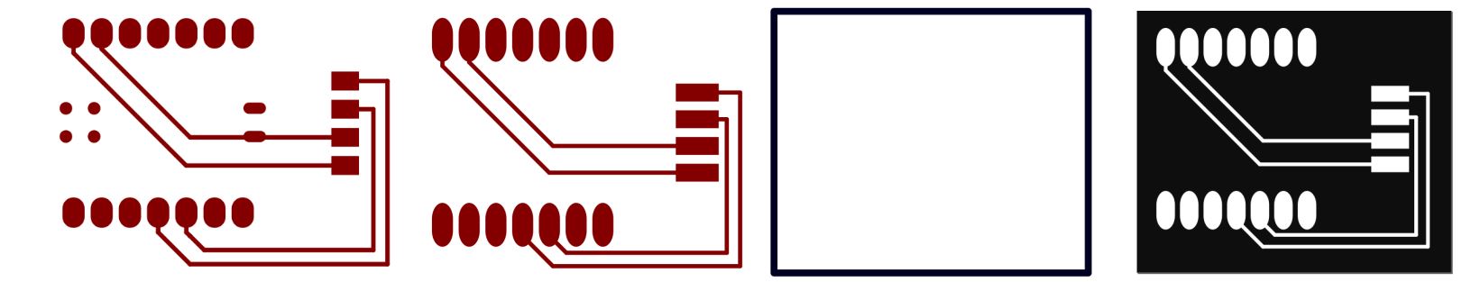
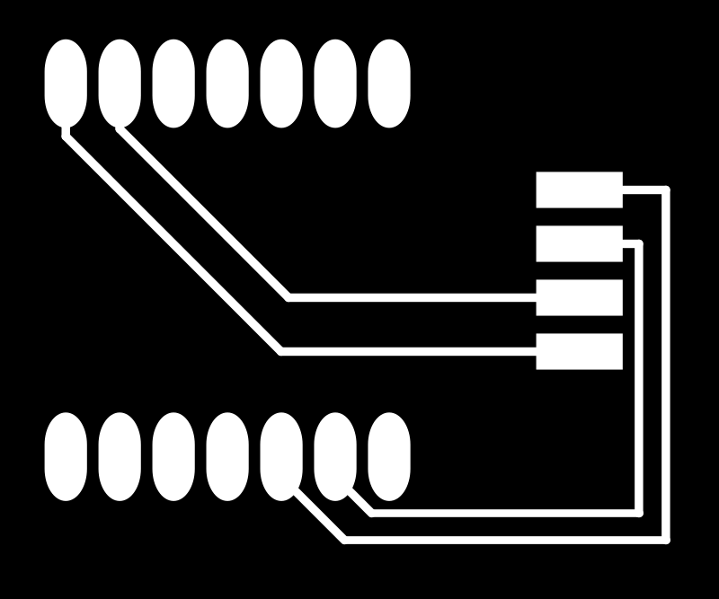
Because I was going to have the XIAO on feet I extended the blobs so it would be easier to solder, I did the same for the feet of the Oled This can all be easily done in Inkscape, just have in mind that if when you are making it bigger on one side and it pulls all sides it is possibly stroke and we want it to be a path, so just select it, go to path and click stroke to path. I deleted the spots on the bottom of the XIAO since there was no need for them. I inverted the paths and made a frame to cut.
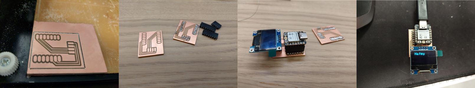
I milled out the files. To see how I mill out see the group page week 8. I was really confused that
it did not work, I tried so many different codes and nothing and then I notice something… I had the
wrong pins connected. It starts with pin 0 and I counted like it started on pin 1. I tested my theory and
connected wires to see if I was right, with the right pins everything went smoothly. I got the code from
this site and just changed it a little.
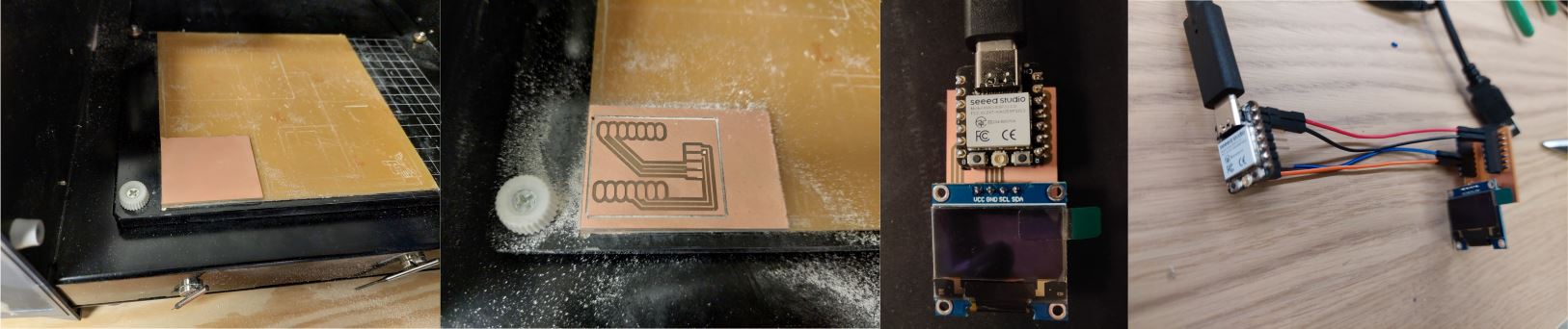
I milled a second board, took the feet of the old one and soldered them on the new one, this time everything worked perfectly, I put my name in the code to see how that would be.
I spent so much time trying to get the board from week 8 to work that I had to make something simple to try to catch up.