Fab Academy
Arthur DEFRAIN

Final Project

Pharos
The Meeting Status

How to be sure no one will disturbe you during your meeting.

​Meeting status

​The problem

​Since Covid-19 and the resulting remote work, everyone is meeting online on different platforms. But no matter what you're doing, your university, your family, or someone else will disturb you during a meeting, or you will disturb someone. Because it's very hard now to tell if you're in a meeting or just working with music in your headphones.

The Goal

The goal is to solve the ignoring status of someone at home or at the office without interfering with him.
The same way that few app show if your are online or offline, and somtime with more details.

Inspiration

the idea is to plug trought USB or remotly connected and indicate if your are in a call / busy / free ...

​A status light already exists in the industry to visually indicate the state of the device. In this way, the operator can see the status even from a distance.

The Need

​This product is going to help us a lot, we don't have individual desks, everyone has different projects or tedious tasks to do. The way to have directions for others is a way to stay focused and productive when needed. The idea is to make one for each employee, that way our status can be known by everyone.

​How I did it

​Step #1: Scketch

​The idea behind the project is to use an object in an office to indicate its availability.

​I have several choices on how to present this information

​Directly on the desk, but it takes up space

​On screen, like a webcam, practical for open spaces.

​Fix to a wall like a lantern, practical for closed offices.

​In any case, this lantern will be controlled by a mini keypad. This box will control the lantern and also visually indicate the status, or at least the color displayed. I'm going with 3 colors, because that's pretty much what I need, but more color options can be thought of (colorblindness, 4 colors...).

Step #2: Prototype design 

​The device is completely folded which gives it the possibility to stand without being on a screen 

​The devices put in situation on a screen 

Find how i make those render with Fusion 360 

​Once I've designed it, I 3D print the various parts 
The housing in FDM printing and the pole in resin, resin was used so that the light can diffuse through it . I could also do it in a mold and resin

​Impression files

Control box

Pole

Case Closing Keycap Inside part Pole Lantern

The keycap come from Grabcad

Step #3: Design the PCB​

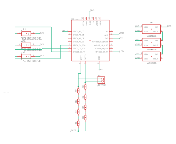
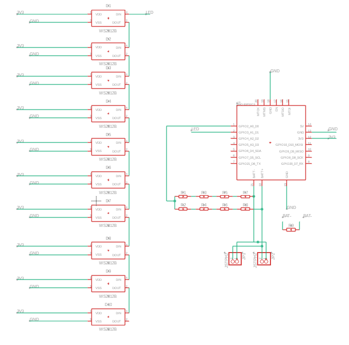
​Before we can make the printed circuit boards, we need to know what does what in our board. In this first circuit, the control part, we have:
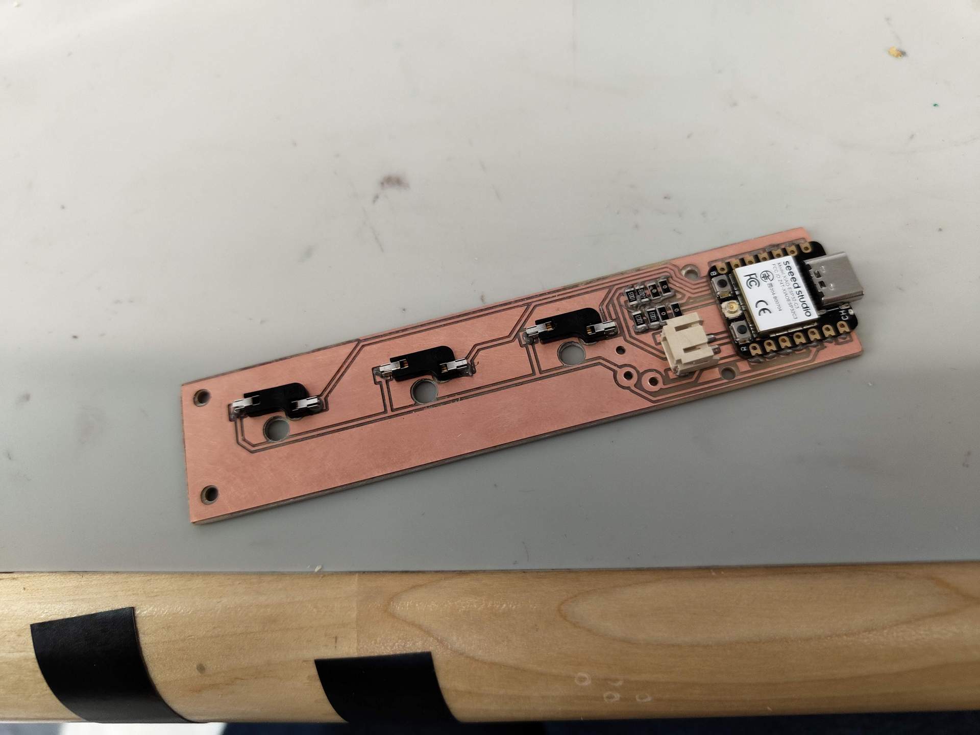
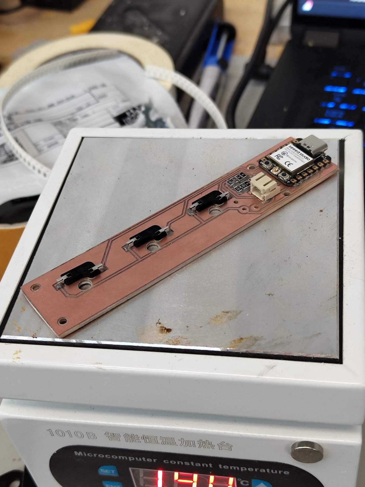
- 1 Seeed Studio Xiao ESP32-C3
- 3 LED Neopixel WS2812B- 3 Hot-swap socket for keyboard button 
- 1 connector JST 2 pin
- some resistor 
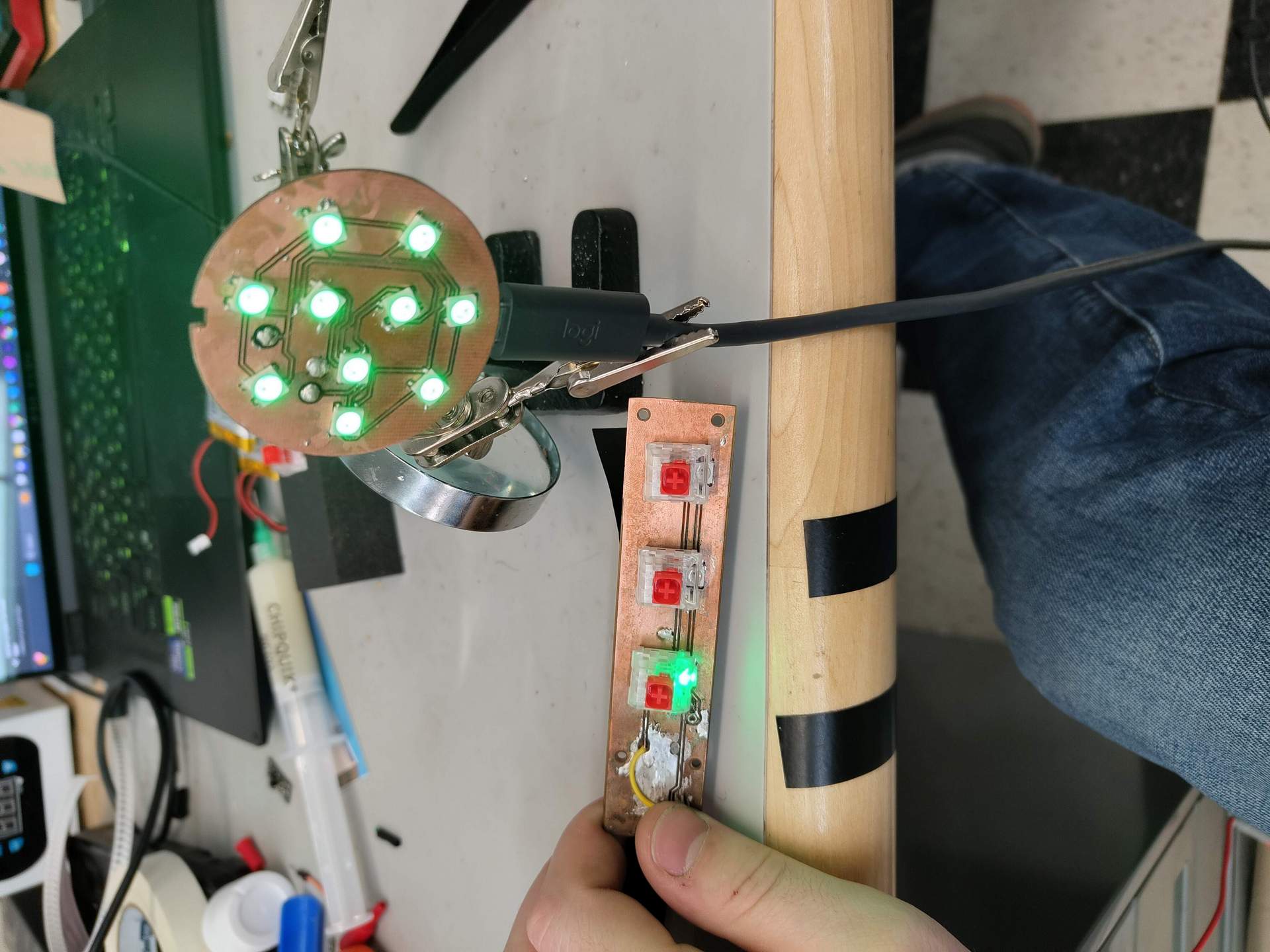
On this circuit we'll have an LED under each button, to give feedback on the status We also have a resistor between the battery (connect to connector JST 2) and a terminal of the Xiao to read the voltage on the battery.communication via WIFI is done directly on the Xiao.

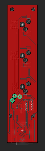
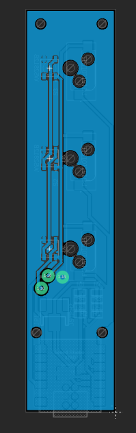
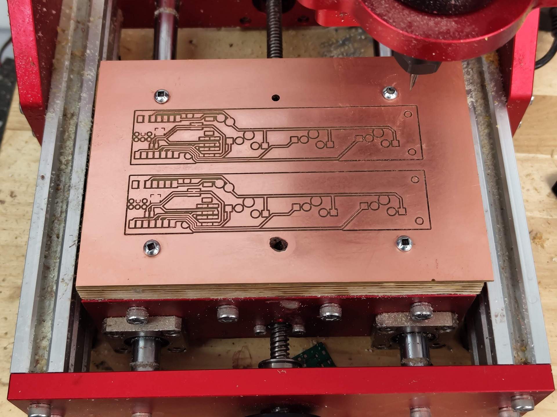
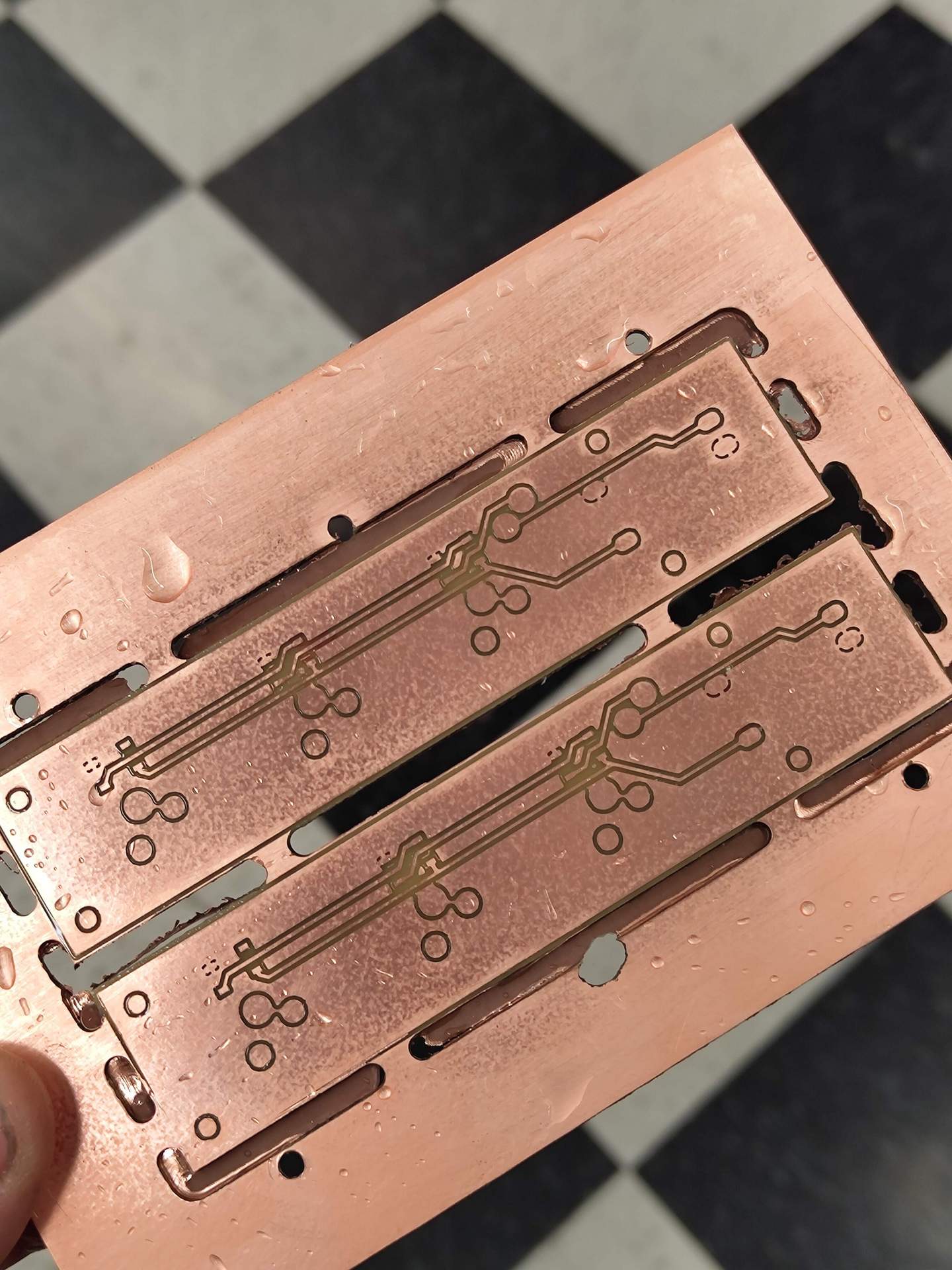
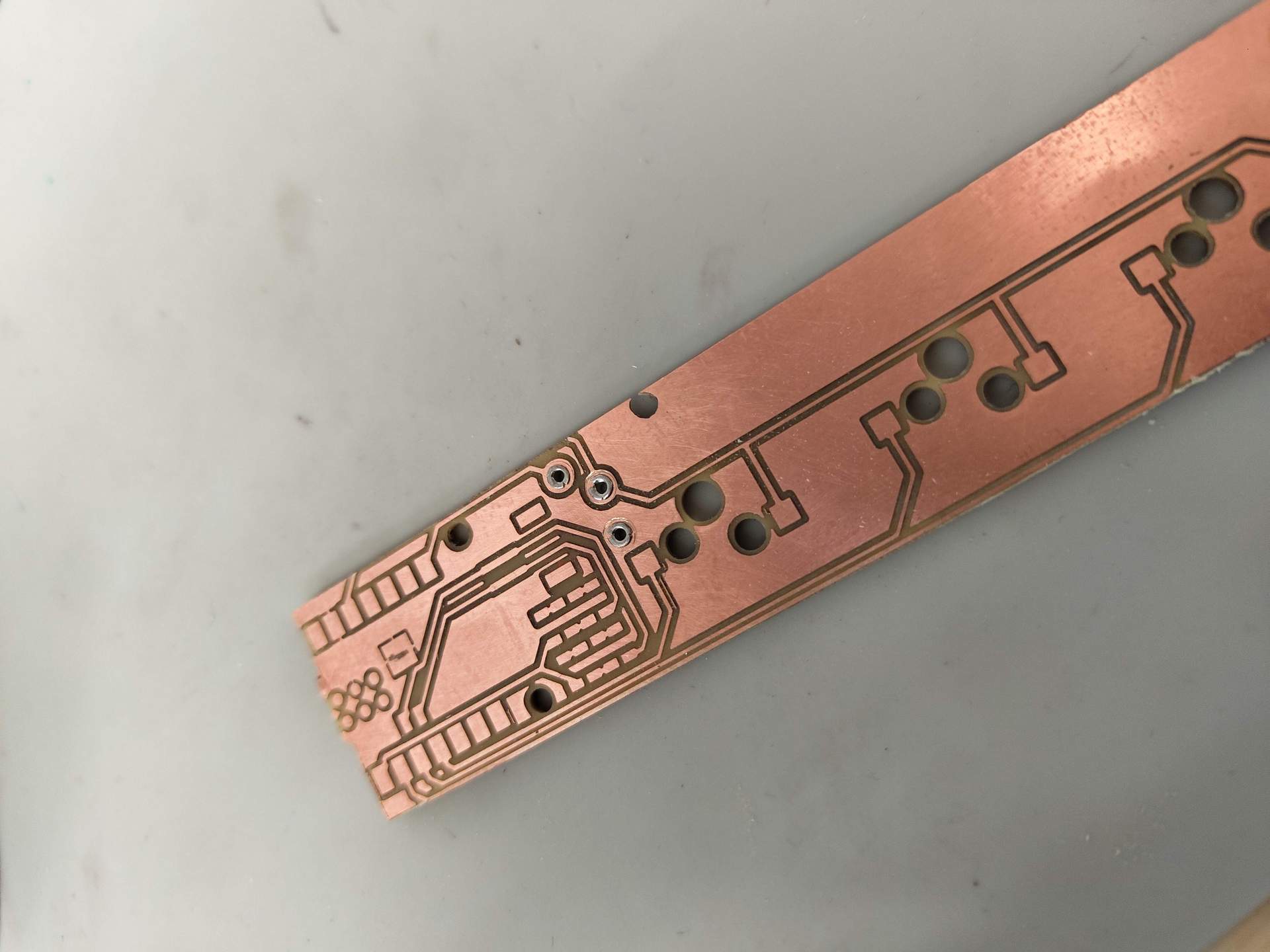
​Once I've taken the shape and dimensions of the case, I can make the PCB. I place all the elements, taking particular care that the LEDs are well below the future buttons without generating them. Once in place, I can draw and/or connect the different elements together.
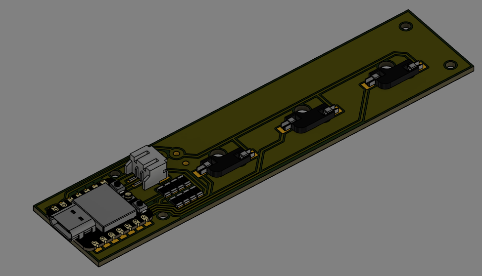
Side 2

Side 1​

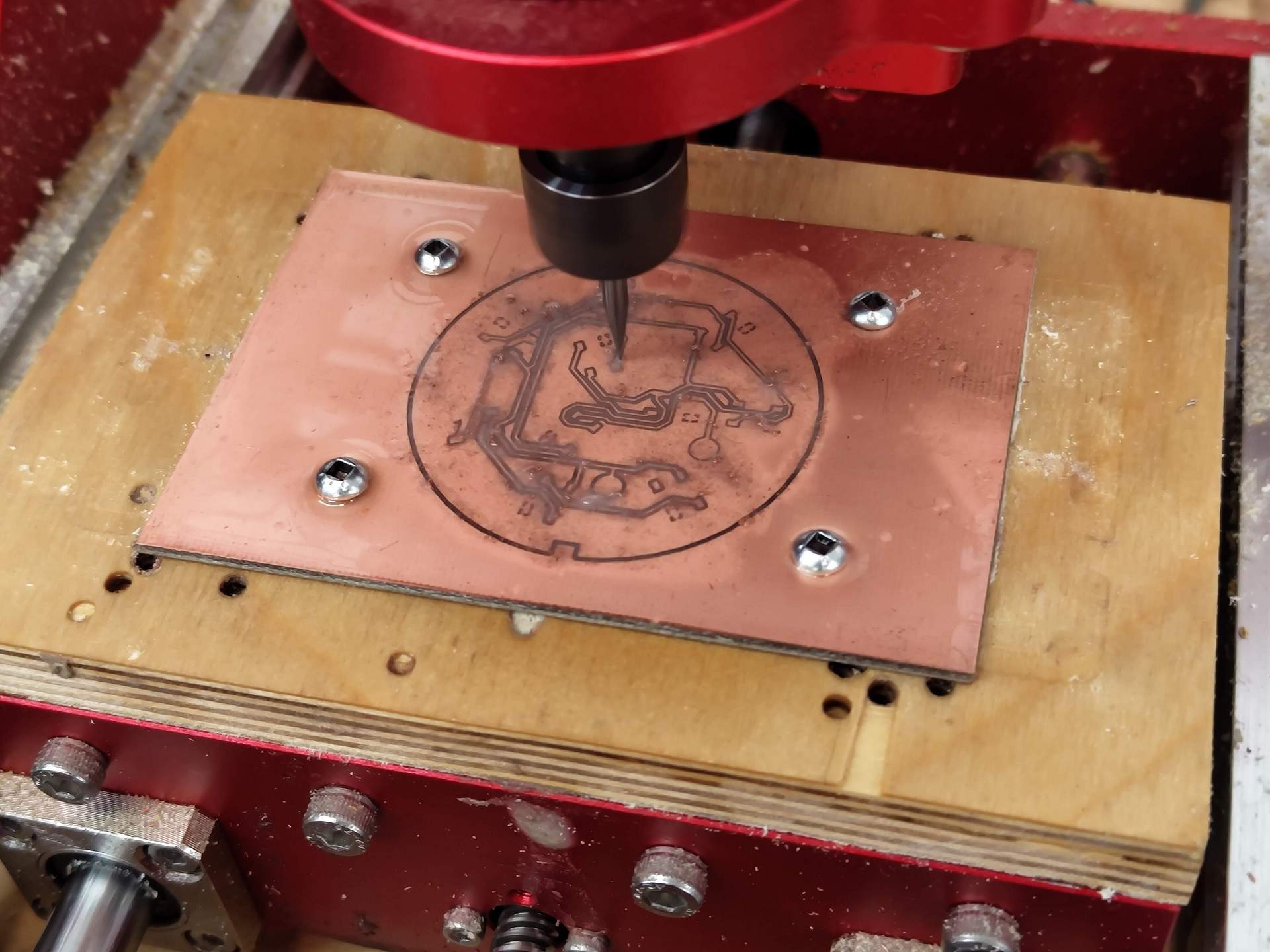
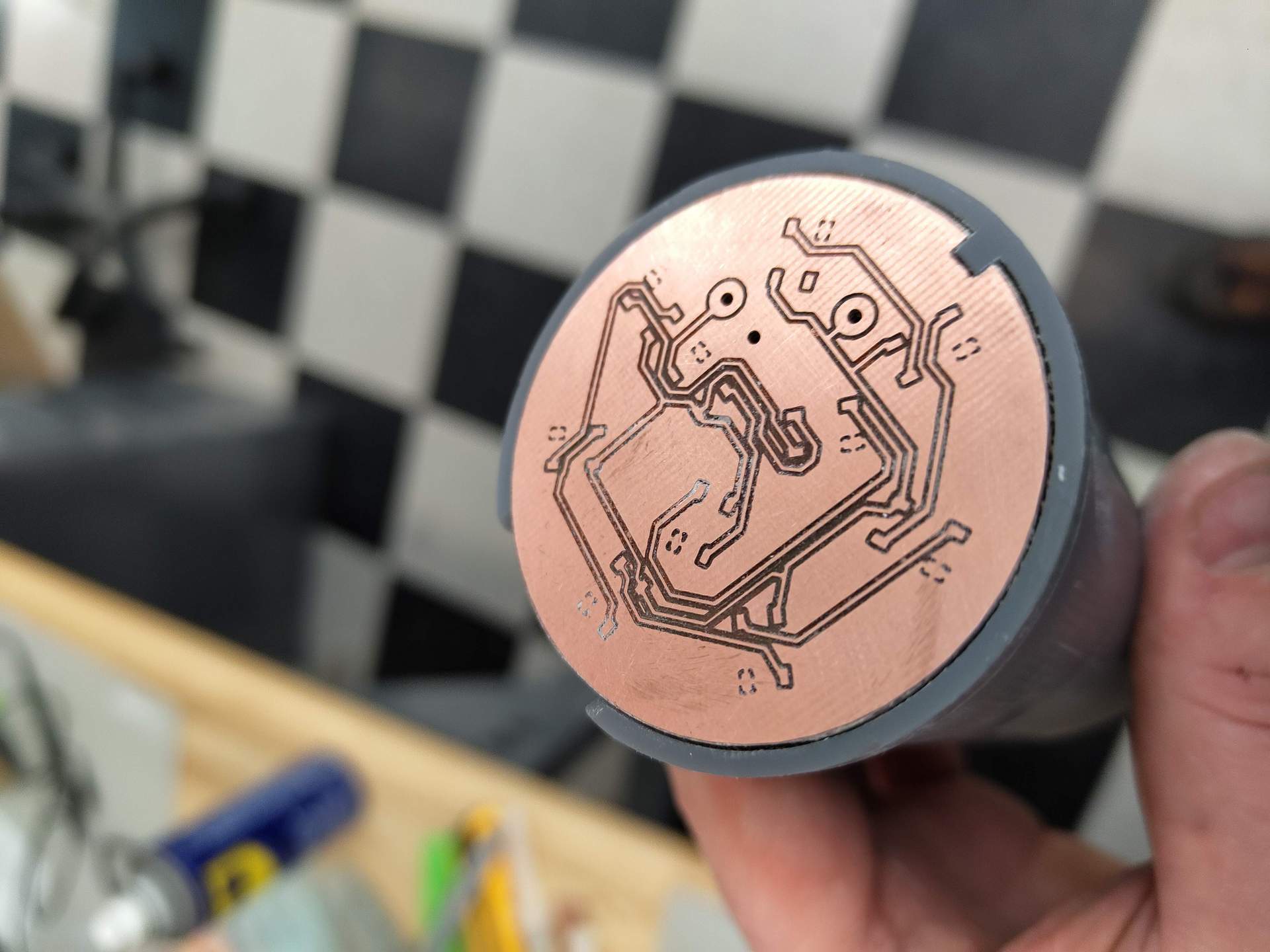
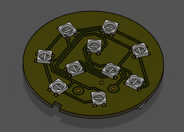
​On the second circuit, the one that will give the information to other people, is simpler. There are more LEDs (10) but no buttons. There are also 2 JST 2 ports for 2 batteries. This will give greater autonomy, as the 10 LEDs will continuously emit the color requested by the controller. And at maximum power, so that everyone can see the color.
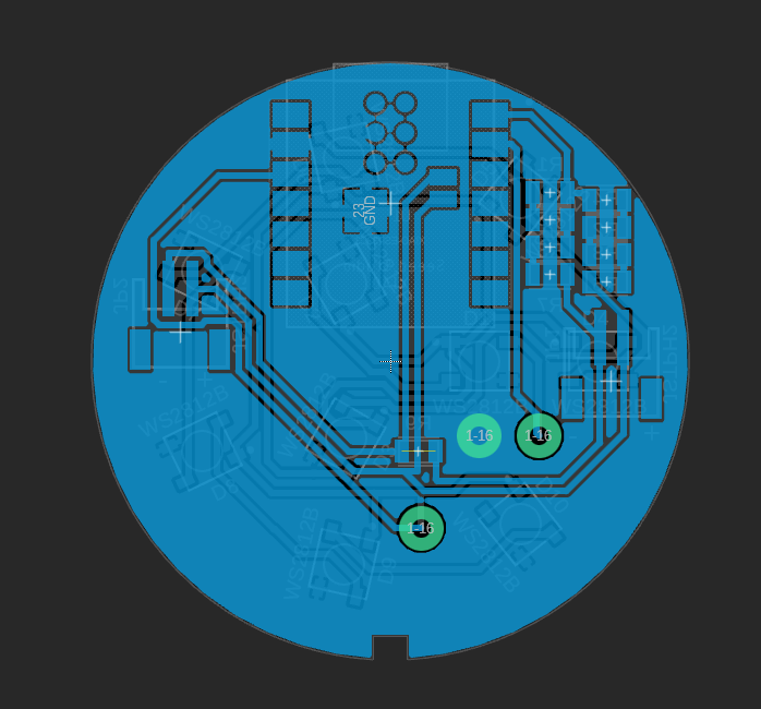
Side 2

Side 1

​I also take the shape to place the elements, place everything and connect them. The result is a round circuit with the LEDs on one side and the Xiao and connectors on the other.

​Here are the files

Controle PCB Pole PCB

​Step #4: Making the circuit board

​To make these two cricuit I do as in week 4, ​but this time they're double-sided, i.e. I have tracks to make on both sides of the PCB. To do this, I've added a step that creates pawns to ensure that when I turn the plate over, it's aligned.

​Once the tracks have been made on both sides, I can now separate the PCBs and make the second PCB.

​After I've made this second PCB, I can test whether the whole thing fits together within the 3D-printed parts.

​To have continuity between the two sides, and to pass signals between the two sides, I need "vias". These are conductive pieces that I hammer to make contact with each side of the PCB. I could also use a bit of solder, but that's less clean.

​Once done, I can solder the elements to the circuits.

​File for Flat Cam

Control PCB Pole PCB

​Step #5: Code and test

​Code Controleur Code Pole

​To code the two Xiao ESP32-C3 I'm using Chat GPT because I'm not very good at it. 
I test each step on the two Xiao's. 

I test the LED's. I test the communication. 

I test the button reading. 

I associate the buttons with their LED's. 

I control the LED's from the controller. 

I optimize the code and make it faster and more reactive.

Result ​