4. embedded programming
Assignments
individual assignment:
- browse through the data sheet for your microcontroller
- program a microcontroller development board
- to interact (with local input &/or output) and communicate (remotely)
- extra credit: use different languages &/or development environments
group assignment:
- compare the performance and development workflows for other architectures
Research
Files
here is the download link for all of my code files for this week
Zip File Download
Throughout The Week
This week I re-learned and learned how to use and code many microcontrollers. I relearned the basics of Arduino and how to use it with an ATTiny412 chip. I also learned how to do bare metal or C, on the ATTiny. Next o learned how to use a raspberry pico on both Arduino and thonny/python.
group work
For the group work this week we were assigned a microcontoller and we had to compare it to the other groups at our school. Here is the group link.
Arduino
Before I began working with Arduino I already had used them both before so I felt confident moving forward without using a tutorial. I started with the Arduino and just made a LED blink with the code seen below
void setup() {
  pinMode(3, OUTPUT); //  this sets pin 3 to be an output pin using the pinMode() function.
}

void loop() {
  digitalWrite(3, HIGH); //this turns the light  on
  delay(1000); //this waits 1 second before the next command
  digitalWrite(3, LOW); //this turns the light off
  delay(1000); //this waits 1 second before the next comand
}
Even though I already knew how to do this it was a good reminder and tutorial for myself, and a good way to make sure that the Arduino, led and resistor worked. Once I was done with the simple blink command I decided to add 1 more LED and a button. The code as seen below is a little more advanced but still easy to understand. Along with the code is a video showing my code turning off and on an LED when I click the button.
void setup() {
  pinMode(1, OUTPUT); // sets pin 1 as an output
  pinMode(2, OUTPUT); // sets pin 2 as an output
  pinMode(3, INPUT); // sets pin 3 as an input
}

void loop() {
  if(digitalRead(3) == HIGH){ // if the button is pressed down then do this
  digitalWrite(2, HIGH); //turn on pin 2
  digitalWrite(1, LOW); //turn off pin 1
  }
  else{ // if the button is not pressed
  delay(1000) //delay 1 second
  digitalWrite(2, LOW); //turn off pin 2
  digitalWrite(1, HIGH); //turn off pin 1
  }
}
ATTiny
Once I was done with the Arduino I moved on to ATTiny412. the ATTiny412 was a lot like Arduino but just the pins were different. Here is the pinout data sheet so you can see what I'm talking about.
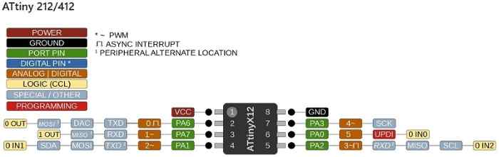
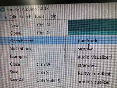
You can see here how the number on the ATtiny412 is not the number I reference in the code, It's the 2 in the orange because the numbers in orange are what correspond to Arduino code. Also for Attiny, I needed a programmer so I decided to use an Arduino with the Jtag library downloaded onto it to turn it into a programmer. To use jtag I had to go to examples then jtag and upload it to my board.
Once I set up the Arduino as my programmer I set up the code for my ATTiny412. I started with the same blink code from last time to make sure that the Attiny was soldered right then I moved on to the more advanced code with two LEDS and made sure that each pin of the ATTiny corresponds with the code correctly using the Attiny412 pinout sheet. As seen in the video below I also connected everything so that we could see it turn on and off the lights.
Bare Metal Programming
Bare metal programming is something that our teacher required us to do and it is in C. It's faster and more compact compared to Arduino code. We worked together to understand the basics in class on a normal Arduino and he is requiring us to blink an LED and maybe more with an ATTiny with bare-metal code.
I started by uploading the normal blink code for an ATTiny412.
void setup() {
  pinMode(3, OUTPUT); //  this sets pin 3 to be an output pin using the pinMode() function.
}

void loop() {
  digitalWrite(2, HIGH); //this turns the light  on
  delay(1000); //this waits 1 second before the next command
  digitalWrite(2, LOW); //this turns the light off
  delay(1000); //this waits 1 second before the next comand
}
then using the pinout for the Attiny 412
I was able to find out what the port pin for the 4th pin on the ATTiny and 2 pins for Arduino code was PA1 or PortA1 and because it's 1 its means for A0 is 0 and A1 is 1 making the light value 1.
while trying to code it I learned that I needed to include #include <avr/io.h> from ChatGPT at the top for bare metal to work with the Attiny412 so after adding that changed the.
void setup() {
  pinMode(3, OUTPUT); //  this sets pin 3 to be an output pin using the pinMode() function.
}
to this
void setup() {
  PORTA_DIR |= (1 << 1); // configure pin PA1 as an output
}
and I swiched this
void loop() {
  digitalWrite(2, HIGH); //this turns the light  on
  delay(1000); //this waits 1 second before the next command
  digitalWrite(2, LOW); //this turns the light off
  delay(1000); //this waits 1 second before the next comand
}
to this
void loop() {
  PORTA_OUT |= (1 << 1); // set pin PA2 high
  delay(1000); // wait for 1 second
  PORTA_OUT &= ~(1 << 1); // set pin PA2 low
  delay(1000); // wait for 1 second
}
And it worked it took a little trile in error becuase I originally though that the PA1's vaule was 2 but it was actually 1 causing my nothign to happen since it was not plugges into PA2.
Final Code
#include <avr/io.h>

void setup() {
  PORTA_DIR |= (1 << 1); // configure pin PA2 as an output
}

void loop() {
  PORTA_OUT |= (1 << 1); // set pin PA2 high
  delay(1000); // wait for 1 second
  PORTA_OUT &= ~(1 << 1); // set pin PA2 low
  delay(1000); // wait for 1 second
}
Rasberry Pi Pico 2040
Data Sheet
Too start thing out I looked though the data sheet and found the pinout and useful inforamtion for the pico.
- It has 8 grounds and 2 powers
- The Raspberry Pi Pico’s GPIO is powered from the on-board 3.3V rail and is therefore fixed at 3.3V
- The Pico exposes 26 of the 30 possible RP2040 GPIO pins
- The simplest way to power Pico is to plug in the micro-USB at 5v
- Reprogramming the Pico Flash can be done using USB
arduino code on Pico
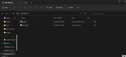
For the Rasberry pico I had no prior experience so I wanted to get it working in Arduino first before trying it in Thonny. So I started by following the pico setup tutorial linked above to learn how to set up the pico for Arduino. I did this by pushing the button on the pico and plugging it in. Once I did this a folder came up with all the information about the pico and that meant it was connected.
Then I went into arduino and uploaded the simple blink code to make sure that it all worked and it did. Here is a video of it working.
The pinout in the datasheet allowed me to use the advanced button and two LED code from earleir again with the correct pins.
void setup() {
  // initialize digital pin LED_BUILTIN as an output.
  pinMode(1, OUTPUT);
  pinMode(2, OUTPUT);
  pinMode(3, INPUT);

}

// the loop function runs over and over again forever
void loop() {
  if(digitalRead(3) == HIGH){
  digitalWrite(2, HIGH);
  digitalWrite(1, LOW);
  }
  else{
  digitalWrite(2, LOW);
  digitalWrite(1, HIGH);
  }
}
Once I put it in it actually worked perfectly and I was super happy. Here is a video of it working.
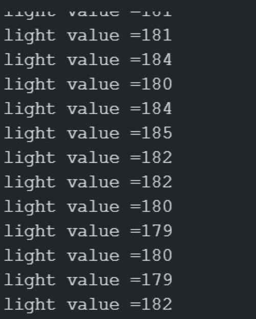
After I got that more advance their was one last thing I wanted to work on before using thonny and that was communication. For communication I hooked up a photo resistor with the code below using an analogRead() and a Serial.print to be able to see what the code was actually getting. with this I was able to see what light values the photo resistor was getting from the room
void setup()
{
  Serial.begin(9600);

}

void loop()
{
  int raw = analogRead(2);
  Serial.print(" light value =");
  Serial.println(raw);
  delay(250);
}
Here is an image of the serial moniter showing the light value.
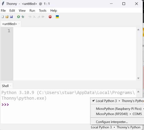
python code on pico
To learn how to code python on the pico I followed the MicroPython1 tutorials that my teacher/local evaluator gave us.
I started by downloading microPython and downloading it onto the pico. Then I downloaded Thonny so that I can code in python on the pico.
After figuring all this out and using the data sheet to see that pin 25 in connected to the Led on the board I looked at the tutorial for how python works. then I made the LED blink with the code below.
import machine
import utime
led_onboard = machine.Pin(25, machine.Pin.OUT)

while True:
    led_onboard.value(1)
    utime.sleep(1)
    led_onboard.value(0)
    utime.sleep(1)
after the basic blink I wanted to learn how to do inputs in python, so I asked chatgpt and it told me
button = Pin(14, Pin.IN, Pin.PULL_DOWN) #defines a input for button
after it gave me how to define one I already knew that it gives off true and false values so I just said if button true toggle lights here is the code.
from machine import Pin
import time

led = Pin(16, Pin.OUT)
button = Pin(15, Pin.IN, Pin.PULL_DOWN)

while True:
    if button.value():
        led.toggle()

    time.sleep(0.1)
lastly, I wanted to try to get a little more advanced by switching lights on and off with the press of a button so I got three lights and wanted to turn them on one by one. To do this I added an extra variable called light and made it equal to 1. and every time a light turned on it would increase until it gets to three. then it would reset and go over again. And every time the light value changes a different led would turns on. Here is the code
from machine import Pin
import time

led_1 = Pin(16, Pin.OUT)
led_2 = Pin(17, Pin.OUT)
led_3 = Pin(18, Pin.OUT)
button = Pin(15, Pin.IN, Pin.PULL_DOWN)
light = 1

while True:
    if button.value():
        if light == 1:
            led_1.value(1)
            led_2.value(0)
            led_3.value(0)
            light = light + 1
        elif light == 2:
            led_1.value(0)
            led_2.value(1)
            led_3.value(0)
            light = light + 1
        elif light == 3:
            led_1.value(0)
            led_2.value(0)
            led_3.value(1)
            light = 1


    time.sleep(0.175)
Putting it all Together
And with that all out of the way I started to get confident in coding again and wanted to get into the more advanced stuff thats not lights.
servo
I started with turing a Servo. I looked through the example servo code for swing in arduino and modled my code based off of that.
I started with this code to include the servo library and then make a servo object for me to control. After that what I did was make a interger pos to show where the position of the servo/the degree it has turned. Then I put together the servo on the pin and the object to make them the same thing. lastly I wrote the original position of the servo as 0 degrees.
#include <Servo.h>
Servo myservo;  // create servo object to control a servo
// twelve servo objects can be created on most boards

int pos = 0;    // variable to store the servo position

void setup() {
  myservo.attach(8);  // attaches the servo on pin 9 to the servo object
  myservo.write(0);
}
then after writing this I wrote this code to actually change the position of the servo back and forth so it keeps going infinitly
void loop() {

for (pos = 0; pos <= 180; pos += 2) { // goes from 0 degrees to 180 degrees
    // in steps of 1 degree
    myservo.write(pos);              // tell servo to go to position in variable 'pos'
    delay(15);                       // waits 15ms for the servo to reach the position
  }
  for (pos = 180; pos >= 0; pos -= 2) { // goes from 180 degrees to 0 degrees
    myservo.write(pos);              // tell servo to go to position in variable 'pos'
    delay(15);                       // waits 15ms for the servo to reach the position
  }
}
Once I finished writing the code I then uploaded it the my arduino and wired up the servo here is the result.
sorry for shaky video I was on a plane.
IR Remote
After making the servo move I decided to do communication through an IR sensor and an IR remote to start out I dowloaded the IR remote library from arduino to be able to use the sensor and remote. that library came with an example code that looked at to understand how the IR sensor worked. once I figured that out I would make my code one that serial printed the value of the button I pressed. Below is my code.
#include <IRremote.hpp>// includes library
#define IR_RECEIVE_PIN 8 // defines IR_RECEIVE_PIN as 8

void setup() {
  Serial.begin(9600);
  IrReceiver.begin(IR_RECEIVE_PIN); // starts recieving pin 8

}

void loop() {
  if(IrReceiver.decode()){//if gets value from remote decode
   IrReceiver.resume(); //start reciving again
   Serial.println(IrReceiver.decodedIRData.command); //print the value decoded
  }

}
below is an video of the code working and an image of the values showing in the serial monitor.

IR Remote Servo Controller
Once I was finished with these two projects I decided it would be fun to put them togther and be able to control the servo with the remote. So I started by running all the buttons on the remote through the IR remote code to see what value each button was. when doing that here is what I got.
#define IR_BUTTON_0 22
#define IR_BUTTON_1 12
#define IR_BUTTON_1 24
#define IR_BUTTON_3 94
#define IR_BUTTON_4 8
#define IR_BUTTON_5 28
#define IR_BUTTON_6 90
#define IR_BUTTON_7 66
#define IR_BUTTON_8 82
#define IR_BUTTON_9 74
#define IR_BUTTON_FAST_FORWARD 67
#define IR_BUTTON_REVERSE 68
after getting all the values and then defining them in my code imported the IR remote library and servo library. I aslo created a servo object and pos interger just like in the servo code. then in the setup code wrote this.
void setup() {
  Serial.begin(9600);
  IrReceiver.begin(IR_RECEIVE_PIN);
  myservo.attach(8);  // attaches the servo on pin 9 to the servo object
  myservo.write(0);

}
once i setup all my code I had to make an if statement for the fast forward and reverse button that would turn the servo left and write as seen below.
void loop() {
  if(IrReceiver.decode()){
   IrReceiver.resume();
   int command = IrReceiver.decodedIRData.command;
   switch (command) {
    case IR_BUTTON_FAST_FORWARD: {
      myservo.write(180);
      break;
    case IR_BUTTON_REVERSE: {
      myservo.write(pos);              // tell servo to go to position in variable 'pos'
      break;
    }
    }
   }
  }
}
And that was my whole code. It works just like I imagined. while making it the remote control occasinally would not put in the right value but there was no way to fix it and I just had to deal with it.
Once I was done making the servo making this circuit I realised hwo im going to make my blocks move up and down. im going to directly connect a block the the top of the moving circle using a dowl so that way when lays at 180 degrees it is down and when i move it to 90 degrees it pushes the dowl up pushing the block up.
Summary
This week I Re-learned Arduino and ATTiny412 which I will probably use for controlling my servo motors for my final project. I also learned how to code a raspberry pi pico through Arduino and python that I might use for networking on my final project.