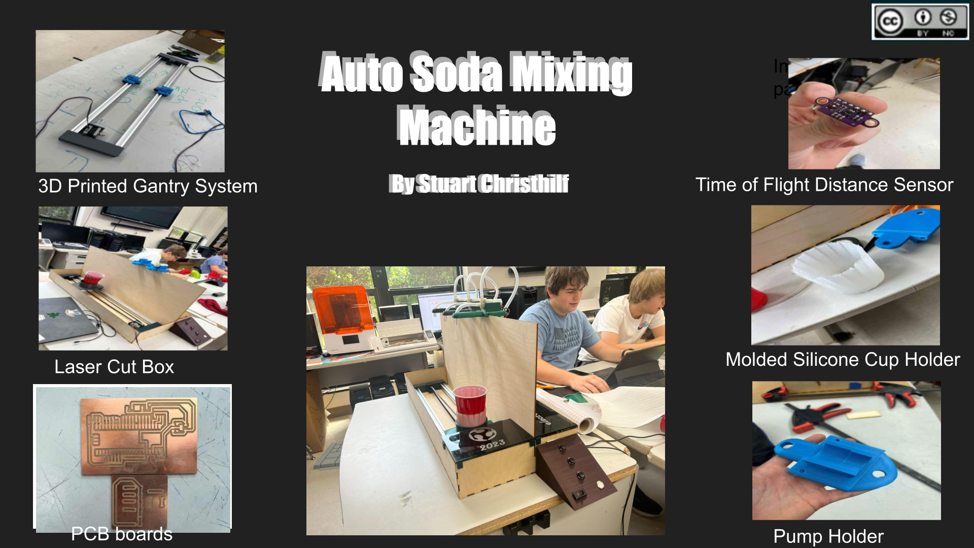
Final Project
The Switch
At week 10 I realized that I truly did not like my previous project idea and was not having any fun working on any parts of it. I realized this because when working on the Soda Machine during week 10 even though their where parts that sucked every little success made me so happy, but any success with this project does not give me anything. So I decided so Switch projects and upgrade and improve the version one of the soda machine we made into a more refined process with many improvements. I just do not find my previous project worth it, So I would rather put my time and passion into something that I have fun making.
Copyright
For a patent for my project I want a creative commons license, this way I could commercialize my project and make money off of it if I truly wanted too. And as for which kind of creative common license I will go with a (Attribution-NonCommercial 4.0 International)[https://creativecommons.org/licenses/by-nc/4.0/] this way anyone can build on my project and improve it in any way they want but if anyone does, they have to cite me along with not using it for any profit of their own just in case I do try and sell my project.
BOM
Materials
| Part | Amount | URL | Cost per Piece |
|---|---|---|---|
| Zeelo 5M GT2 Timing Belt 6mm Width + 4pcs 20 Teeth 5mm Bore Timing Pulley Wheel + 4pcs Idler + 8pcs Tensioner Spring Torsion + 4pcs Gear Clamp Mount Block with Allen Wrench for 3D Printer | 1 | Amazon Link | $16.99 |
| uxcell DC 12V 300mA 1300ml Water Flow Self Priming Diaphragm Micro Water Pump for Coffee Machine, Water Dispenser | 3 | Amazon Link | $16.34 |
| STEPPERONLINE Stepper Motor Nema 17 Bipolar 40mm 64oz.in(45Ncm) 2A 4 Lead 3D Printer Hobby CNC | 2 | Amazon Link | $12.99 |
| Qunqi 2Packs L298N Motor Drive Controller Board Module Dual H Bridge DC Stepper For Arduino | 1 | Amazon Link | $8.99 |
| Vis Viva Raspberry Pi Pico W (Wireless, WiFi) + Raspberry Pi Logo Sticker (1Pack, Wireless) | 1 | Amazon Link | $12.95 |
| ALITOVE AC 100-240V to DC 12V 10A Power Supply Adapter Converter Transformer 12 Volt 10 Amp 120W with 5.5mm x 2.5mm 2.1mm DC Output Jack for 5050 3528 LED Strip Light CCTV Cameras 3D Printer | 1 | Amazon Link | $20.99 |
| T-Bar Aluminum Track | 2 | Walmart Link | $26.00 |
| Time of flight Sensor | 2 | Amazon link | 9.99 |
| Buttons | |||
| Switch | |||
| Wires | |||
| PLA plastic | |||
| PCB boards | |||
| Wood | |||
| Clear Plastic Tubing | |||
| lever action switch |
Plans
For this project I want to take my Week 10 Group Project The Soda Machine and upgrade it into a more refined Final Project. Here is the link to my work during week that I plan to build upon. To do this I plan to add sensors to every stop so that it is always under the pumps for the machine. I also need to take it off of Arduino mega and move it to a Raspberry Pico 2040 for controlling everything. Along with this I will mill my own boards for every piece instead of using a bread board. I also want to put nozzles and something to hold those nozzles in place, so they don't move while pumping liquids out. I also plan on coding it with the math to always fill the cup, so if you press 2 drinks it will fill it half-and-half and so on. That is all the electrical and mechanical changes, but I also want to add am area under the carriage so if a liquid misses the cup it catches it and drains it all out. I also want to add Neo pixel lights next to the buttons to show if they have been pressed or not. Lastly one of the biggest problems with our original soda machine was that the bottom carriage would bind all the time causing stress to the stepper motor and the whole system. This was because the whole skeleton was too rigid So I plan on putting a spring in between both sides of the aluminum T-bar so that it has a little give making it.
End Caps
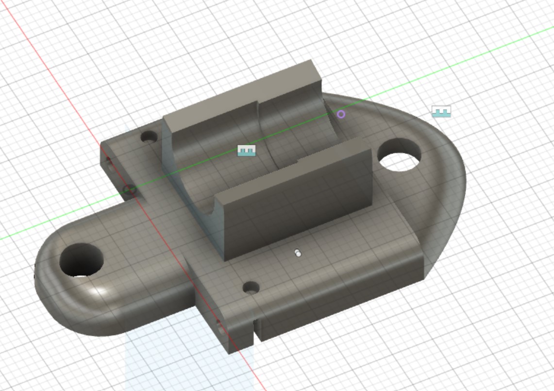
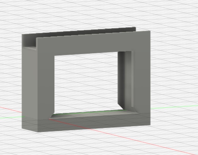
One of the problems with the last version was how the end caps where to thin and would break a lot of the time. We also needed to print on end cap in half just to get the bearing in there. So I decided to change this by making everything thicker, and adding an extra wall to hold the stepper motor in. To fix the pully issue I made a completely separate attachment to put the pully in that fits right into the end cap. With these changes the end caps have less chance of breaking and more of a chance at actually being square and strong instead of being held together by glue in the middle. Here is an image of my fusion designs for the project.
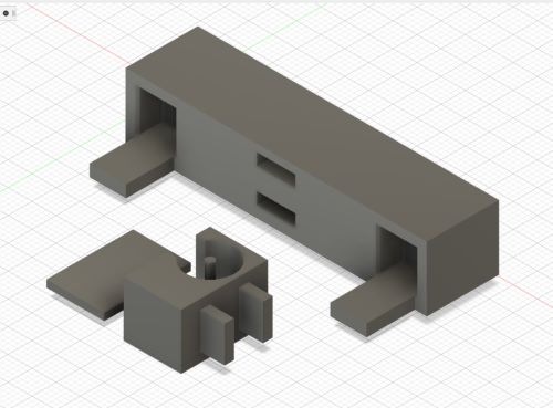
With this design you put the bearing in its separate holder and then glue the side onto it. And then you glue the whole extra piece into the end cap.
It is printed as press fit but gluing it will help keep it in when it binds and puts extra pressure on the pully.
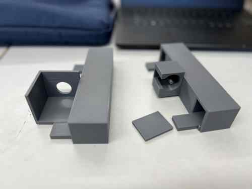
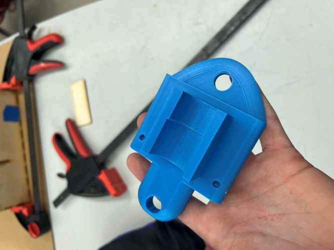
Here is a picture of my new end caps along with them put together with the machine.
Wheel guides
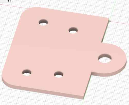
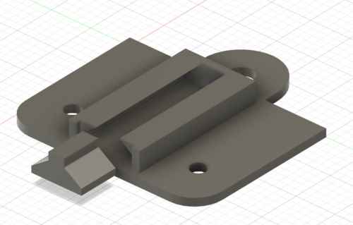
The next problem I wanted to fix was to fix of the main reasons the original kept binding. And that was because of the plate being glued and fixed straight onto the wheel guides, so they had no give. Without any give if the rails where not perfectly straight then it would try to expand the distance but not be able to causing the wheels to bind. To fix this I designed a system to attach the plate on a piece that slides in a area on top of the wheel guide to give the plate some give. Here is a picture of the original wheel guide designed by Ginny Foster and my edited version.
(original)
(new)
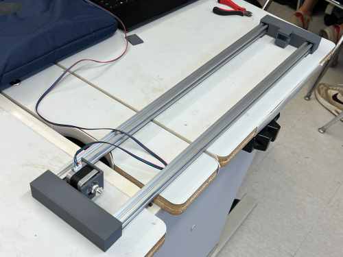
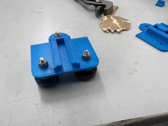
After printing it I had too put the wheels onto it. To do this I put the wheel on a screw then put a spacer nect to the wheell I then put the screw into the whole and used a hex nut to tighten and lock the wheel inplace. After doing this with every wheel here are the results.
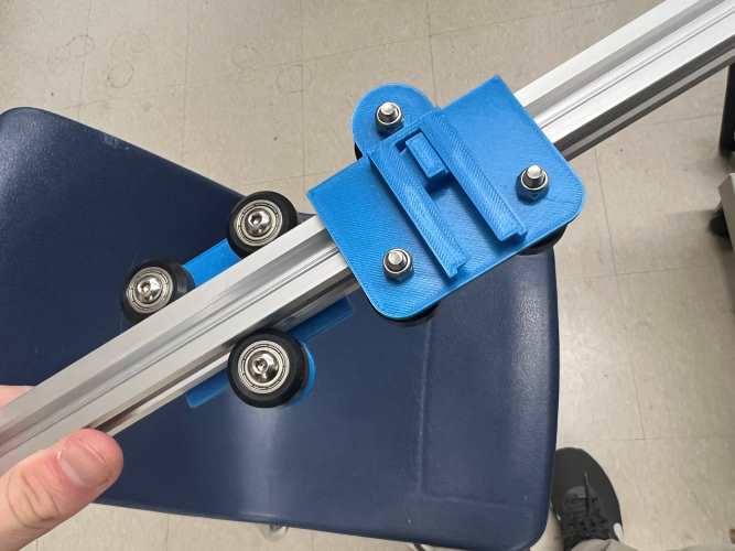
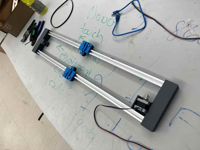
And here is what it all looks like together now.
Electronics
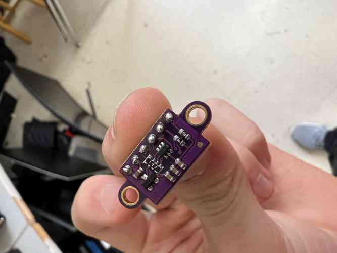
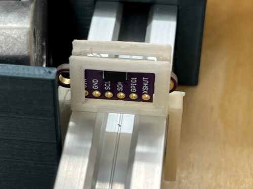
Time Of Flight Sensor
To start of with electronics I needed to figure out how the Time Of Flight distance sensor worked. I did this during Input Week and ended up with this result that I will work into my final project to see how far away the cup is from the pump.
#include <Wire.h>
#include "SparkFun_VL53L1X.h" //Click here to get the library: http://librarymanager/All#SparkFun_VL53L1X

//Optional interrupt and shutdown pins.
#define SHUTDOWN_PIN 2
#define INTERRUPT_PIN 3
#define ledOne 15
#define ledTwo 14
#define ledThree 13

SFEVL53L1X distanceSensor;
//Uncomment the following line to use the optional shutdown and interrupt pins.
//SFEVL53L1X distanceSensor(Wire, SHUTDOWN_PIN, INTERRUPT_PIN);

void setup(void)
{
  Wire.begin();

  Serial.begin(115200);
  Serial.println("VL53L1X Qwiic Test");

  if (distanceSensor.begin() != 0) //Begin returns 0 on a good init
  {
    Serial.println("Sensor failed to begin. Please check wiring. Freezing...");
    while (1)
      ;
  }
  Serial.println("Sensor online!");
   pinMode(ledOne, OUTPUT);
   pinMode(ledTwo, OUTPUT);
   pinMode(ledThree, OUTPUT);
}

void loop(void)
{
  distanceSensor.startRanging(); //Write configuration bytes to initiate measurement
  while (!distanceSensor.checkForDataReady())
  {
    delay(1);
  }
  int distance = distanceSensor.getDistance(); //Get the result of the measurement from the sensor
  distanceSensor.clearInterrupt();
  distanceSensor.stopRanging();
  Serial.print("Distance(mm): ");
  Serial.print(distance);
  float distanceInches = distance * 0.0393701;
  float distanceFeet = distanceInches / 12.0;
  Serial.print("\tDistance(ft): ");
  Serial.print(distanceFeet, 2);
  Serial.println();

  if(distance < 250){
    digitalWrite(ledOne, HIGH);
  }
  else{
    digitalWrite(ledOne, LOW);
  }
  if(distance < 500 && distance > 250){
    digitalWrite(ledTwo, HIGH);
  }
  else{
    digitalWrite(ledTwo, LOW);
  }
  if(distance < 750 && distance > 500){
    digitalWrite(ledThree, HIGH);
  }
  else{
    digitalWrite(ledThree, LOW);
  }
}
Planning
It was at this point that we started to get into the endgame and I needed to plan out my project and what times I would do everything from June 6 - 14.
| Day | What I need to do |
|---|---|
| June 5th | On this day I plan on finishing all y cad designs by designing the plate and any electronic holders along with a way to attach the up and down mixer mover. Lastly I want to make sure all the materials I need for this project have been ordered so that I can get them on time. |
| June 6th | On this day I want to make sure all my 3d prints fit and then redesign them if they don't. I also plan on designing the laser cut for the box around the carriage |
| June 7th | On this day I would like to completely breadboard out all my electronics and start designing some PCB boards for all of it. |
| June 8th | Today I Would like to finish designing the PCB boards and go ahead and mill them all out. While they are milling I would like to go ahead and laser cut out my basic box for my entire system to hold everything together. |
| June 9th | On this day I Want to put everything together and start coding to all. Figure out what I need to fix and add to make it all work |
June 5th
Today I started by getting my 3d prints for the end caps..
The next thing I had to do was design the plate that could connect to the sliders I had already made. To do this I made the plate and gave it some legs that would fit in the sliders so that it could connect to everything. Here is my design, and it once it was 3D printed.
Once I had it all printed out the plate I tested it all the carriage and here is a video of the whole thing.
And as seen here it worked great. This was a perfect sign for me and really motivated for me to continue. Next I had to design and 3d print the new pump holders so that I could hold the pumps in place for the liquids. To do this I designed it to fit onto a 1/8" inch wall which is what I plan to make the backdrop. Here is an image of the design and the actual 3d print.
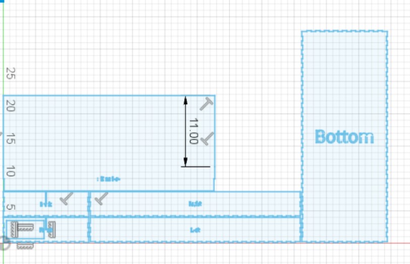
After I had finished making the pumps I decided to design the box for the whole machine before the day ended. Here is an Image of my design.
June 6th
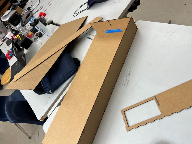
After yesterday I started out the day by cutting out my box, but I started with a test cut on cardboard as seen here.
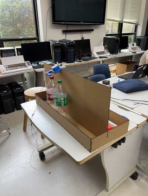
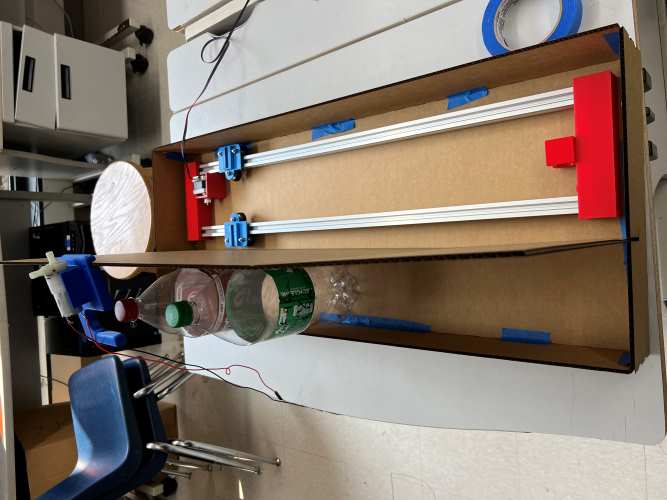
After making sure it all fit I decided to test the gantry carriage system in the cardboard before the wood. To do this I just bread boarded out with the pico and motor driver.
After making sure this worked I then decided to cut it on wood and wood glue it all together.
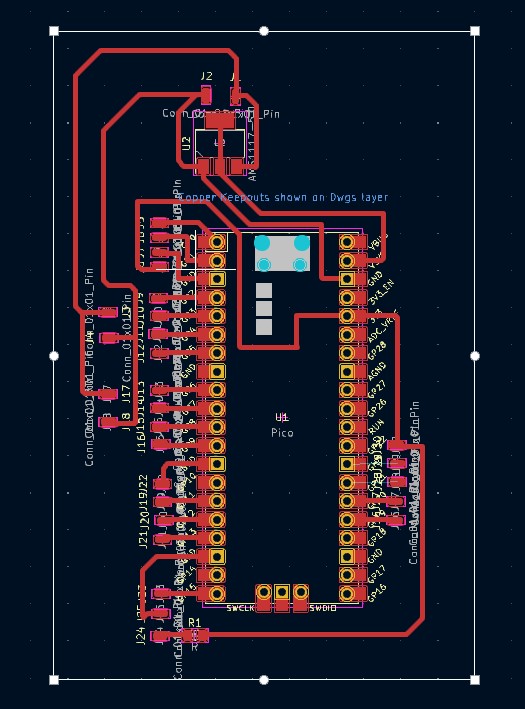
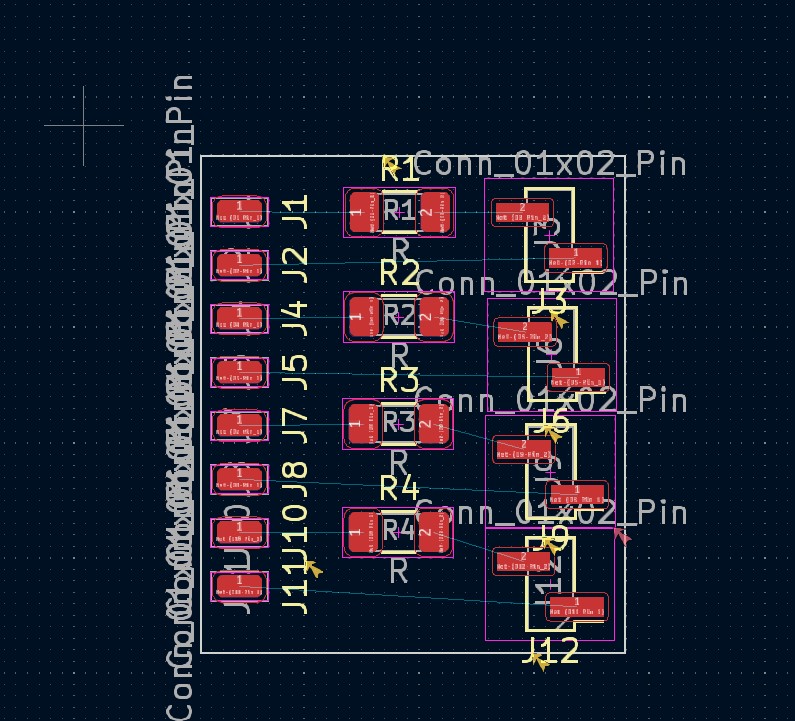
Before the day ended I decided to design my boards to mill tomorrow. To do this I decided that I would do two boards, one on the control panel and another that holds the raspberry pi pico, and all the other devises I needed to control such as 3 pumps, 1 stepper motor, and a time-of-flight sensor. Here is an image of both the boards.
June 7th
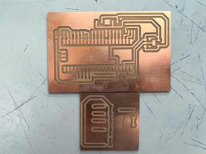
Today I started out by milling the boards. I used the bantam milling machine and cut out both boards at the same time as seen here.
After milling out the board I decided to go ahead and solder the power to the switch and the pico just so that I could see if ti all worked together. I also got to test if naming a code main.py would really make it run on power up. Here is a video of it all working.
Now that I knew my code and boards would work I soldered all my buttons onto the button board as seen here.
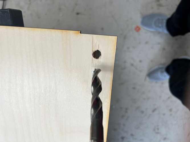
Before soldering the rest I realized that I would actually need wholes for wires and power to pass through in my box, so I drilled them all into the box.
After making ways for all the wiring to be possible I then had time to solder on the motor driver and servo motor to my board before the day ended. Here is a video of the carriage going back and forth.
June 8th
My goal for today was to get buttons working and to get the limit action switch to work also. To start things off I had already soldered my buttons onto the board, but I still had to solder them to the Pico. Once this was done using my own knowledge of python and a little assistance from ChatGPT I ended up with a test code that made it so that the 3 buttons moved the plate forward 50, 100, 150 steps forward. And the silver start button moved the plate back 50 steps. Here is a video of it working.
Once I got this working I then soldered the Limit action switch to the PCB and changed the code so then when the silver button is pressed it makes the plate go back until the limit action switch is pressed so that it zeros out the whole system. Here is what it looked like after that.
Before ending the day I decided to get the system ready to add the Time of Flight VL53l0x sensor.
To prep for the sensor I needed to design a holder for the sensor so that it could be held straight so that it does not see something else. To do this I just made a open holder that you can slide the sensor into that would grab onto the t-bar aluminum tracks as seen here.
June 9th
It was at the start of today that I realized that my wiring was awful and that I was going to need a new plan.
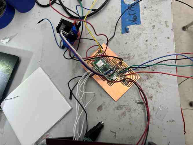
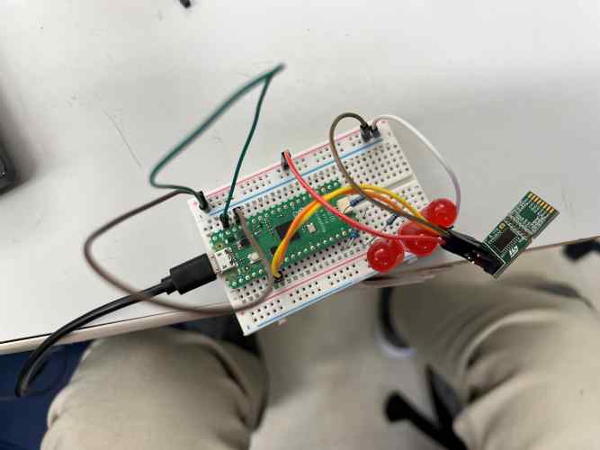
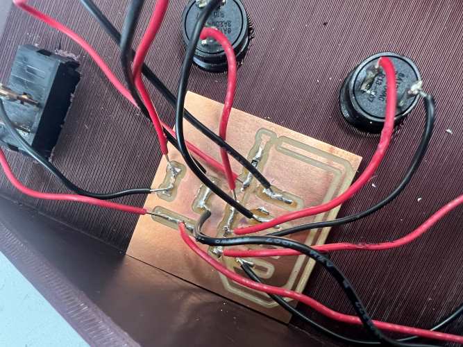
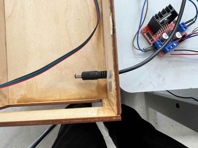
After ripping a trace I decided to re mill my board and then re solder the whole thing with pin headers so that I could easily wire my whole project. Here is a video of me soldering and a picture of my wiring after soldering
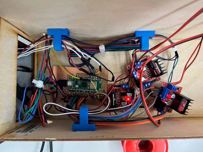
Here in my wiring you can see all my components. I have 3 H-bridges, one of which controls the stepper, motor and the other two so that I can control the pumps. You can see my Raspberry Pi Pico W RP2040 as my microcontroller. You can see my 12v, 5amp power supply connected to everything with a voltage regulator in between.
June 10th
Today I got my pumps working using the code below.
import machine

# Pin assignments for L298N H-bridge
motor1_in1 = machine.Pin(6, machine.Pin.OUT)
motor1_in2 = machine.Pin(7, machine.Pin.OUT)

motor2_in1 = machine.Pin(8, machine.Pin.OUT)
motor2_in2 = machine.Pin(9, machine.Pin.OUT)

# Function to control motor direction
def control_motor(motor_in1, motor_in2, direction):
    if direction == 'forward':
        motor_in1.on()
        motor_in2.off()
    elif direction == 'backward':
        motor_in1.off()
        motor_in2.on()
    elif direction == 'stop':
        motor_in1.off()
        motor_in2.off()
    else:
        raise ValueError('Invalid direction')

# Example usage: Run both motors forward for 2 seconds
control_motor(motor1_in1, motor1_in2, 'forward')
control_motor(motor2_in1, motor2_in2, 'forward')
machine.sleep(2000)

# Stop both motors
control_motor(motor1_in1, motor1_in2, 'stop')
control_motor(motor2_in1, motor2_in2, 'stop)
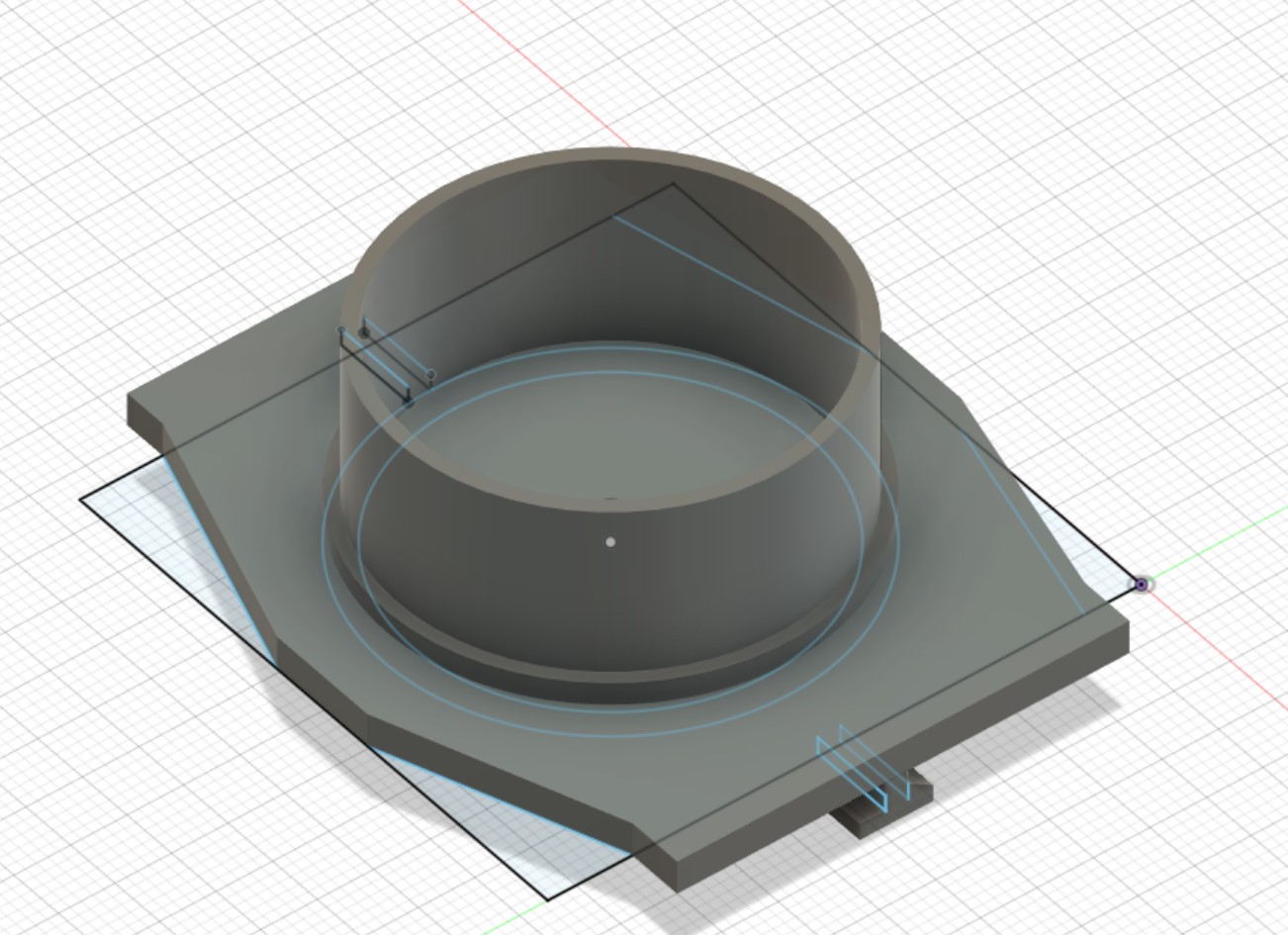
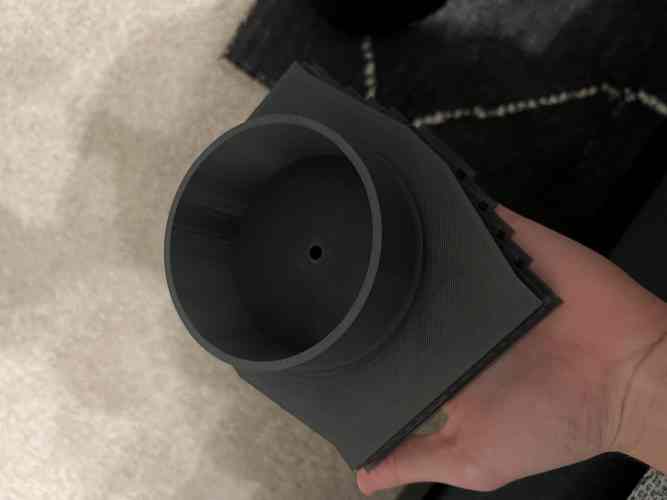
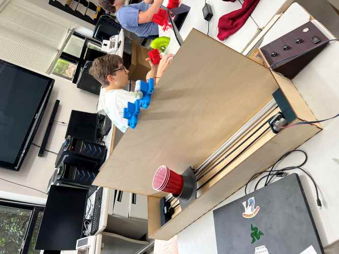
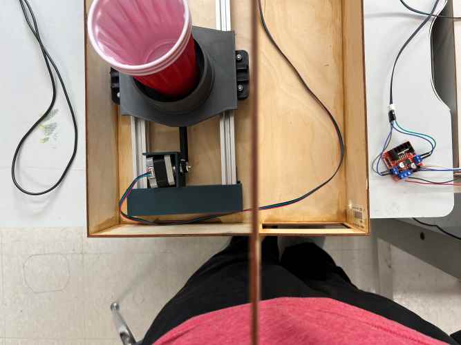
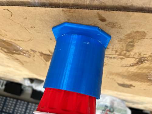
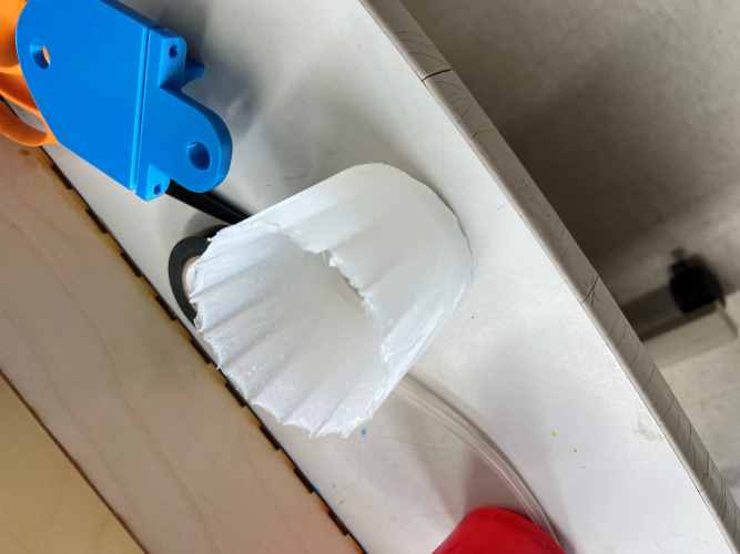
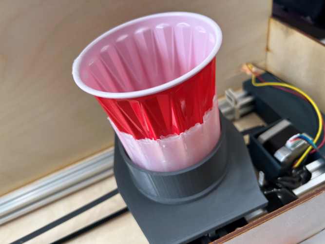
Today I also molded a cup holder to out of silicone to put in the plate to help absorb some vibration and cause less spoilage. To do this I used one of the hold cup holders because the measurements are the same diameter and put a red solo cup in so that the could cast silicone as seen below.
June 11th
Today I coded the whole project. But before that I noticed that even if my wiring looks a lot better it still is not the best, so I laser cut some covers on black acrylic to somewhat cover it up.
After this I had to code the whole project. Here is a video of me coding, and my maybe final code listed below with comments to help explain it all.
from machine import Pin
from time import sleep
from machine import Pin, I2C
from vl53l0x import VL53L0X

#extra variables
step = 0
sodas = 0
fill_cup = 10
button1_hit = 0
button2_hit = 0
button3_hit = 0
button4_hit = 0

#setting up time of flight sensor
sda = Pin(0)
scl = Pin(1)
id = 0
i2c = I2C(id=id, sda=sda, scl=scl)
tof = VL53L0X(i2c)
budget = tof.measurement_timing_budget_us
print("Budget was:", budget)
tof.set_measurement_timing_budget(40000)
tof.set_Vcsel_pulse_period(tof.vcsel_period_type[0], 12)
tof.set_Vcsel_pulse_period(tof.vcsel_period_type[1], 8)

#setting up buttons
# Button GPIO Pins
button1_gpio = 18 # start
button2_gpio = 19 # lower
button3_gpio = 21  # middle
button4_gpio = 20  # upper
# Button Pins
button1 = Pin(button1_gpio, Pin.IN, Pin.PULL_UP)
button2 = Pin(button2_gpio, Pin.IN, Pin.PULL_UP)
button3 = Pin(button3_gpio, Pin.IN, Pin.PULL_UP)
button4 = Pin(button4_gpio, Pin.IN, Pin.PULL_UP)
# Variables to track button states
button1_state = 1
button2_state = 1
button3_state = 1
button4_state = 1

#setting up limit action switch
# Limit Action Switch GPIO Pin
limit_switch_gpio = 15
#limit pin
limit_switch = Pin(limit_switch_gpio, Pin.IN, Pin.PULL_DOWN)

#setting up stepper motor
#pins
IN1 = Pin(2, Pin.OUT)
IN2 = Pin(3, Pin.OUT)
IN3 = Pin(4, Pin.OUT)
IN4 = Pin(5, Pin.OUT)
#pin array
pins = [IN1, IN2, IN3, IN4]
#turning sequence for pins
sequence_clockwise = [[1, 0, 0, 0], [0, 1, 0, 0], [0, 0, 1, 0], [0, 0, 0, 1]]
sequence_counterclockwise = [[0, 0, 0, 1], [0, 0, 1, 0], [0, 1, 0, 0], [1, 0, 0, 0]]
#stepper paramiters
steps_per_revolution = 200
delay = 0.001
# Set all pins to LOW initially
for pin in pins:
    pin.value(0)

#pumps
#two
motor2_in1 = machine.Pin(6, machine.Pin.OUT)
motor2_in2 = machine.Pin(7, machine.Pin.OUT)
#three
motor3_in1 = machine.Pin(8, machine.Pin.OUT)
motor3_in2 = machine.Pin(9, machine.Pin.OUT)
#one
motor1_in1 = machine.Pin(12, machine.Pin.OUT)
motor1_in2 = machine.Pin(13, machine.Pin.OUT)

def step_forward(num_steps):
    sequence = sequence_clockwise
    for _ in range(num_steps):
        for step in sequence:
            for i in range(len(pins)):
                pins[i].value(step[i])
            sleep(delay)

def step_backward(num_steps):
    sequence = sequence_counterclockwise
    for _ in range(num_steps):
        for step in sequence:
            for i in range(len(pins)):
                pins[i].value(step[i])
            sleep(delay)

def stepper_idle():
    for pin in pins:
        pin.value(0)

def button_callback(pin):
    global button1_state, button2_state, button3_state, button4_state, button1_hit, button2_hit, button3_hit, button4_hit

    if pin == button1 and button1_state == 0:
        if button1_hit == 0:
            button1_hit = 1
            sleep(.1)
        elif button1_hit == 1:
            button1_hit = 0
            sleep(.1)
        sleep(.1)

    elif pin == button2 and button2_state == 0:
        if button2_hit == 0:
            button2_hit = 1
            sleep(.1)
        elif button2_hit == 1:
            button2_hit = 0
            sleep(.1)
    elif pin == button3 and button3_state == 0:
        if button3_hit == 0:
            button3_hit = 1
            sleep(.125)
        elif button3_hit == 1:
            button3_hit = 0
            sleep(.125)
    elif pin == button4 and button4_state == 0:
        if button4_hit == 0:
            button4_hit = 1
            sleep(.125)
        elif button4_hit == 1:
            button4_hit = 0
            sleep(.125)
    button1_state = button1.value()
    button2_state = button2.value()
    button3_state = button3.value()
    button4_state = button4.value()

button1.irq(trigger=Pin.IRQ_FALLING | Pin.IRQ_RISING, handler=button_callback)
button2.irq(trigger=Pin.IRQ_FALLING | Pin.IRQ_RISING, handler=button_callback)
button3.irq(trigger=Pin.IRQ_FALLING | Pin.IRQ_RISING, handler=button_callback)
button4.irq(trigger=Pin.IRQ_FALLING | Pin.IRQ_RISING, handler=button_callback)

def zero_machine():
    while limit_switch.value() == 0:
        step_backward(1)

def move_to_place(place):
    print("move to place was called")
    while True:
        distance = tof.ping() - 50
        if distance < place:
            step_forward(1)
        elif distance > place:
            step_backward(1)
        else:
            break
        sleep(delay)  # Add a small delay between steps for smoother motion

    stepper_idle()

while True:

    button1_state = button1.value()
    button2_state = button2.value()
    button3_state = button3.value()
    button4_state = button4.value()
    #zero machine when turned on
    if step == 0:
        zero_machine()
        step = 1
        sodas = 0
    elif step == 1:
        if button1_hit == 1:
            if button2_hit == 1:
                sodas += 1
            elif button3_hit == 1:
                sodas += 1
            elif button4_hit == 1:
                sodas += 1
            step = 2
    elif step == 2:
        if button2_hit == 1:
            move_to_place(136)
            motor1_in1.on()
            motor1_in2.off()
            sleep(fill_cup/sodas)
            motor1_in1.off()
            motor1_in2.off()
        if button3_hit == 1:
            move_to_place(236)
            motor2_in1.on()
            motor2_in2.off()
            sleep(fill_cup/sodas)
            motor2_in1.off()
            motor2_in2.off()
        if button4_hit == 1:
            move_to_place(330)
            motor3_in1.on()
            motor3_in2.off()
            sleep(fill_cup/sodas)
            motor3_in1.off()
            motor3_in2.off()
        step = 3
    elif step == 3:
        zero_machine()
        sleep(5)
        step = 0
        button1_hit = 0
        button2_hit = 0
        button3_hit = 0
        button4_hit = 0

     # Perform other tasks or pause the program
    sleep(0.125)

    # Check if all buttons are released
    if button1_state == 1 and button2_state == 1 and button3_state == 1 and button4_state == 1:
        stepper_idle()
    print(button1_hit)
    print(button2_hit)
    print(button3_hit)
    print(button4_hit)
    print()
And lastly here is that code working.
All thats left now is to add the tubing and test with liquids which I have to wait till tommorow becuase thats when tubing gets here.
Final result
After getting and attaching the tubing here is a video of everything working.
Slide and Presentation