Output Devices
Task for Week 9
- Group Assignment
- - measure the power consumption of an output device
- Individual Assignment
- - Add an output device to a microcontroller board you've designed, and program it to do something
Group Assignment
Link to our group assignment is here
Lesson learnt
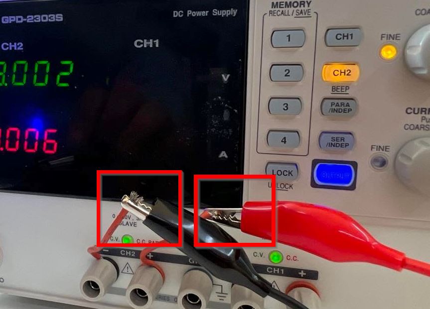
- 1. We can either keep the applied voltage constant or the current constant according to what we want to calculate.
- 2. Always make sure to click on "Output" to get the readings once we have set the voltage or the current.
- 3. Make sure that the positive and negative clips don't touch one another.
Individual Assignment
This week is also going to be an Electronic week where we are asked to work on an output device to a microcontroller board that I've designed. In the previous week, I designed a board using ATTINY1614 and it was quite fun. This week I wanted to work towards my final project so decided to design a board using ESP32 WROOM as the microcontroller.
Designing My board using ESP32
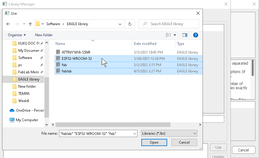
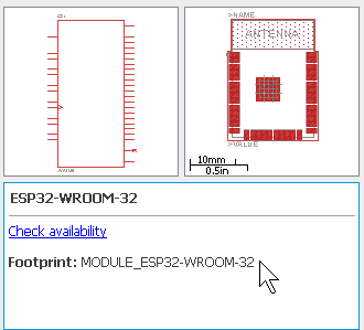
- I've been comfortable using eagle for designing my PCB.So first added the footprint and symbol of ESP32 and added the components that.
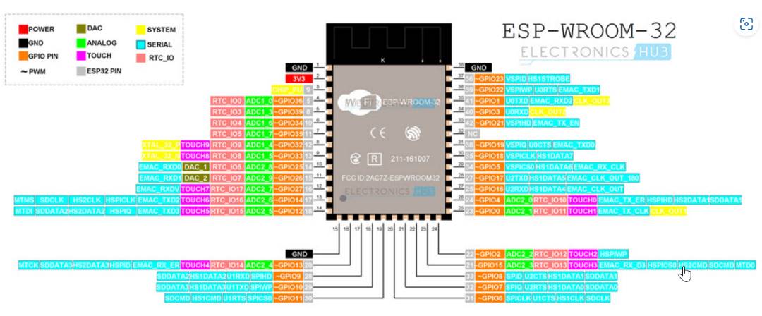
- ESP32
- Slight Switch
- FDTI
- Resistors
- Capacitors
- Voltage regulator
- 4-pin Headers
- LED
- Tact Switch
- Power Jack
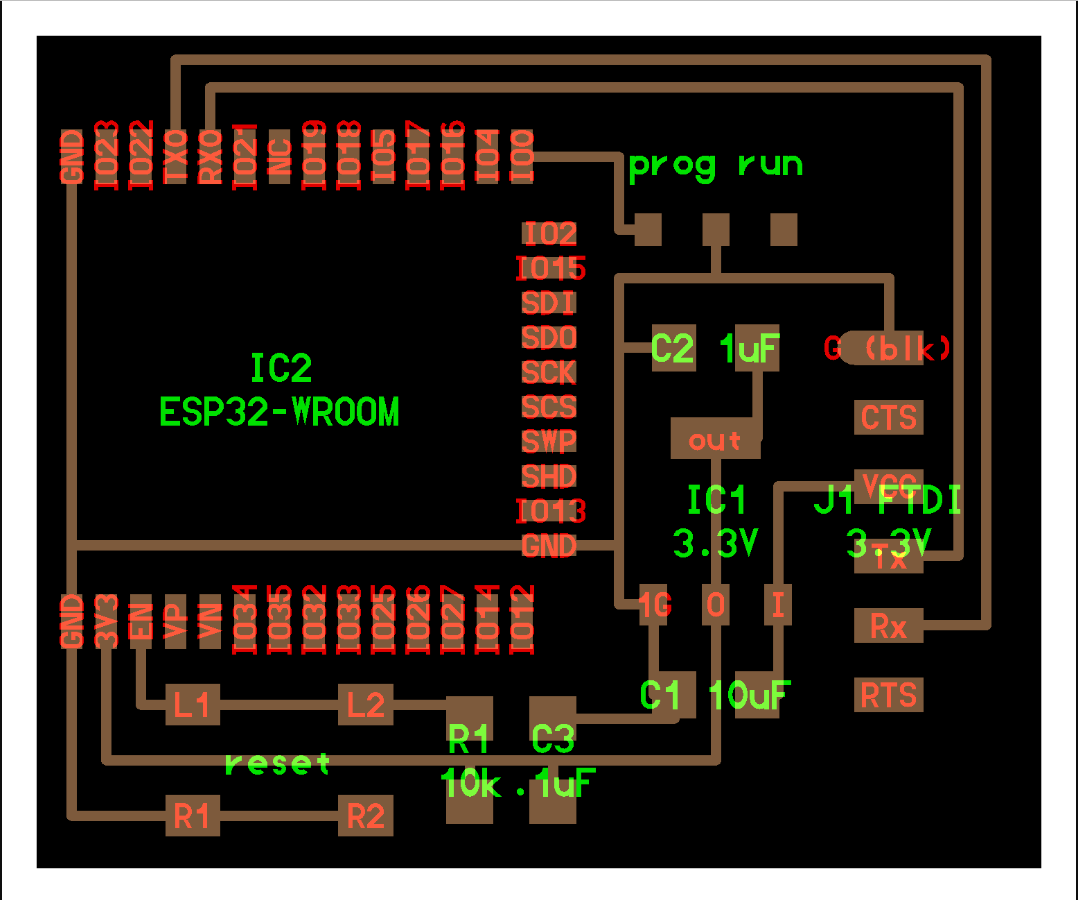
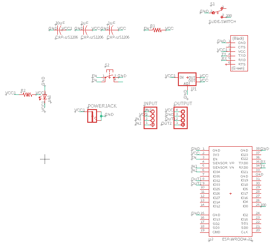
- Then after adding the components, renamed the components and made the electrical connections.
- Referred the ESP32-WROOM Pinout and ESP32-WROOM-32 board.
- After being done with the schematic design, checked the ERC(electrical rule check).
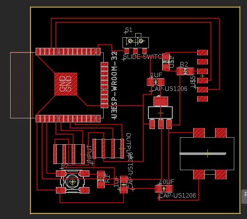
- Then generated the board design from the schematic design as shown below.
- Once I generated the board design, I moved all the components to the design window of the board design. I started arranging the components based on the best possible fit. Then I manually routed the connections.
- Then after the connections were completed run the DRC(Design rule check).
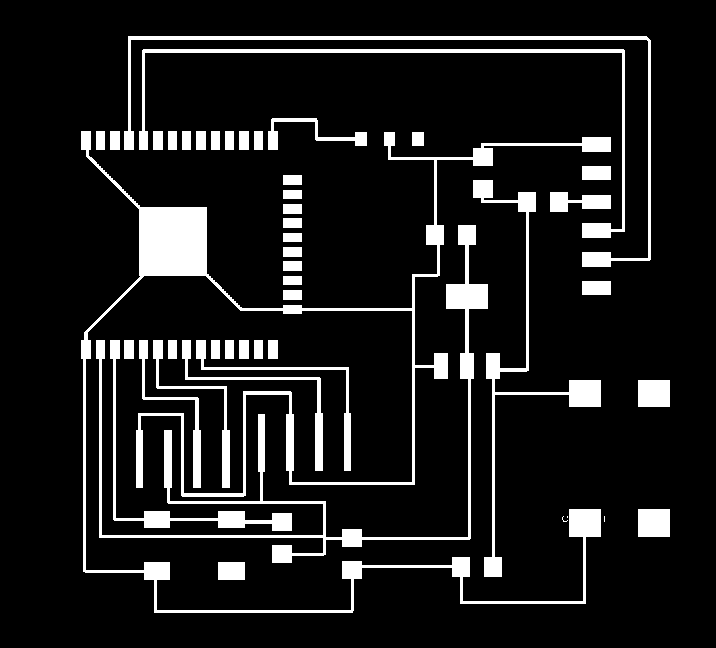
- Then exported the outline and traces of my board in png format. To know more how to do it, refer Week 6 Assignment
- Then converted png to rml using Mods and to know more, go through Week 8 Assignment
- Milled the board using SRM-20. My board was ready to be soldered. Gathered the components and started soldering. In the previous, my soldering was not done properly, so tried to improve this time.

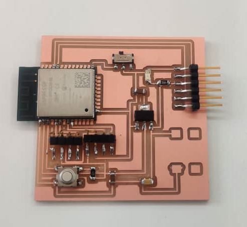
Buzzer as Output Device with Esp32 Board
- Keeping my final project in mind, I used buzzer in place for a speaker since I didn't have one right now.
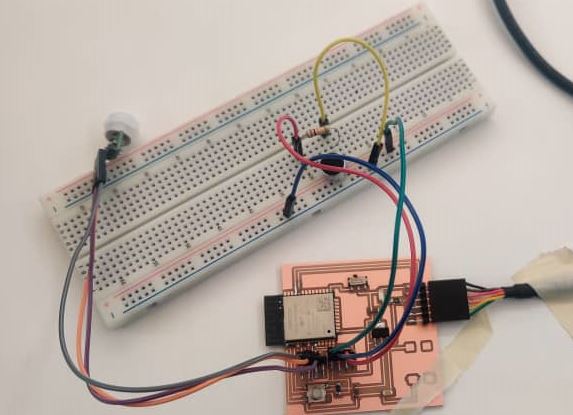
- The connections I made are
- Esp32 Pin 8 to PIR pin 2(OUT)
- Esp32 Pin 12 to Breadboard Resistor(LED end)
- PIR gnd to Board GND
- PIR VCC to Board VCC
- Board VCC to Breadboard VCC
- Board GND to Breadboard GND
- LED GND to Breadboard GND
- After the connections were made, then started coding. To code I took reference from here.and made the changes according to my board.
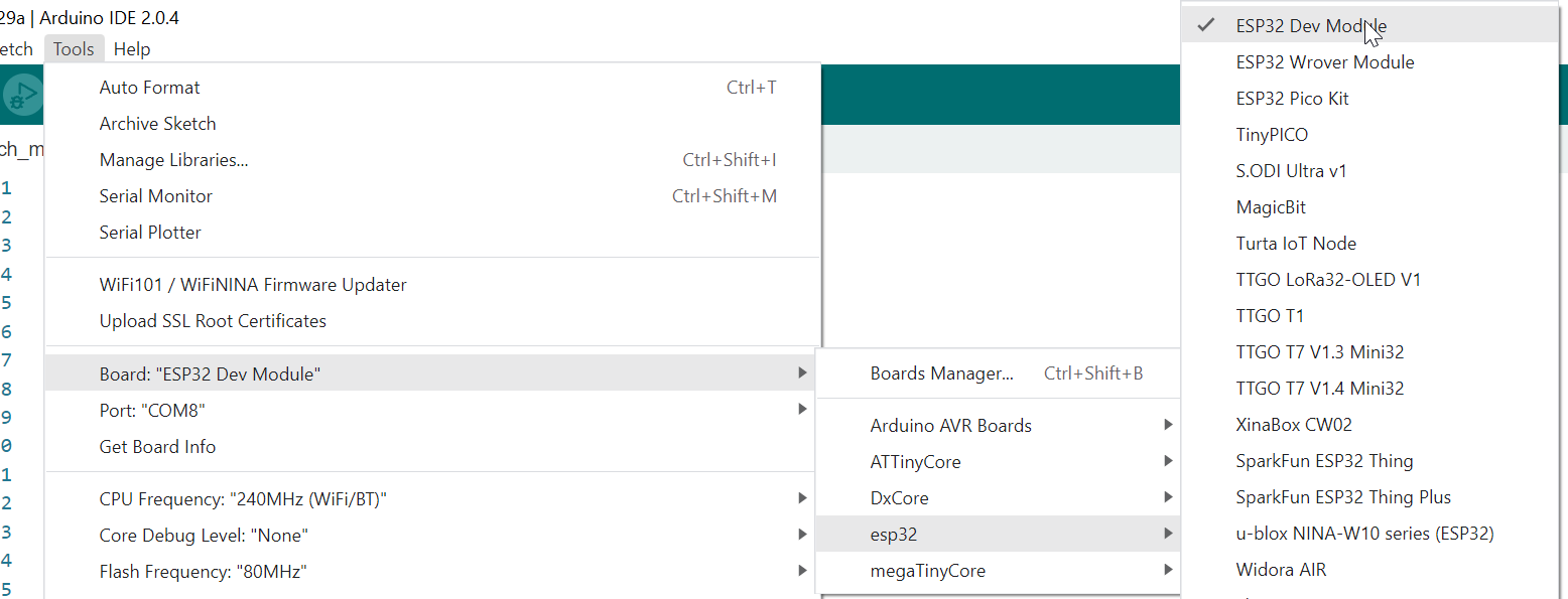
- In Arduino IDE, I selected ESP32 Dev Module as the Board and Port as Com8.
- The code I used.
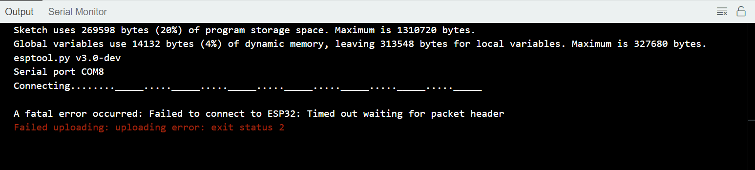
- After compiling, the code got uploaded but I faced with an error which said "Failed to connect to ESP32".
- I couldn't figure out where the problem was so after being frustrated for more than few hours, finally decided to go ATTINY1614 as Microcontroller.
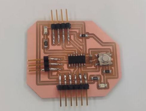
- I used the design of the week 8 board and just added an output pin(4-HeaderPin) and milled the board.
- After milling soldered the components.
    int calibrationTime = 30;

    //the time when the sensor outputs a low impulse
    long unsigned int lowIn;

    //the amount of milliseconds the sensor has to be low
    //before we assume all motion has stopped
    long unsigned int pause = 5000;

    boolean lockLow = true;
    boolean takeLowTime;

    int pirPin = 8;    //the digital pin connected to the PIR sensor's output
    int Buzzer = 12;    //the digital pin connected to the BUZZER output

    /////////////////////////////
    //SETUP
    void setup(){
      Serial.begin(9600);
      pinMode(pirPin, INPUT);
      pinMode(Buzzer, OUTPUT);
      digitalWrite(pirPin, LOW);

      //give the sensor some time to calibrate
      Serial.print("calibrating sensor ");
        for(int i = 0; i < calibrationTime; i++){
          Serial.print(".");
          delay(1000);
          }
        Serial.println(" done");
        Serial.println("SENSOR ACTIVE");
        delay(50);
      }

    ////////////////////////////
    //LOOP
    void loop(){

         if(digitalRead(pirPin) == HIGH){
           tone(Buzzer,500);
           if(lockLow){
             //makes sure we wait for a transition to LOW before any further output is made:
             lockLow = false;
             Serial.println("---");
             Serial.print("motion detected at ");
             Serial.print(millis()/1000);
             Serial.println(" sec");
             delay(50);
             }
             takeLowTime = true;
           }

         if(digitalRead(pirPin) == LOW){
           noTone(Buzzer);
           if(takeLowTime){
            lowIn = millis();          //save the time of the transition from high to LOW
            takeLowTime = false;       //make sure this is only done at the start of a LOW phase
            }
           //if the sensor is low for more than the given pause,
           //we assume that no more motion is going to happen
           if(!lockLow && millis() - lowIn > pause){
               //makes sure this block of code is only executed again after
               //a new motion sequence has been detected
               lockLow = true;
               Serial.print("motion ended at ");      //output
               Serial.print((millis() - pause)/1000);
               Serial.println(" sec");
               delay(50);
               }
           }
      }
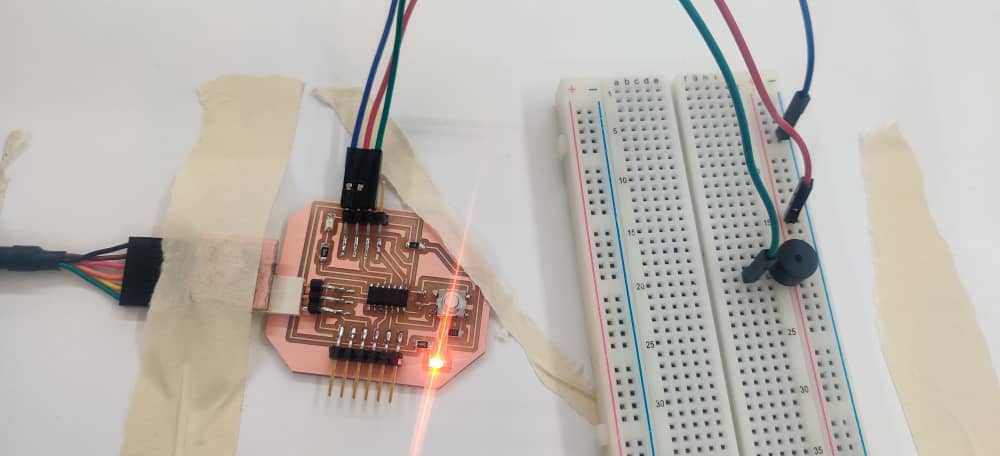
Programming Buzzer as Output with ATTINY1614 as microcontroller(2nd Try)
- I've made the following connections.
- Board Output Pin(Attiny1614 Pin 2) to Buzzer GND on Breadboard
- GND of Output Pin to GND of Breadboard
- VCC of Output Pin to VCC of Breadboard
- I got the code from Here
- Changed the buttonPin and buzzerPin according to my board.
- Compiled and uploaded the code
- Finally it worked. As I click on the button, the buzzer makes sound.
  const int BUTTON_PIN = 10; // Arduino pin connected to button's pin
  const int BUZZER_PIN = 2; // Arduino pin connected to Buzzer's pin

  void setup() {
    Serial.begin(9600);                // initialize serial
    pinMode(BUTTON_PIN, INPUT_PULLUP); // set arduino pin to input pull-up mode
    pinMode(BUZZER_PIN, OUTPUT);       // set arduino pin to output mode
  }

  void loop() {
    int buttonState = digitalRead(BUTTON_PIN); // read new state

    if (buttonState == LOW) {
      Serial.println("The button is being pressed");
      digitalWrite(BUZZER_PIN, HIGH); // turn on
    }
    else
    if (buttonState == HIGH) {
      Serial.println("The button is unpressed");
      digitalWrite(BUZZER_PIN, LOW);  // turn off
    }
  }
