Electronics Production
Task for Week 8
- Group Assignment
- - characterize the design rules for your in-house PCB production process.
- - Extra credit: Send a PCB out to a board house.
- Individual Assignment
- - Make and test the development board that you designed to interact and communicate with an embedded microcontroller.
- - Extra credit: Make it with another process.
Introduction to Electronics(Knowing the Basics)
- Q. What is a Circuit?
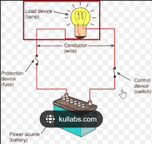
- In electronics, a circuit is a circular path/route that electricity flows through or any fixed path that electricity, data or a signal can travel through.
- For example, in the above diagram, a lamp is connected to a battery through a resistor(R). When the Switch is closed, current will flow through the lamp causing it to emit light.
- Q. What are different power source?
- Electric power sources supply energy to electric systems by moving the electrons in a circuit and hence producing electric current.
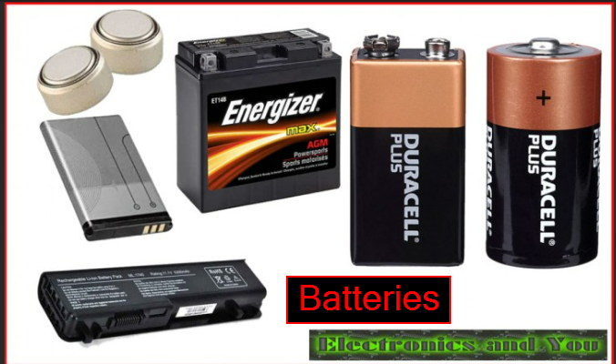
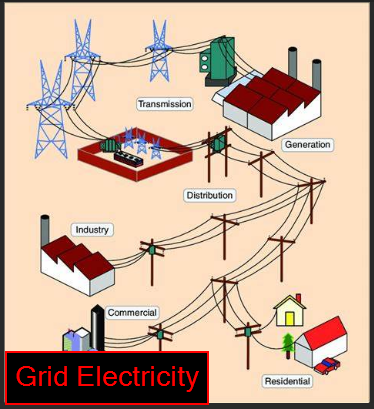
- The most common power sources are 1.Batteries(produces direct current) and 2. Grid(Mains) Electricity which produces Alternating current(AC)
- Q. What is a load?
- Load is a device in the circuit that will draw power. It is normally the largest power draw and most components in the circuit are there to support the load.
- Q. What is a conductor?
- A conductor is something that allows electricity to flow through. Most metals like copper are good conductors.
- Q. What are the difference between voltage, current and resistance?
- Q. What is Ohm's Law?
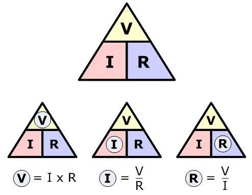
- Ohm's law states that the voltage 'V' across a resistor is directly proportional to the current(I) flowing through the resistor(R)
- Q. What does a resistor do?
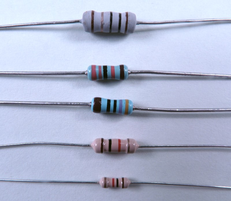
- The primary function of resistor is to "resist" the flow of electrons or it is used to limit and regulate current flow,divide voltages, adjust signal levels,etc.
- Q. What does a capacitor do?
- Capacitor is used to store energy in a electrical field.It doesn't dissipate energy unlike a resistor.
- Q What does a diode do?
- It conducts electric current in only one direction and restricts current from the opposite direction.
- Q. What does LED mean?
- LED stands for Light emitting diode and it is a semiconductor device that emits light when an electric current passes through it.
- Q. What is a regulator?
- A regulator is a device that maintains a constant output voltage irrespective of any kind of fluctuations in the input voltage being applied or any variations in the current drawn by the load.
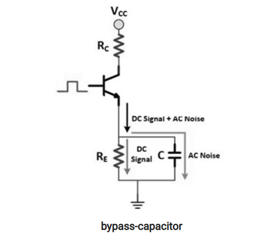
- Q. What is a Bypass capacitor?
- It is a type of capacitor which is used to produce a clean DC(direct current) signal which means that it will short the AC signal to the ground thus producing a proper DC signal.
- Q. What is a Current Limiting Resistor for an LED do?
- Current limiting resistor will reduce the current flow to the LED. LED devices are inherently current-controlled devices and do not respond well to fluctuations in voltage so current limiting resistors is used to ensure safe and stable operation of LED devices.
- Q. How are Capacitors used as High-pass and Low-pass filters? What does it filter?
- The capacitors act as high-pass filters when they pass high frequencies and block DC(Direct current).
- The capacitors act as low-pass filters when they pass DC signals and block AC signals.Instead of placing the capacitor in series with the component, the capacitor will be placed in parallel.
- It filters out AC signals.
- Q. What is VCC?
- VCC stands for Voltage at the Common Collector and in short it is a pin for positive supply voltage.
- Q. What is GND?
- GND is the ground, a common wire for power and signal and it is the pin for negative supply voltage.
- Q. What is Common ground?
- Electronic devices that don't plug into a wall socket have a different type of ground usually called common ground. A circuit that runs on batteries will often use the battery's negative terminal as common ground- a reference point of zero volts compared to the battery's positive terminal.
- Q. What is a ground plane and why is it used?
- A ground plane on a printed circuit board (PCB) is a large area or layer of copper foil connected to the circuit's ground point, usually one terminal of the power supply. It serves as the return path for current from many different components.
Types of circuit
| Open Circuit | Closed Circuit | Short Circuit |
|---|---|---|
| It doesn't provide a closed path for the flow of current. | It can provide a closed path for the flow of current. | It occurs when the positive terminal comes in contact with the negative terminal or the ground. |
| Voltage(V) | Current(I) | Resistance(R) |
|---|---|---|
| Voltage is the amount of potential energy between two points on a circuit. | The continuous movement of electric charge through the conductors of a circuit is called Current. | Resistance is the capability of the resistor to limit the flow of current and reduce the amount of voltage in a circuit. |
| SI unit: Volts(V) | SI unit: Ampere(A) | SI unit: ohms |
Group Assignment
Link to our group assignment is here
Things to Keep in Mind while operating Roland SRM-20
- 1. While changing the end mill, not to screw it too tight since it will tear off the thread which will make it hard to unscrew it.
- 2. To be careful while changing the end mill, the 1/64 end mill is very small, so it might break.
- 3. Always to make the x,y and z zero before cutting to avoid any breakage of the end mill and to avoid destroying the board.
- 4. Changing the sacrificial layer when required.
Individual Assignment
For this week we are asked to make and test the development board that we designed and to make it interact and communicate with an embedded microcontroller. So I decided to mill the design that I made during Week 6.
Converting png to rml
- I had traces and outline of my board in png format. Since the Roland SRM 20 machine reads rml files, I had to convert png to rml files.
- To do so, had to use MODs. Here is the link to go to MIT MODs.
- When you open the MODs, a white blank space will appear.First step is to choose the program, so right clicked on the blank space.
- After that delete the "Websocket device" and make all the x,y and z axis in the SRM-20 milling machine to zero.
- Then beside SRM-20 milling machine, open a module to save the converted rml files.
- After this we can import the png files. First I decided to import the traces of my board. In the read png, click on "select png file" and selected my traces file.
- After importing the traces png file, select the "mill traces(1/64)" in set PCB defaults. This means the traces will be milled using 1/64 end mill.
- Then in the mill raster 2D, click on calculate. This will automatically save the rml file in the downloads and also will show us the toolpath.
- Similarly for Outline of my board, uploaded my outline png file, selected "mill outline(1/32)" in set PCB defaults and Clicked "calculate" in mill raster 2D.


Milling the PCB using Roland SRM-20
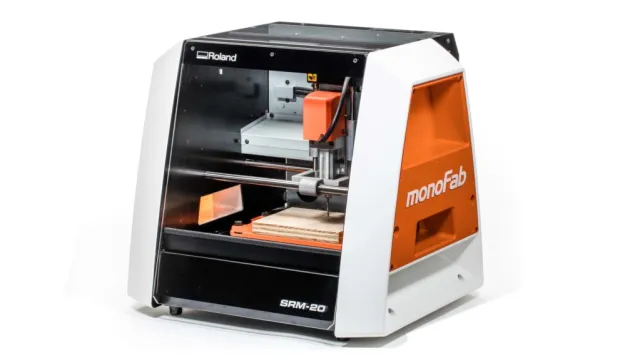
- The Roland SRM-20 is a subtractive rapid prototyping(SRP) milling machine.
- This machine is capable of cutting a wide variety of materials including chemical wood, acrylic, and ABS.
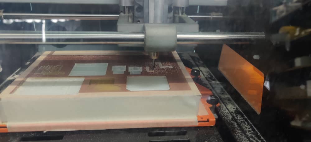
- After having both the rml files saved, need to feed it to the SRM20 machine. For that used the VPanel which is a controller software that can be used to communicate with the SRM20 machine through as USB interface. Following are the steps followed:
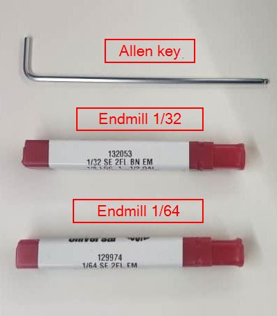
- Tools Required
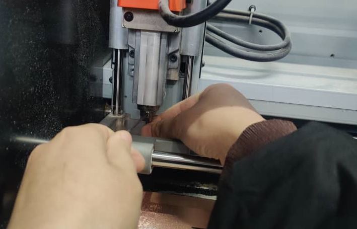
- 1. Changed the end mill to "1/64" for traces. Used "allen key" to loosen and tighten the end mill.
- 2. Set the origin x,y (After changing the endmill, manually set xy position to the desired location and press set xy position on Vpanel).
- 3. To set the z position, lowered the z position till it touches the PCB board. Then loosened the screw and allowed the endmill to drop to the PCB board with gravity. Then set z position on Vpanel.
- 4. After setting x.y and z to zero.Then the machine is ready to mill.So clicked on "cut" in the Vpanel.
- 5. Deleted the already installed file and inserted the trace file of my board.Then to start the milling, clicked on "Output".
- 6. The machine starts milling.
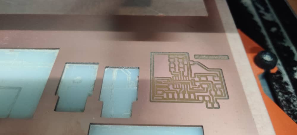
- 7. After the traces are milled, the machine stops. Used the vacuum to clear the dust on the board.
- 8. Then changed the end mill to "1/32". No need to set x and y axis manually. Click on xy to origin. This will bring back the xy to the previously set origin.
- 9. To set the z axis, followed the same procedure as "step 3"
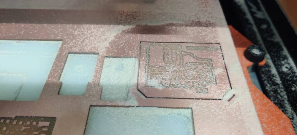
- 10. Then clicked on "cut", selected the "outline file" and clicked on "output". Then the machine starts milling the outline.
- After the machine is done milling, cleared the dust using Vacuum and my PCB was milled successfully.
For Traces


.png)

Things to Keep in Mind while operating Roland SRM-20
- 1. While changing the end mill, not to screw it too tight since it will tear off the thread which will make it hard to unscrew it.
- 2. To be careful while changing the end mill, the 1/64 end mill is very small, so it might break.
- 3. Always to make the x,y and z zero before cutting to avoid any breakage of the end mill and to avoid destroying the board.
Soldering my PCB.
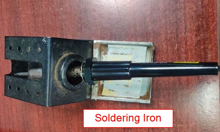
- Soldering is a joining process used to join different types of metals together by melting solder. Solder is a metal alloy usually made of tin and lead which is melted using a hot iron
- The iron is heated to temperatures above 600 degrees fahrenheit which then cools to create a strong electrical bond.
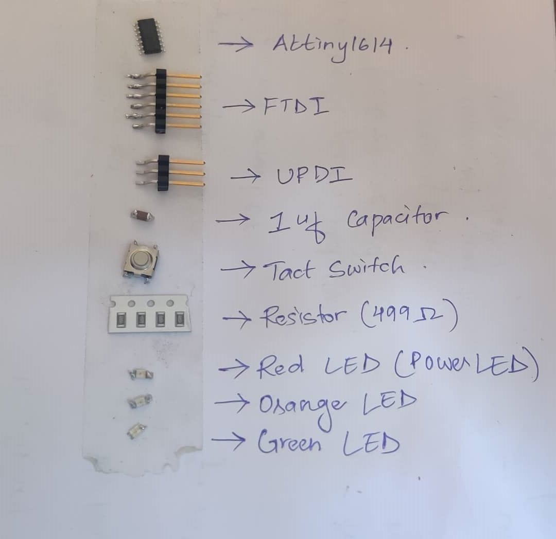
- List of components to solder my PCB board
- Tools used for Soldering
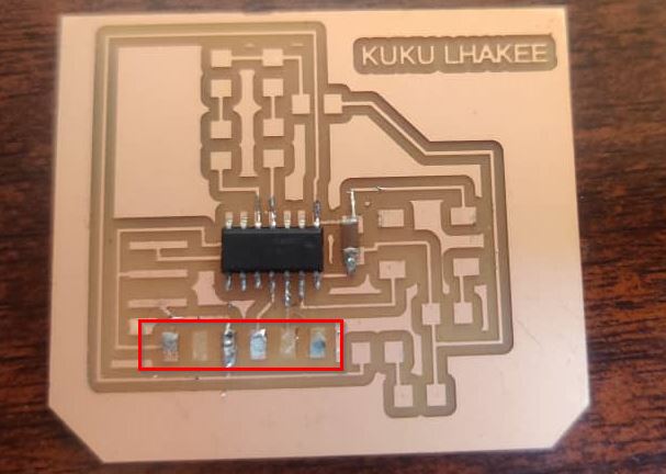
- After identifying all my components and tools, started soldering. I soldered using the traditional method where you place the components with the help of tweezers on the board and solder with a particular rhythm.
- I also made sure not to keep the soldering iron for too long near the components since it could lead to burning the components.
- I had tough time holding the soldering iron since my hands were shaky. Through patience and practice was able to stabilize my hands.
- While soldering the LED made the mistake in identifying the polarity. So I had to do it again. I referred my board design from Eagle for soldering not to repeat the mistake.
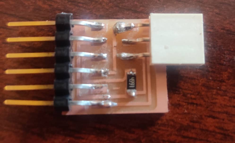
- I was having tough time soldering the FTDI to the board and accidentally while de-soldering, the copper fell out
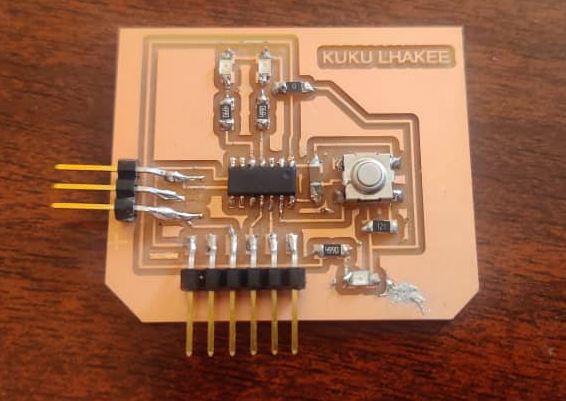
- Had to mill another board. This time I soldered with more patience.Then the soldering was completed.
- After completing the soldering, tested all the connection using the multimeter.
- To program my board, I needed a programmer which I got from here
- Milled the board and soldered it
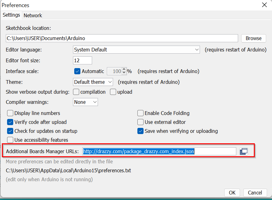
- Since I'm programming the Attiny1614 for the first time had to install the "megatinycore" by Spence Konde from Board manager.But to do so First had to add a url in the preference.If we don't do this, then in board manager, it wont show the "megatinycore".Got the url from Thinley's page.
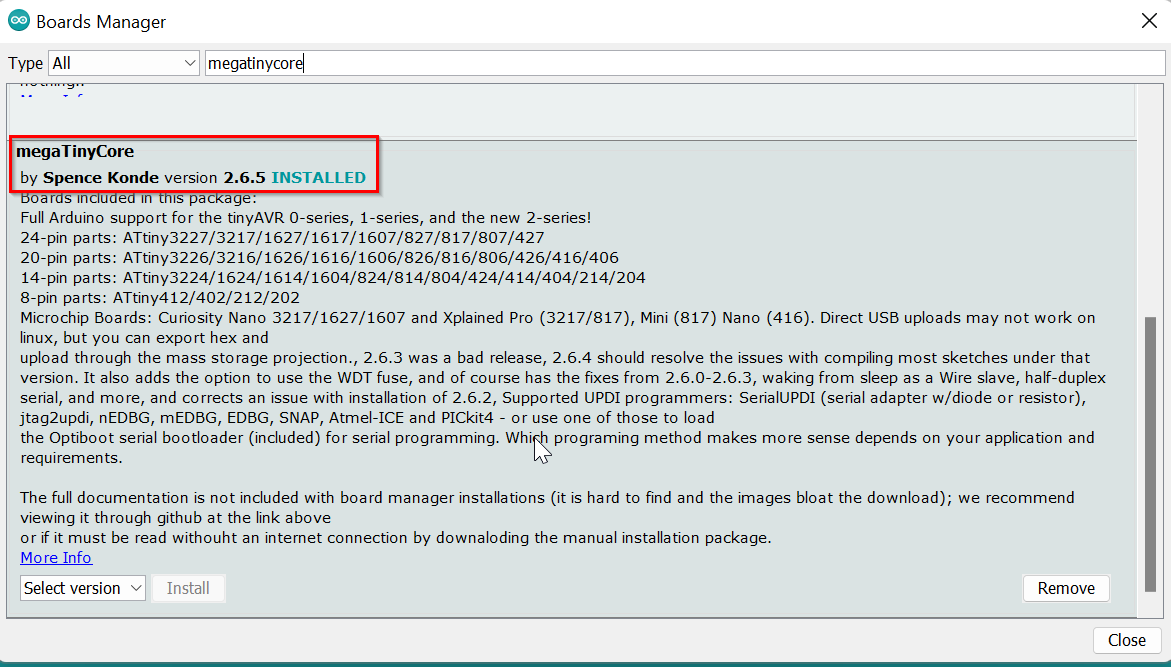
- After that went to Board Manager and installed "megatinycore" by Spence Konde.
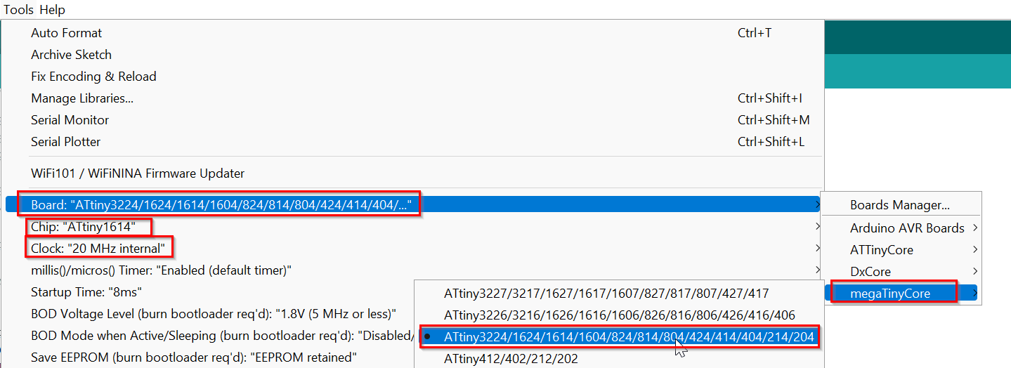
- Then selected the Board, chip, Port and programmer. Asked help from my friends to get this right.
- Sad part was that I wasn't about to upload code to my board.It says that I need a programmer to upload.
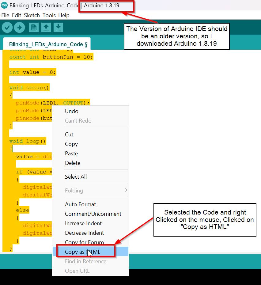
- I asked Thinley about this and he told me to download an older version of Arduino IDE so I downloaded the 1.8.19 version.
- Then I uploaded code in this version of Arduino IDE and the problem now was that it said "UPDI initialization failed error"
- I asked our Guru Zina about this, and found out that I made wrong UPDI connection. I had to flip either the board or the programmer and then make the connection.LOL
- Hence I was able to successfully upload the code and program my board.
- I used the Code from this website.And made the changes according to my design.
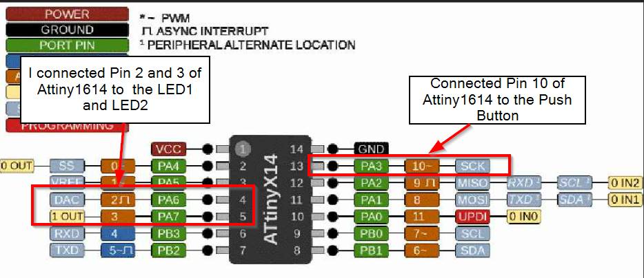
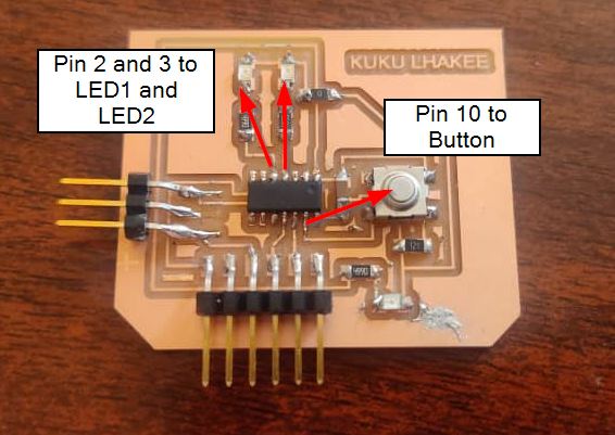
- For LED1 and LED2, I used Attiny1614 Pin 2 and 3 and for Push Button I used Attiny1614 Pin 10.
- Here is a short video of my board communicating with the microcontroller.
- It was fun this week even though came across a lot of challenges. This is the first board designed and programmed by myself. The good news is that it worked fine.
- First you have to select the code that you want to upload to your page.Then right Click on it and there will be an option to Copy it in HTML.Click on that
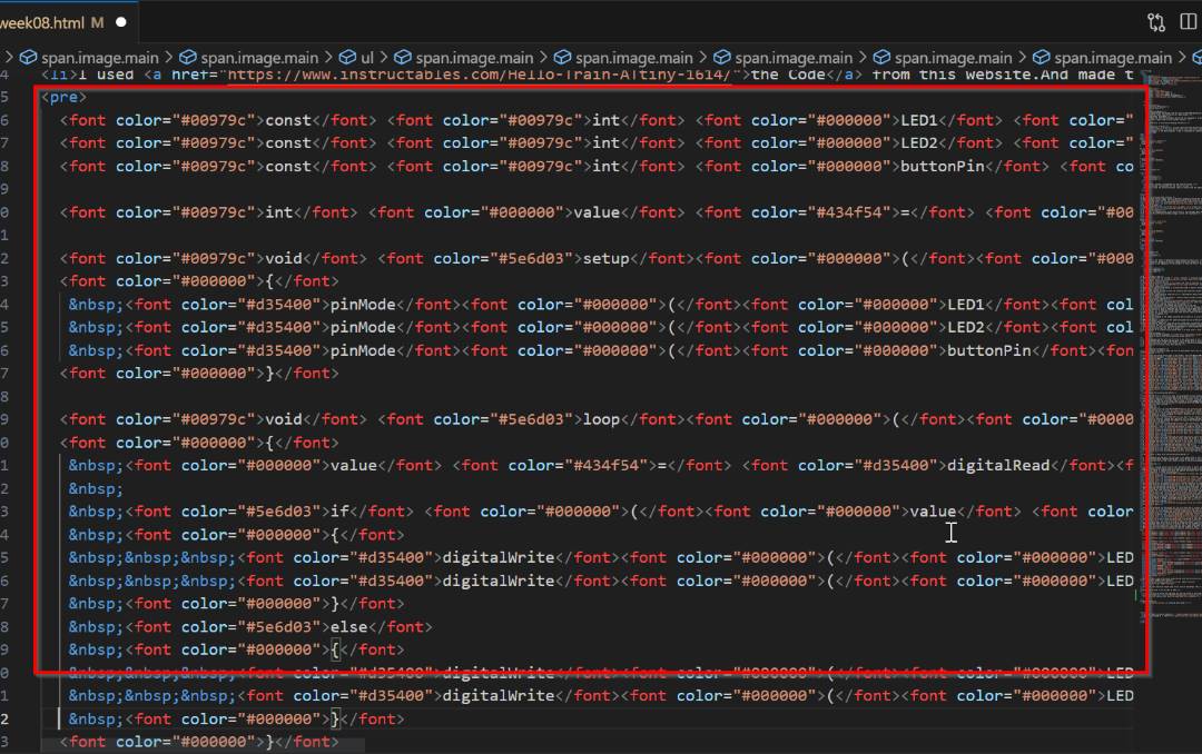
- Then go to VS code and just paste the code where it is required.
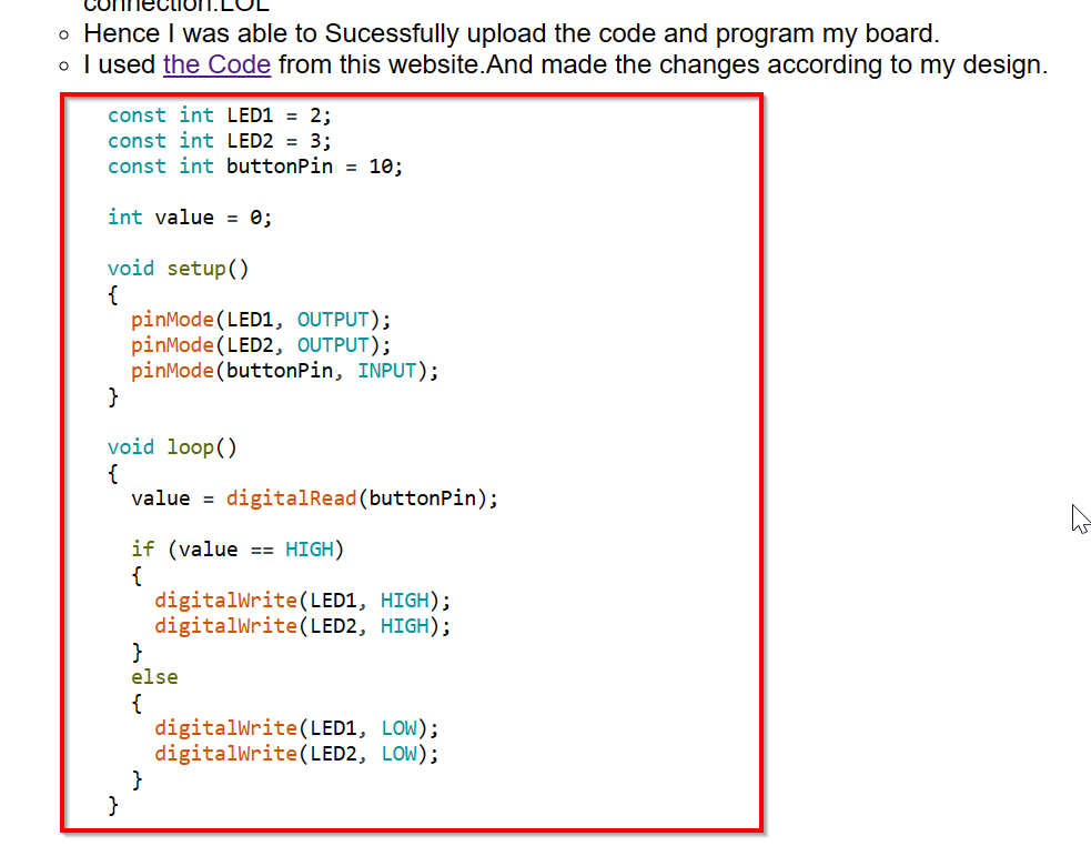
- Here is how the code will look like in your webpage.
- The only thing to keep in mind is that this cannot be done using the latest version of the Arduino IDE. Maybe there could be a way, but I couldn't find it so I downloaded the older version, 1.8.19 to upload my code in Attiny1614 so that version gives you option to copy the code in HTML.
- Blink Code



Programming my Board


  const int LED1 = 2;
  const int LED2 = 3;
  const int buttonPin = 10;

  int value = 0;

  void setup()
  {
    pinMode(LED1, OUTPUT);
    pinMode(LED2, OUTPUT);
    pinMode(buttonPin, INPUT);
  }

  void loop()
  {
    value = digitalRead(buttonPin);

    if (value == HIGH)
    {
      digitalWrite(LED1, HIGH);
      digitalWrite(LED2, HIGH);
    }
    else
    {
      digitalWrite(LED1, LOW);
      digitalWrite(LED2, LOW);
    }
  }
How to Upload code in the VS code as HTML
