Computer-Controlled Cutting
Group Assignment
1. Characterize your laser cutter's focus, power, speed, rate, kerf, joint clearance and types
Individual Assignment
1: Cut something on the vinyl cutter
2: Design, laser cut, and document a parametric construction kit, accounting for the laser cutter kerf, which can be assembled in multiple ways,
Softwares and Machine tools used
| Tools Used | Details | |
|---|---|---|
| Software Tools | ||
| 1: Solidworks | 1. design to calculate the Kerf. 2. The parametric design of the Construction Kit 3. Design of 3D log for Vinyl cutting | |
| 2. InkScape | 1: Editing of 3D logo for Vinyl cutting 2. Editing of Kerf calculation template. | |
| 3. RD Works | 1: Generate the tool path for the Kerf template and construction kit for laser cutting. | |
| 4. Mods Project | 1: To generate the tool path for the vinyl Cutting | |
| Machine Tools | ||
| 1:Laser Cutting Machine: | 1: To generate the tool path for the vinyl Cutting | |
| 2:Vinyl Cutter: | 2: To cut the my interactive 3D logo | |
Laser Cutting Machine
Introduction
The CO2 laser was one of the first gas lasers to be produced. Since its inception in 1964, it has been one of the most widely used lasers. Currently, the highest-power continuous-wave lasers are made of carbon dioxide. A 20 percent efficiency ratio is possible for these devices, which are also fairly powerful. The CO2 laser generates an infrared light beam with the main wavelength bands centred around 9.6 and 10.6 micrometers (μm).
Applications
CO2 lasers used in the industries for cutting, welding and engraving applications. Also used in medical applications for gynecology, dentistry, oral and maxillofacial surgery, and many others.
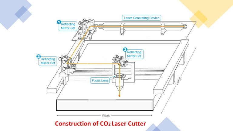
Working Principle
Laser beam is of intense light with a single wavelength. Since this wavelength is in the Infra-Red range of light, it is invisible to the human eye when used with a conventional CO2 laser. The beam passes through the machine's beam path at a diameter of about 3/4 of an inch from the laser resonator, which generates the beam. 3-5 sets of mirrors are used before focusing the light onto the plate. Before striking the plate, the laser beam passes through the nozzle's bore. A pressurized gas, such as Oxygen is also flowing through the nozzle hole.
In the laser cutting head, lens can be used to focus the laser beam. For the focus point to be circular and constant, as well as centred in the nozzle, the beam must be carefully focused. By narrowing the huge beam to a single point, it is possible to get an extremely high level of heat density at that location.
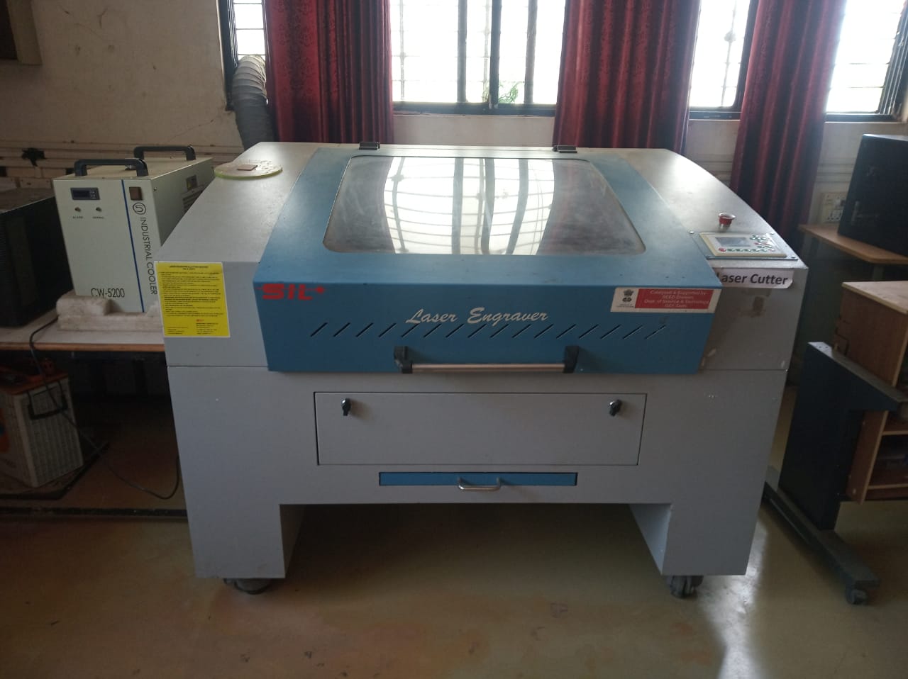
Machine Tool: Laser Cutter
Our lab is having SIL make Laser Cutter. This Laser cutter can cut and engrave wood, MDF, Acrylic, Paper cardboard etc. This can be used to do small furniture items, toys, signage boards, decorative items etc
Specifications
| Specifications | Details |
|---|---|
| Model NO. | 1325-1318 |
| Engraving speed | 0-640000mm/min |
| Cutting speed. | 0-30000mm/min |
| Laser type | Co2 DC glass laser tube |
| Laser power | 80Watt |
| Positioning Accuracy | F80Watt |
| Processing area | 900 x 600mm |
| Power supply | AC 220V+ 5%; 50/60Hz |
| Format supported | AI, BMP, PLT, .DXF, DST etc. |
Safety Measures
Proper training of handling the laser machine start from the main switch- UPS- M/C on-Compressor ON- Program upload -Laser cutting.
Close the m/c door before starting the laser cutting.
Check the compressor and exhaust fan before start of cutting operation.
Stand up 1 feet away from the machine during cutting operation.
Don't open the m/c door immediately after cutting of part. Wait for 2-3 minutes to move out burning gases from the machine cabinet
Check the condenser water temperature and water level
Don't ignore any security alarm during machine operation.
Use laser proof Sunglasses for safety purpose.
Use suitable machine parameters for different materials as per machine Manual.
Group Assignment
Detailed Description of group assignment can be found here
1. Characterize your laser cutter's focus, power, speed, rate, kerf, joint clearance and types
For the group assignment we assigned to find the Kerf and optimum process parameter -Power and cutting speed of MDF(3mm) and Plywood (4mm)
Laser Cutter Kerf: When cutting through, the laser burns away a portion of the material. This is measured in width of material burned away, and is called the laser kerf.
To measure the Kerf and optimum parameter, one template is designed using Solidworks software in which 9 blocks of 30x30 mm dimensions were cut at different speed and power shown in Fig.
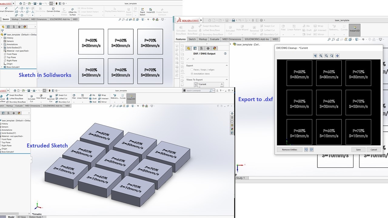
Then, toolpath for CNC laser is generated using RD works software by assigning different power and cutting speed with different color codes. By following safety precautions and following cutting procedure on laser cutter template was cut on the laser cutter
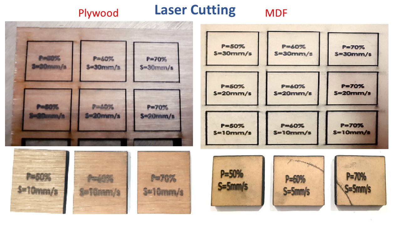
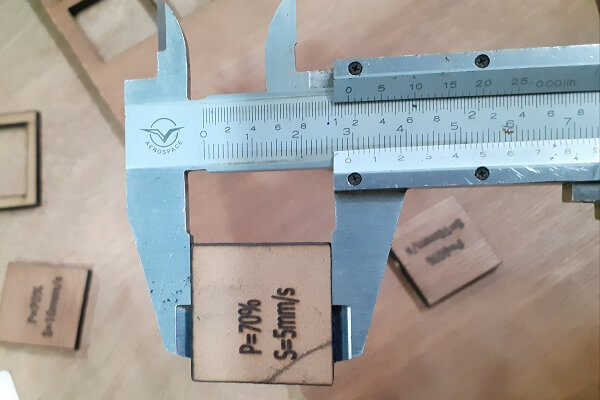
Template cut by laser cutting machine observed carefully. Part which cut from the template, were measure with Vernier calliper to measure the variation in the dimensions. And accordingly we have calculated the Kerf for the MDF and Plywood.
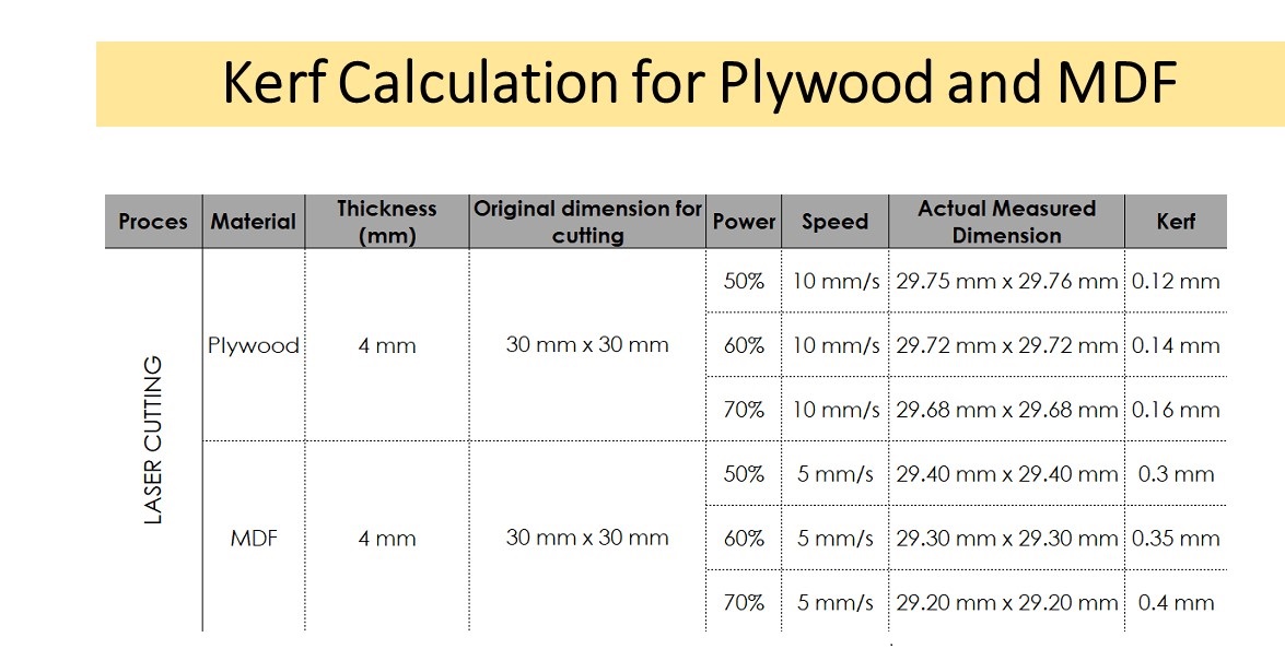
For a 4 mm plywood sheet, optimum parameters are speed 10 mm/s, power between 50% - 70% of 80 watt power. For a 4 mm MDF sheet, cutting speed to 5 mm/s with 50% - 70% of the power for material to cut through.
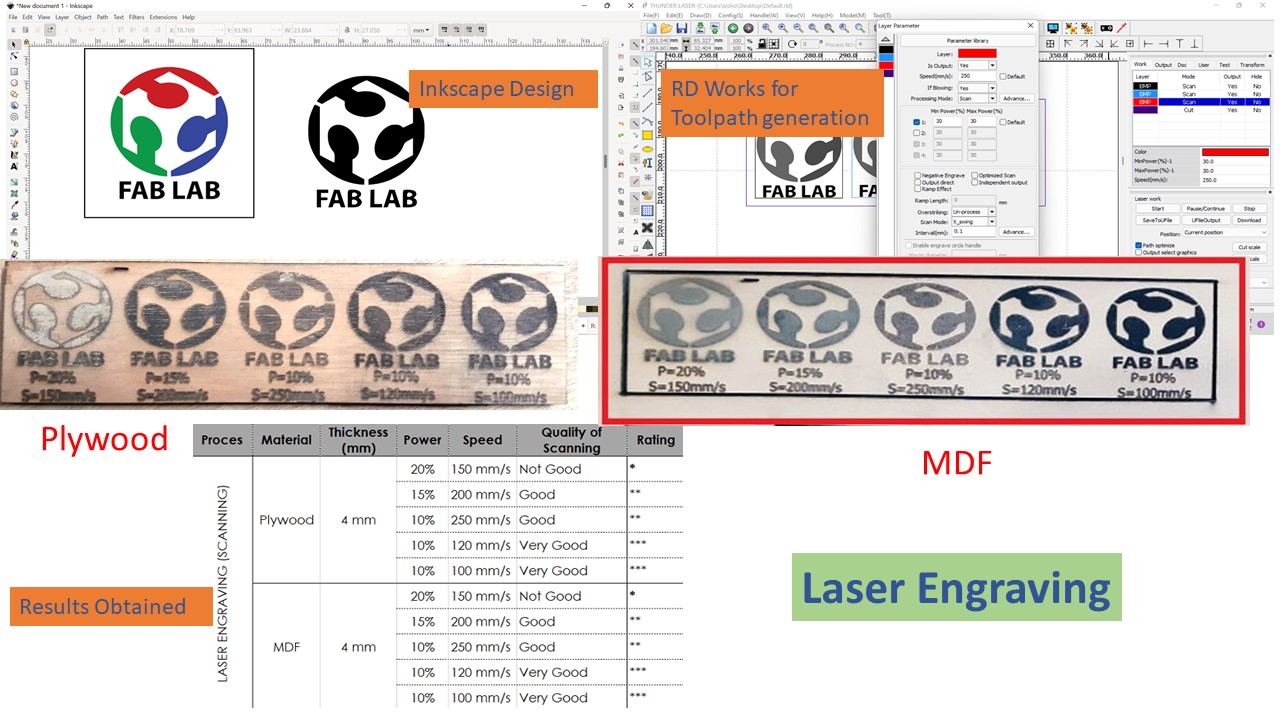
Laser Scanning/ Engraving
For Laser Scanning, we have decided to engrave Fab Lab Logo on plywood and MDF with different speed and Power. We have followed same procedure as laser cutting. And best engraving parameters selected from the appearance of engraving part. We got engrave with a very good quality at 100 - 120 mm/s speed and 10% power.
Optimum Process Parameters for the Laser Cutting
*Power is in % of 80 watt power of laser*
| Laser Cutting | ||||
|---|---|---|---|---|
| Material | Thickness | Power | Speed | Kerf |
| MDF | 4mm | 50-70% | 5 mm/sec | 0.14 mm |
| Plywood | 4mm | 50-70% | 10 mm/sec | 0.3 mm |
| Cardboard | 3mm | 50-70% | 70 mm/sec | 0.15 mm |
| Acrylic | 4.4mm | 55-65% | 5 mm/sec | 0.12mm |
Individual Assignment on Laser Cutting Machine
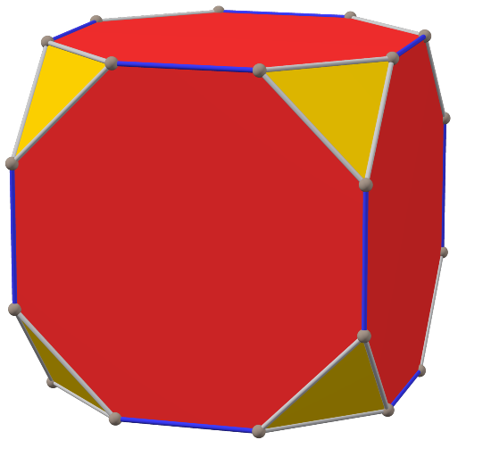
For the construction Kit I have decided to do use geometry of Archimedean solids. In geometry, the truncated cube, or truncated hexahedron, is an Archimedean solid. It has 14 regular faces (6 octagonal and 8 triangular), 36 edges, and 24 vertices.

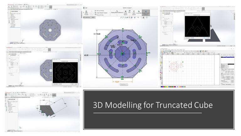
Parametric Modelling
Parametric modeling is one of the critical features used in the 3d modeling cad software to change the shape and size of the object by changing limited dimensions in the model. Most of the standard parts like nut-bolt, gears, chain sprocket, springs, etc., are designed based on parametric modeling. E.g., For Bolt consisting of metric thread, by changing nominal diameter, thread height, and pitch, which are in a relationship with nominal diameter, changes accordingly. We can design the gear for gear by changing the module and the number of teeth or pitch diameter.
Solid modelling of Truncated cube was done in the Solidworks software using parametric Modeling. Material selected for the Assignment is Cardboard of 3mm thickness Accordingly Kerf was considered during parametric Modelling.
Why we need Parametric Modelling for the cutting operations?
In this assignment, we will cut and assemble acrylic, MDF, and Cardboard sheet with press-fit
construction joints. To make the construction with these joints, we need to make slot width
according to the thickness of the sheet. We need to change the slot width accordingly to do the
assembly with different thicknesses. If we have not done parametric modeling, we either need to
change the width of the slot manually or make a whole new design. All modeling software has the
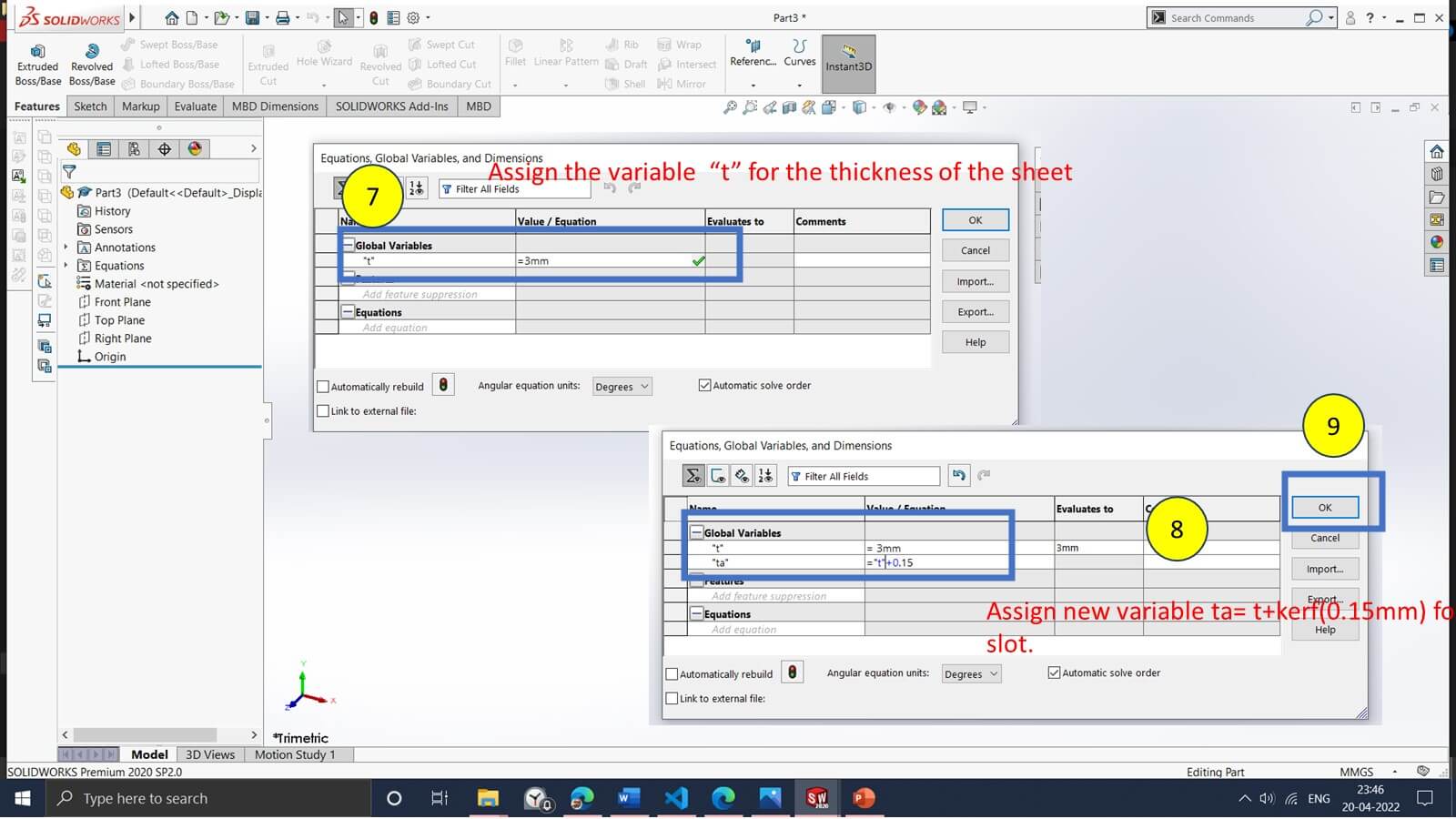
feature of parametric modeling To avoid repetitive work during 3d design. In the parametric
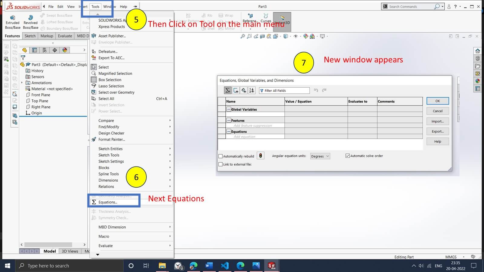
modeling, we need to assign a variable for the width by considering the kerf of cutting and
thickness of the sheet.
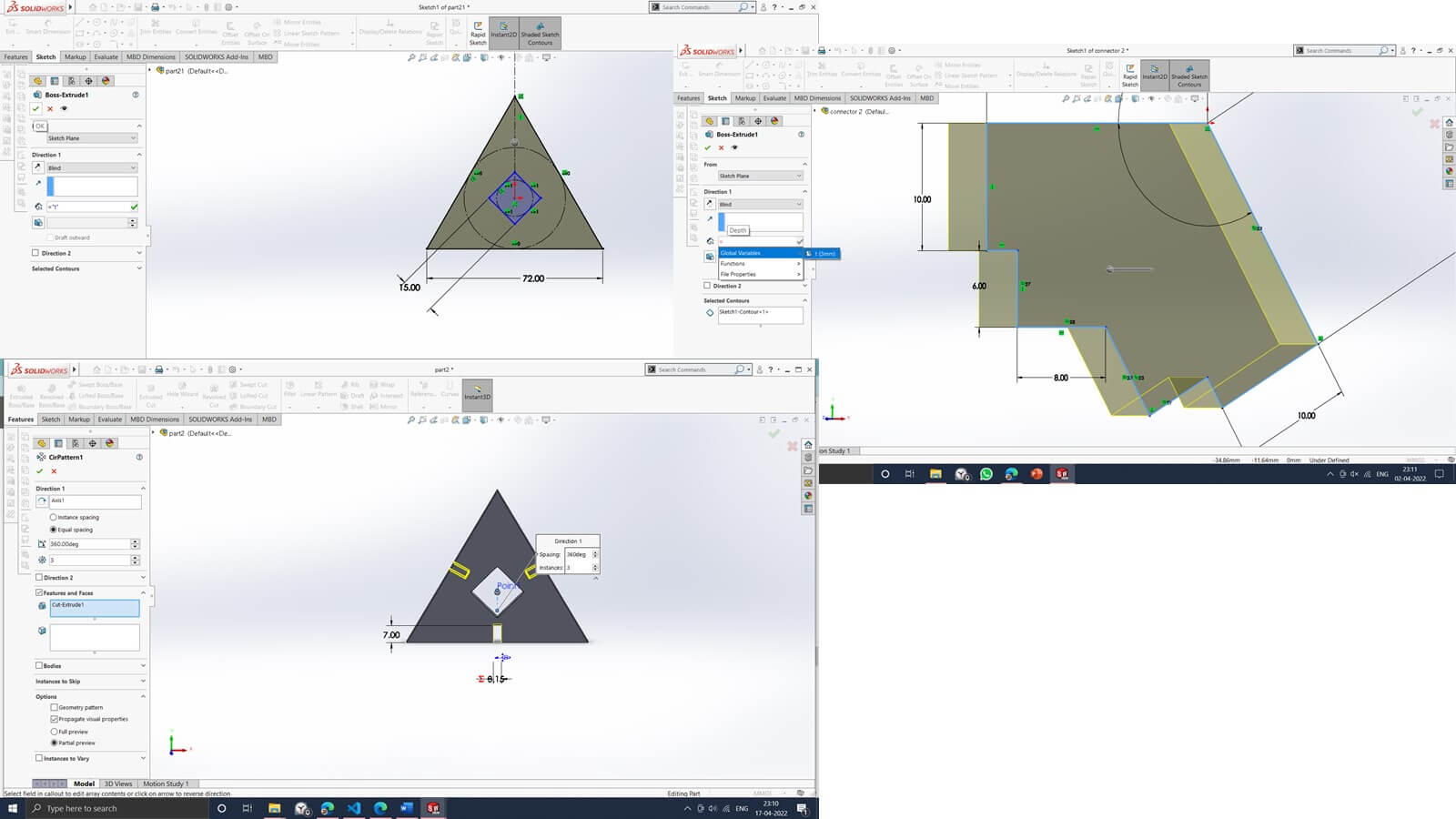
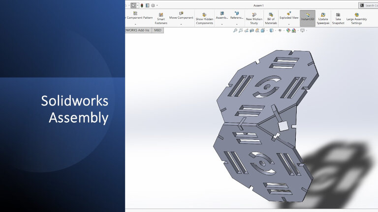
All the parts modelled and assembled in the solidworks software for the best fitting.
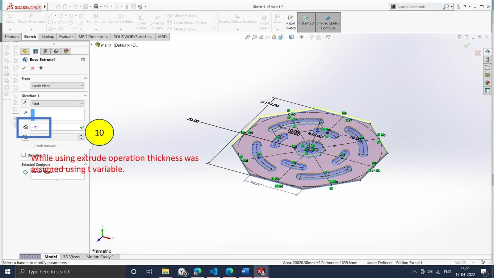
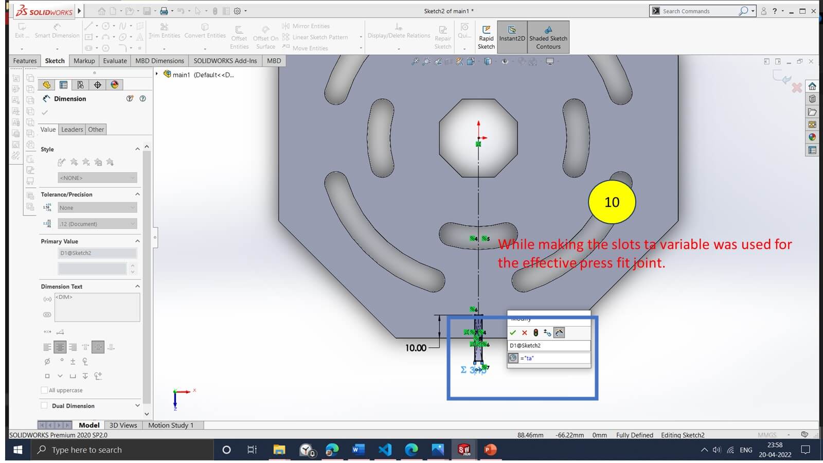
All the parts in the assembly were modeled with parametric modeling for their slots and thicknesses.
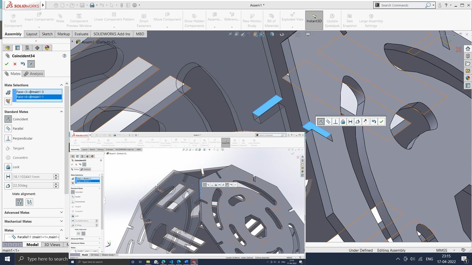
Total Assembly in the solidworks software shown below.
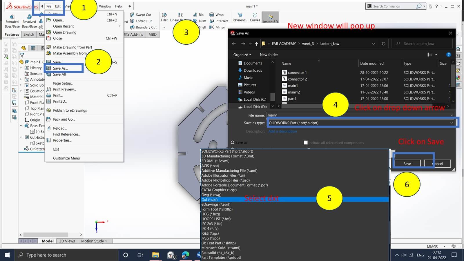
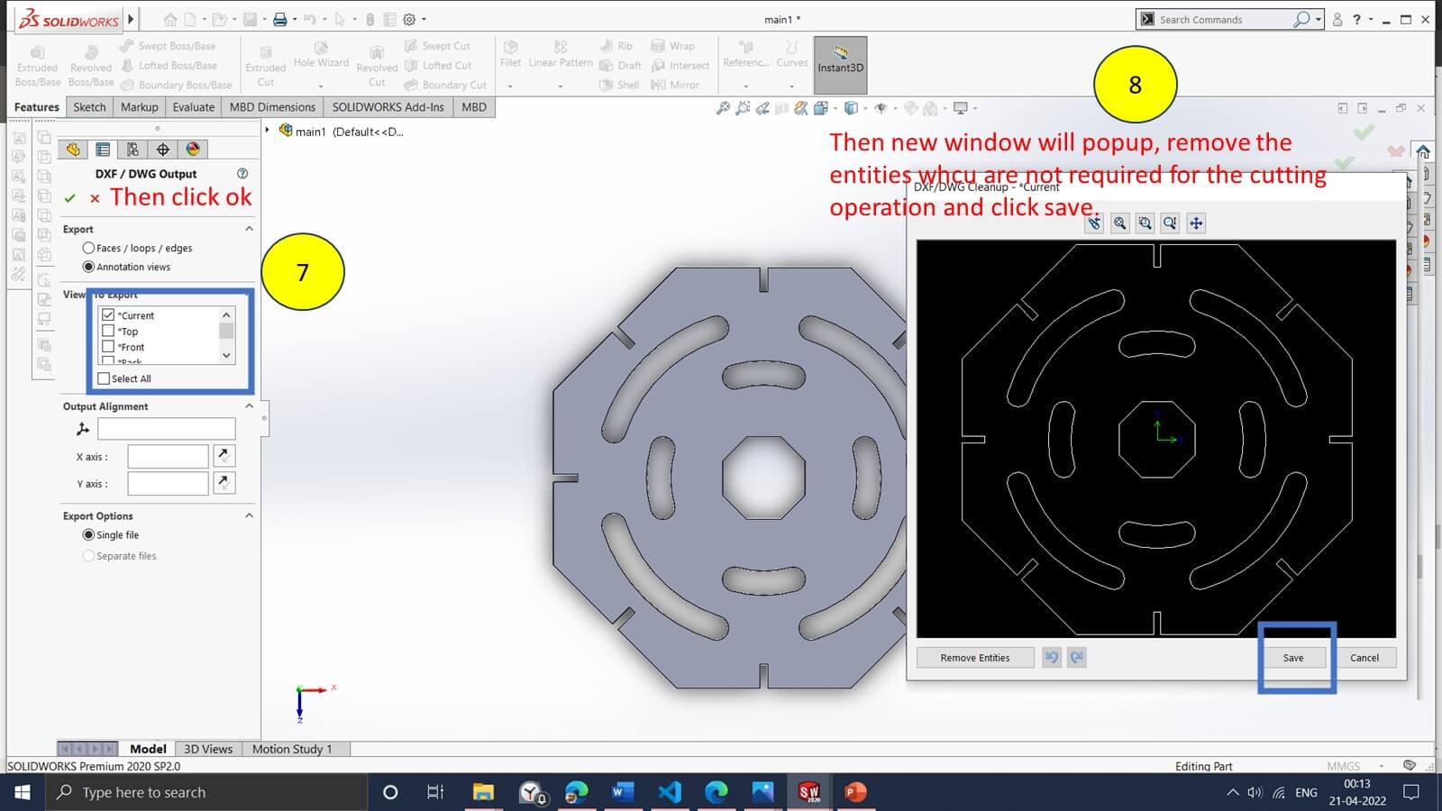
To generate the tool path for the laser machine, we need to convert the 3d file into .dxf format. I have converted the 3d model into .dxf format using the following procedure.
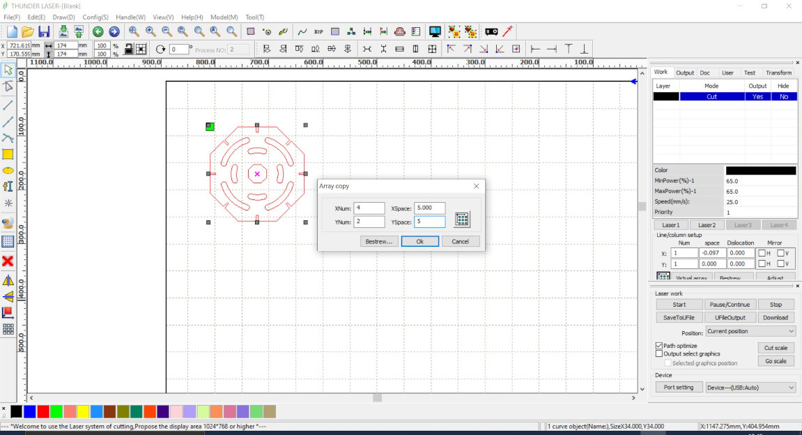
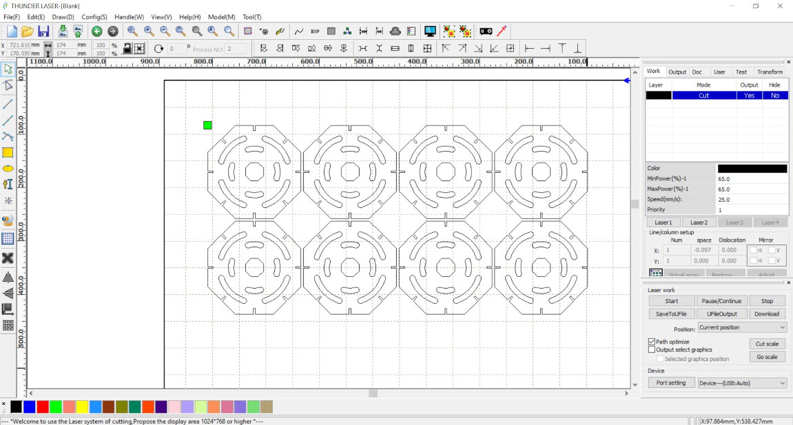
Using RDWorks software pattern of required quanities are made for each of truncated cube and tool path is generated. And Program feed to the Laser Machine.
After Laser cutting I tried to do some different formation using laser cutting parts.
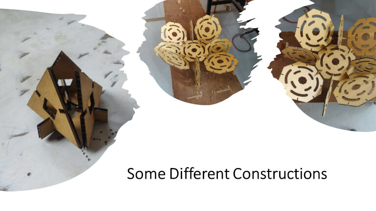
And then I have assembled all the parts to form a Truncated Cube.
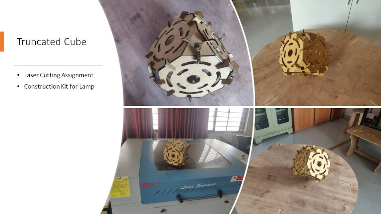
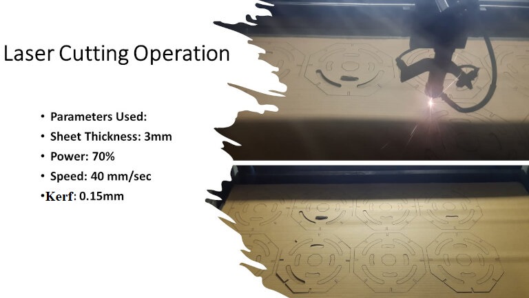
Cutting Video on laser cutting of construction kit.
Vinyl Cutting Machine
Introduction
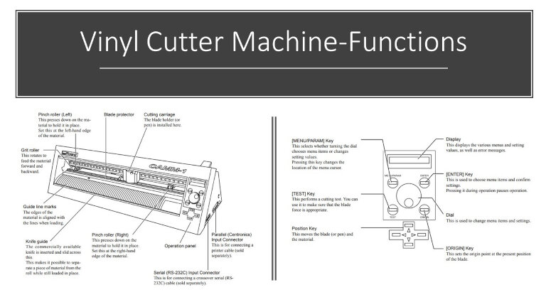
The vinyl cutter cuts the shape of figures into a sheet or piece of vinyl using a little knife. The knife rotates and slides side to side as the vinyl is pushed beneath it. The cut procedure produces an image cut into the material.We have the Roland CAMM Vinyl Cutter.
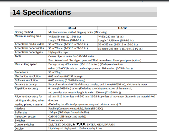
Roland Vinyl Cutter Specifications are:
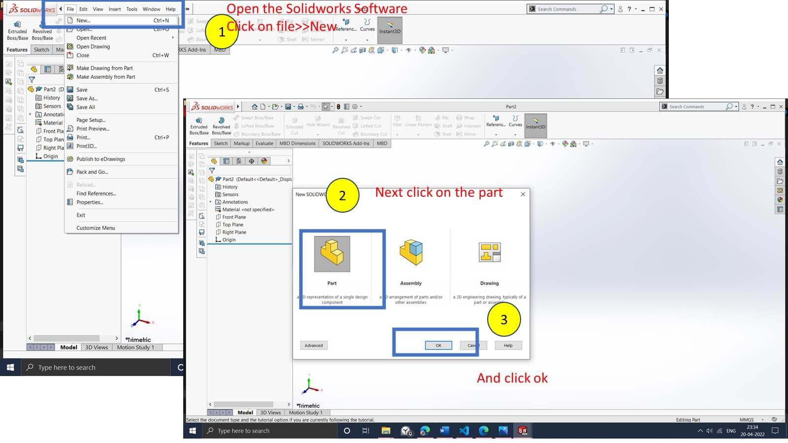
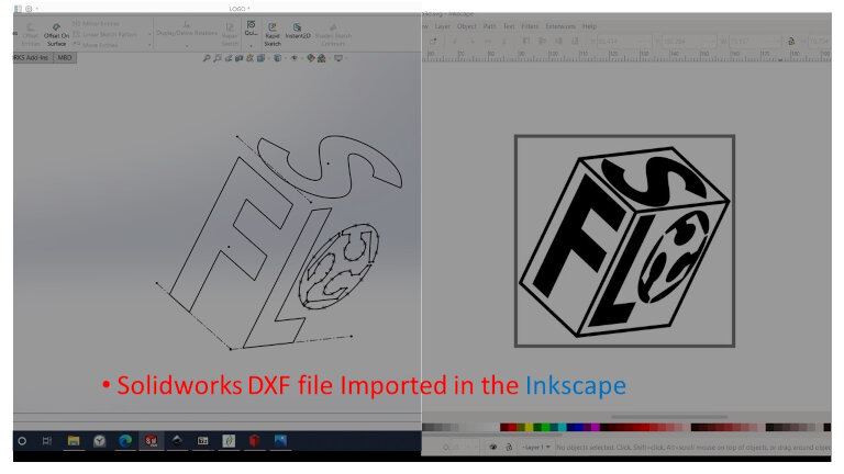
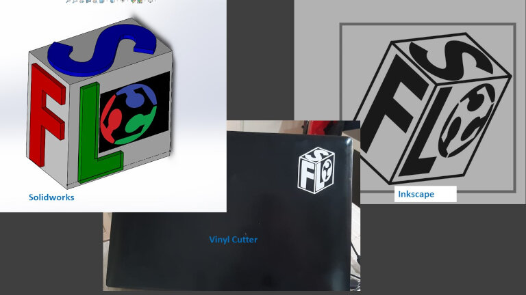
I want to design a 3D logo for our college fab lab. So I started using Solidworks software to create a Logo.
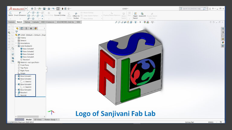
Then Solidworks file is exported in .dxf file and imported in Inkscape software for adding Fab Lab logo and highlighting edges of logo for vinyl cutting.
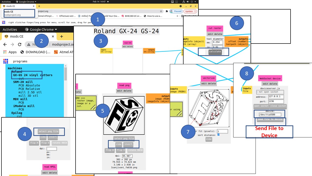
And finally Inkscape file is exported in PNG format and imported in Mods tool to generate the tool path and feed the code to the Vinyl cutting machine.Parameters used for cutting are Force 130 gf and Speed 1cm /sec.
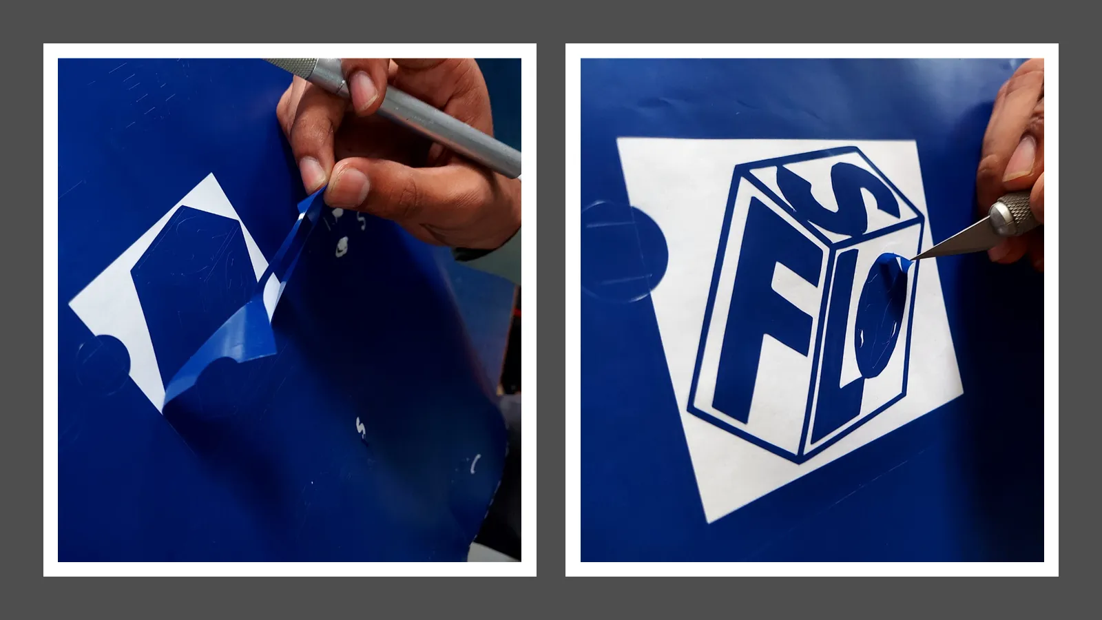
After cutting the logo on the vinyl cutter, unwanted parts are removed from the cutter. Then the required part is transferred to the cello tape.
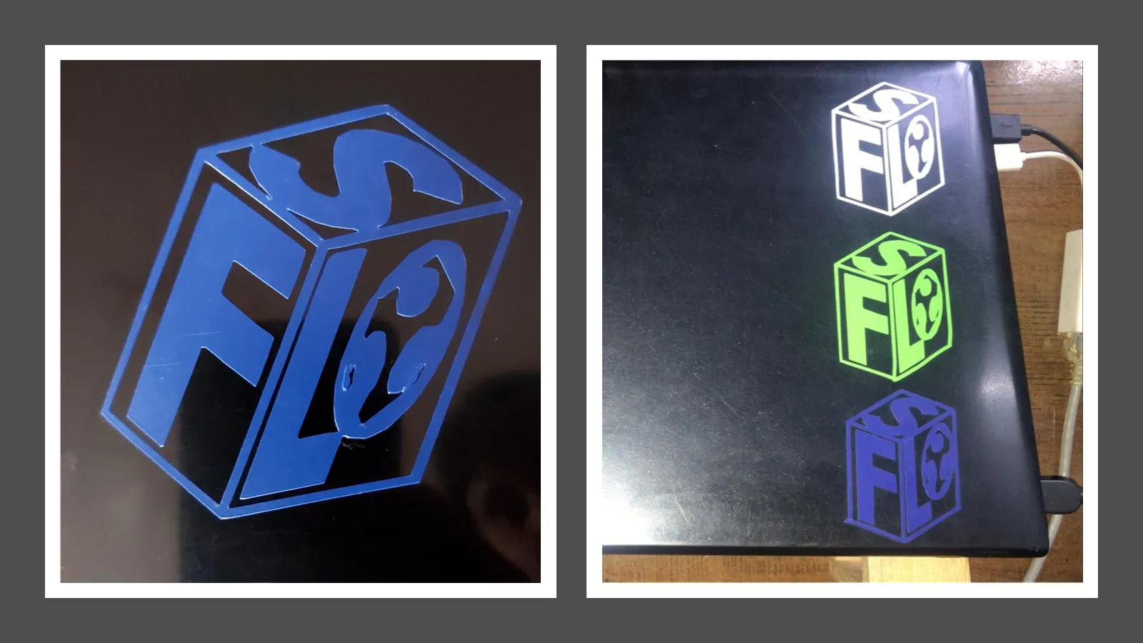
Then the cutting with tape is pasted on the laptop, and gentle pressure is applied to transfer the vinyl cutting on the laptop back.
Then, gently remove the laptop's cello tape and vinyl cutting logo, perfectly placed.
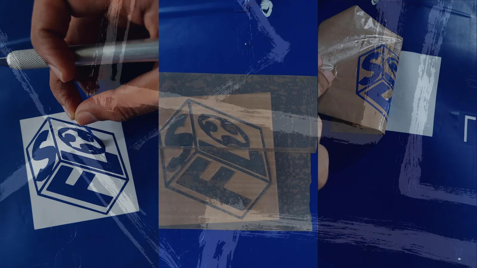
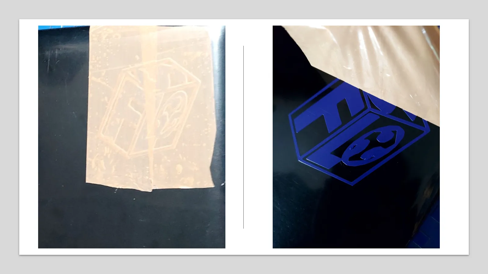
And My 3D Sanjivani Fab Lab logo is ready to paste on my Laptop.
Week Outcomes:
After this week I will able to
1. Find the optimum process parameters and Kerf for different materials on laser cutting machine
2. do parametric modeling of any design
3. Create tool path by selecting proper process parameter for Laser cutter and Vinyl cutter using suitable software.
4. operate Laser cutting machine and Vinyl Cutter with proper safety instructions.
Downloads
3D Modelling .step, .svg and .dxf files can be download here.
Truncated Cube Solidworks files.
Sanjivani Fab Lab Editable Solidworks File.
Sanjivani Fab Lab Solidworks .step File.
Truncated hexahedron assembly .stp file.