Final project
“If you tell me, I will listen. If you show me, I will see. If you let me experience, I will learn!”
— Lao Tzu (6th Century BC)
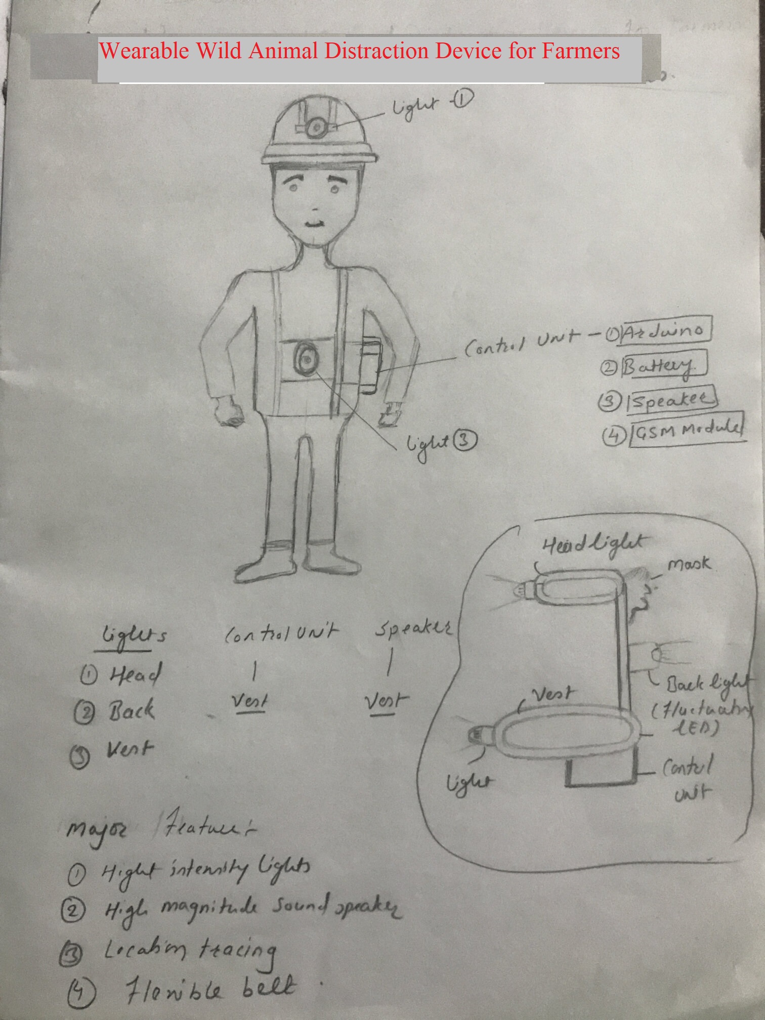
Project Title: Wearable Wild Animals Distraction device
Problem Definition
Due to deforestation, urbanization, and lack of resources, wild animals move out of their natural habitats, searching for food and water. Some villages in India near the forest are majorly impacted because of wandering of wild animals searching for food and water. They are attacking Domestic Animals like goats, cows, etc., for food. In some areas, some people are also attacked by wild animals.
In some rural areas, due to irregular timing of electricity, farmers need to move infield to start water pump and irrigation during the night. There are many chances of a faceoff between wild farmer animals in the night, searching for food, or hiding in the fields. To avoid the attack of wild animals like Wild boar, leopard, hyena, etc., I have thought to use wearable light distraction device which consists of
#Strobing lights mounted on Head, back and on vest zone.
#Mask at the back of head, to avoid attack from back. Tigers attack by biting back of neck, mask with prominent eyes intended to mislead and prevent tiger from attacking from rear.
#LEDs that flash in a random pattern.
#High magnitude sound speaker to create distraction.
This device will not harm any wild animal, intention is to distract them and save the farmers/ people in rural area.
Some Evidences


Some Available Solutions


References
1. Aurangabad-farmer-injured-in-leopard-attack
2. Farmer-injured-in-leopard-attack-near-otur-in-pune-district
3. maharashtra-woman-injured-in-leopard-attack-in-aarey-area-second-attack-in-last-3-days
4. Six-farmers-injured-in-leopard-attack-in-up
5. Farmer-injured-in-leopard-attack
8. Reducing human-wildlife conflict in the blink of a light
Some Jugaad solutions used in rural area
1. In our rural areas, people are using LED powerful LED lights on their bikes or LED torches to
protect themselves from the attack of leopards.
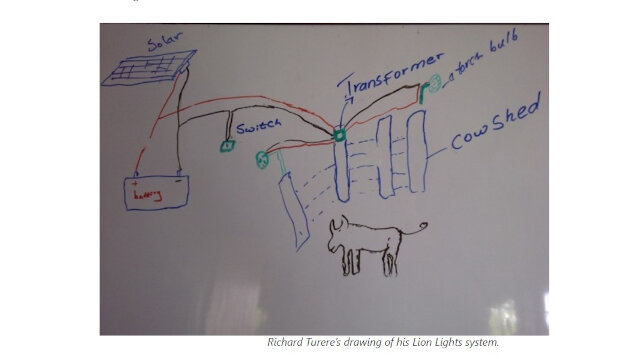
2. Also, we use the Firecracker to move away from the wild animals near our home, farm, and cow
shed.
3. People use the mask with prominent eyes on the back of the head to avoid the attack of an
animal from the back.
Ideation Phase
Ideation Phase :
In some parts of rural India, there is a strong fear of wild animals during the night. Wild animals
attack humans and livestock. Also, some animals like wild boar and elephants destroy crops.
And it is tough to fight with the wild animals because they are in a group.
I want to design a wearable device for the farmers in the rural area who can wear the device
and do their work on the farm at night without any fear of wild animals.
A farmer can wear this device very quickly and use it very effectively.
From the previous literature, it was observed that strobe lights and loud sounds distract wild
animals,
Some researchers have designed a system that consists of proximity sensors to detect the
movement of wild animals near the farm, and lights that start with a strobing effect.
The current limitation of the existing system:
Existing systems are needed to be installed in the farm field. The system has limitations in
covering all the farm fields. And it is challenging for all the farmers to install this system.
Proximity sensors used in the devices have a limited range. An animal may hide in other parts of the
field and attack the Farmer.
There are chances of fae off between the animal and the Farmer outside the farm, like a typical
road, near a house, etc.
So I want to design a wearable device for the farmer. By using it, farmers can freely work in the
field at night with
Full bright light for the visibility at night with strobing effect during an emergency
Motion sensor: Wild animals usually attack humans from the backside, so I want to add a motion
sensor to my device to detect animals from the back and give some signals to make the person aware
of the existence of some live animals from the back.
When the Farmer feels there is anything near him, he can press the emergency button, which
generates a loud firecracker sound to move away from the wild animal from the user.
Safety Jacket
The selection of a safety jacket is the preliminary task in the project. Once I finalize it, I will
design the electronics and the remaining stuff. Initially, I decided to buy stretchable fabric and
sew customized safety wearables.
In the initial phase, I searched for safety jackets for applications like military, mining,
construction, road safety, sports, etc.
In the initial phase, I searched for safety jackets for applications like military, mining,
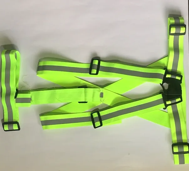
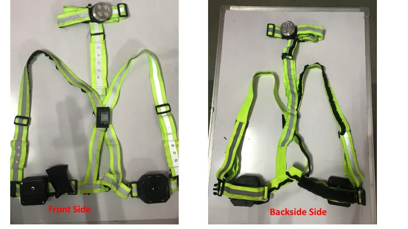
construction, road safety, sports, etc. For the wearable device, I searched for safety jackets,
airheads, life jackets, or ramp jackets that I could use for my project. After a long search in the
market, I learned about Reflective Jacket for Cycling and Running, which consists of a Reflective
Vest Belt Stripe for Night Safety. The jacket will also be helpful for Construction, Traffic,
Cycling, Ramp Vests, and High Visibility and is suitable for Men and Women.
High-visibility clothing consists of any extremely luminous fabric in its inherent matte quality or
color, making it easily distinguishable against any background.
As personal protection equipment, high-visibility clothing is worn to increase a person's visibility
and prevent accidents caused by others who are not visible. Consequently, it is frequently worn in
vocations where hazardous situations are produced by moving vehicles or dim lighting. These
positions include railroad and highway employees, airport personnel, and emergency services
personnel. Cyclists and motorcyclists may also wear high-visibility clothes to boost their
visibility in motor vehicle traffic.
Wikipedia-High-visibility_clothing
Processes and Systems ued for the Final Project
| Processes used in Final Project | ||
|---|---|---|
| Processes | Details | |
| Computer Aided Design | Tools: Solidworks Software -Design of Project prototype, casings for controller board,Speaker and Sensor. | |
| Computer Controlled Cutting | Software Tool- Laser Cad, Machine used: SIL Laser cutter-Laser Cutting of fabric for LED stitching | |
| Electronics Production | Tool: Mods Project, Machine : SRM 20-PCB Milling of Main board, Mosfet board and LED board | |
| Electronics Design | Tool: Eagle PCB Design of Main Project board, Mosfet and Headlight LED board | |
| 3D Scanning and Printing | Tool- Prusa Slicer-3D Printing of the Casings of Main microcontroller Board, Sensor and Speaker. | |
| Embedded Programming | Tool: Arduino IDE-Programming of Project PCB board using Arduino IDE. | |
| Input Devices | Motion Sensor to detect motion of Wild animals and and Emergency switch to start Speaker with Firecracker sound and Strobing Light Effect. | |
| Output Devices | LED light for the Night visibility and Strobing light effect to distract Wild Animal and Speaker to produce firecracker sound. | |
Bill of materials for Wearable device:
- Reflective Safety Belt: 180rs
- Radar Sensor: 90rs
- 4 Watt Speaker: 90rs
- MP3 Decoding Board: 140rs
- ESP 32 : 350rs
- SMD Dome Shaped LED (10 nos.): 150rs
- Through hole 5mm LED (4 nos.): 60rs
- Lipo Battery 7.4 Volt : 750rs
- Other Miscellaneous : 200rs
- Total: 2010rs ($ 25)
3D Modelling
With a preliminary project sketch, I have designed the final sketch with the Solidworks software. Basic features like extrude, revolve, sweep, hole, and fillet are used to design the parts . Different mating features are used in the part assembly. Then I rendered the part for a better visualization of the device. I downloaded the 3D human model from the GrabCad internet repository. All the belt modeling is done using the Sweep feature. Enclosure for the Microcontroller, Speaker casing, and Sensor casing are done using Solidworks software.
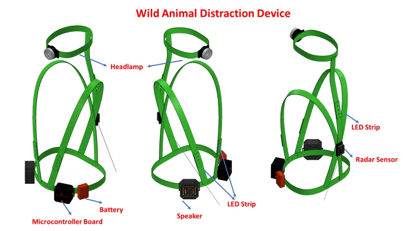
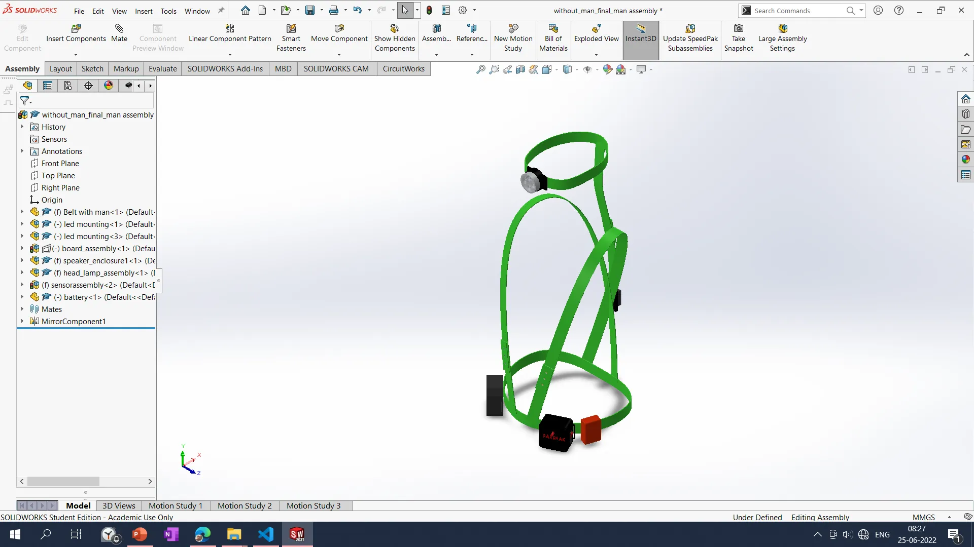
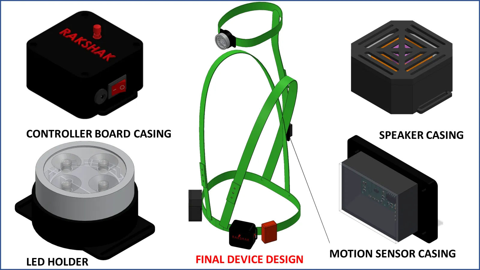
The final design of the wearable device created using Solidworks
software is shown below. The design consists of an adjustable safety jacket, a microcontroller
casing, a speaker casing, woven LEDs, and a headlamp.
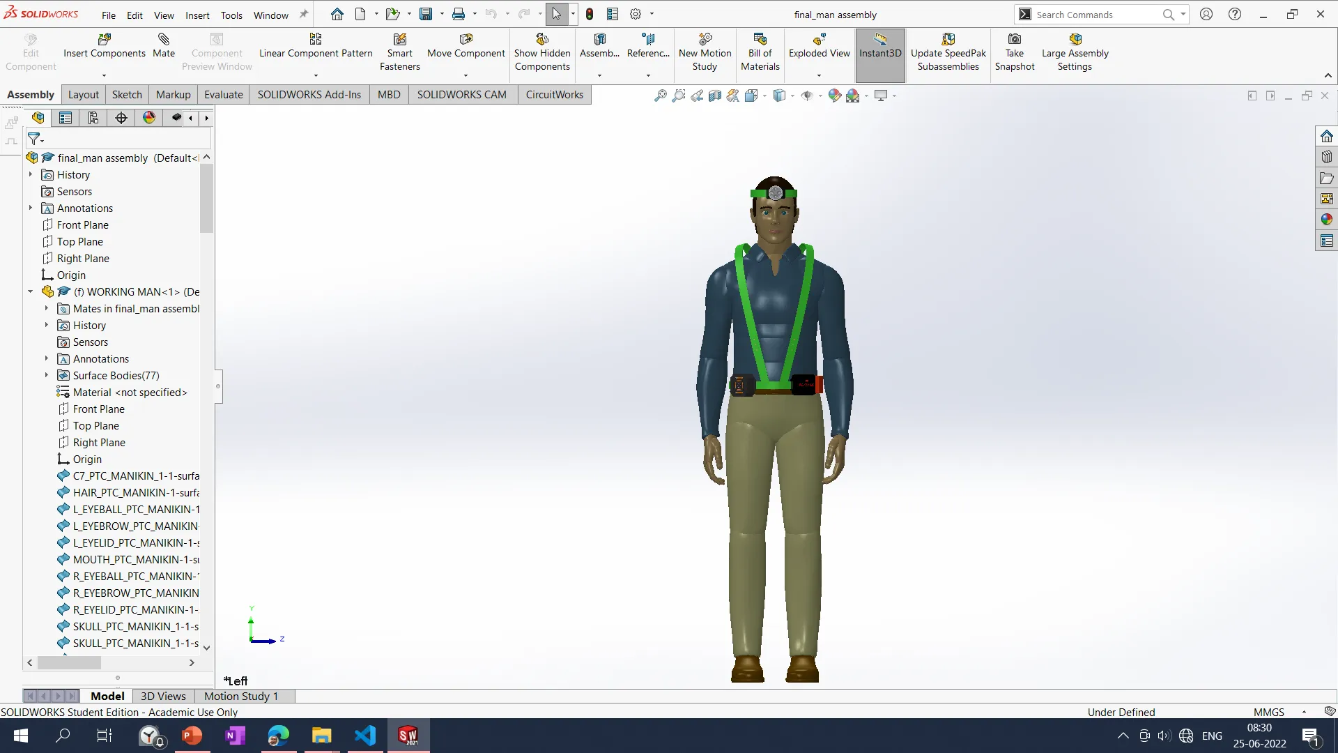
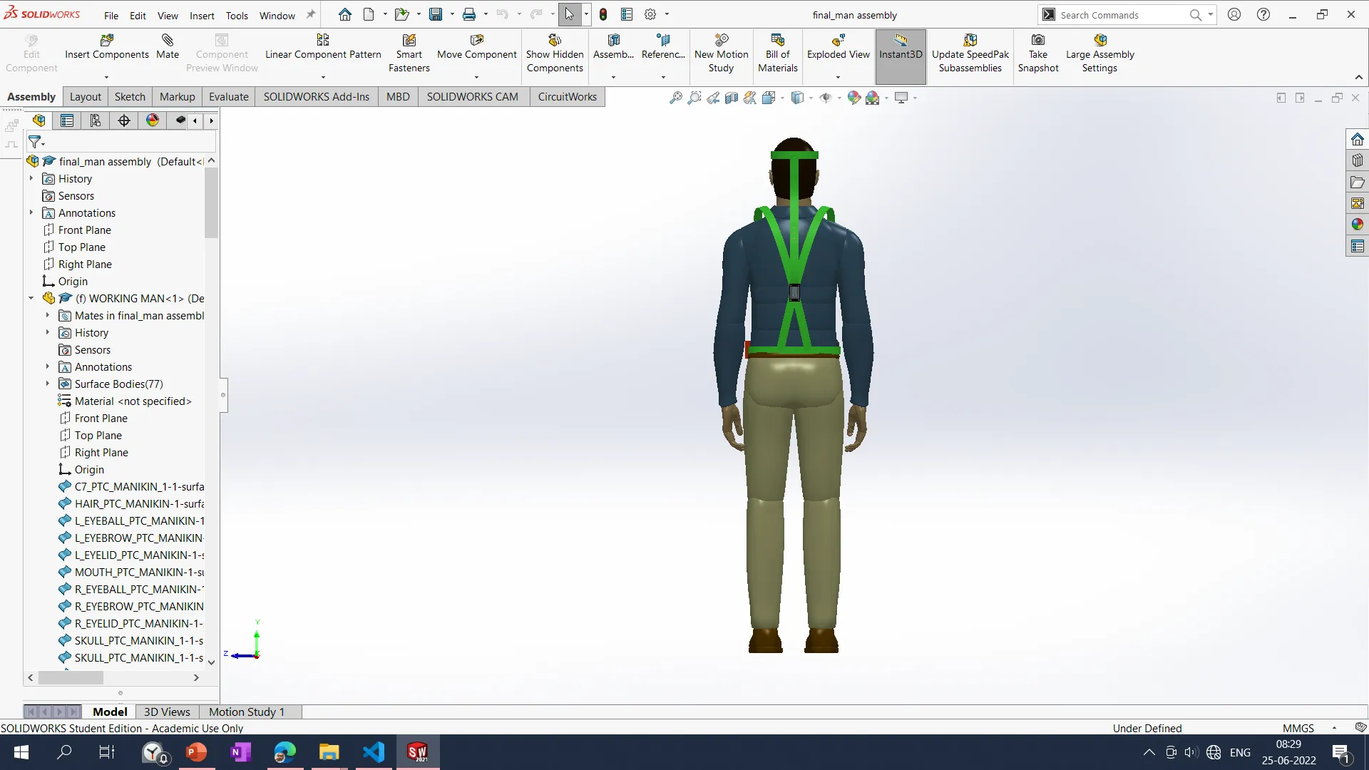
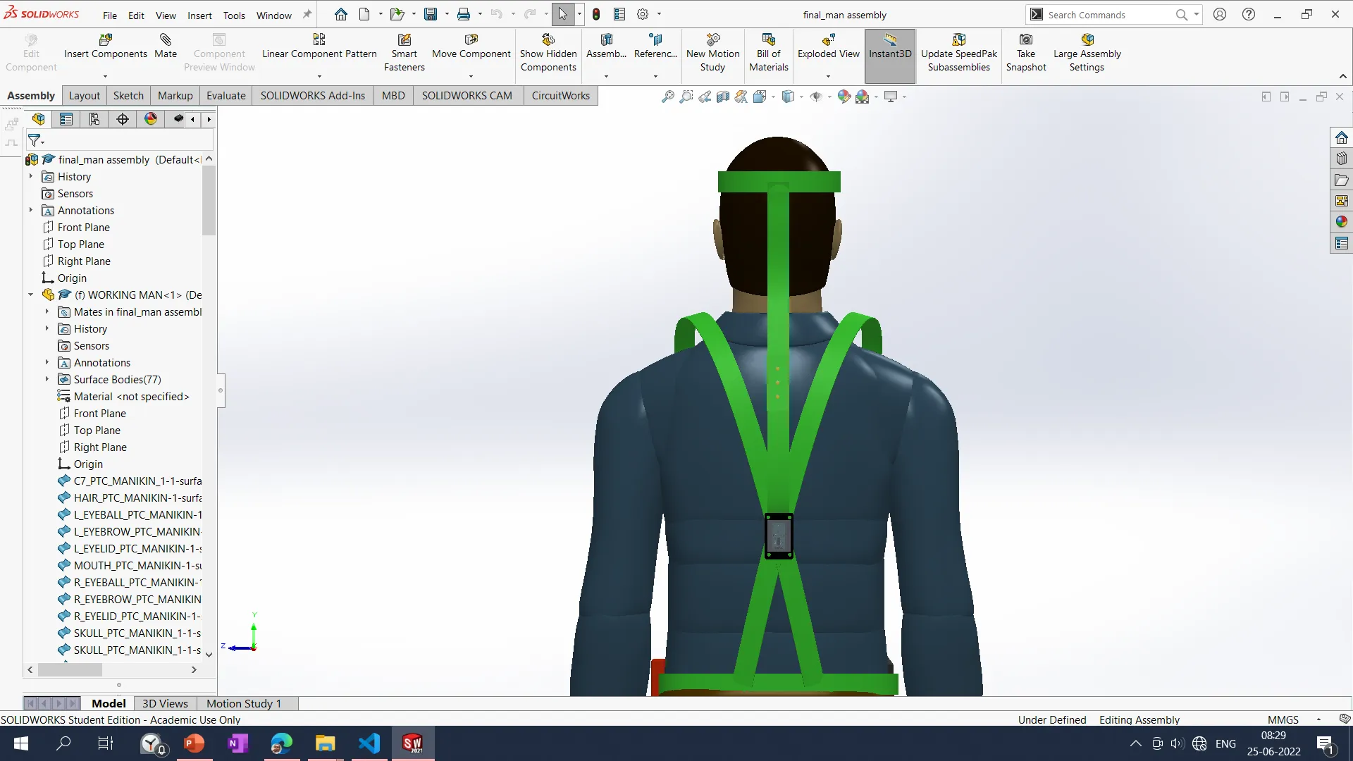
All the details of a man wearing a distraction device with front and back views are shown below. This helps me to better understand the device from an aesthetic and ergonomics point of view.
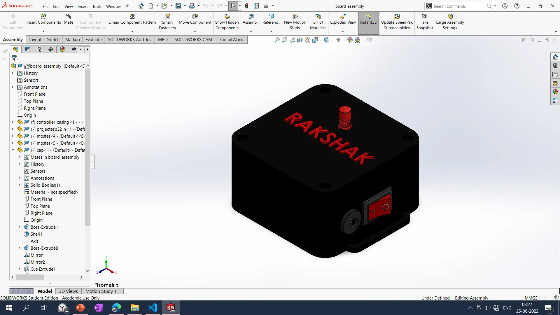
After designing the microcontroller and the MOSFET board, I designed the casing for it by taking their dimensions. I have imported the 3D design of the microcontroller board and the MOSFET board to assemble them in the SOLIDWORKS software to assemble them with the actual dimensions shown in the animation below. The casing for the controller board is shown below. The controller casing consists of the main microcontroller board, 2 MOSFETs, an On-OFF switch, an emergency switch, and a Power jack. All the parts are designed as per the standard specifications. The project's final design is as shown below: a Flexible belt jacket with a Microcontroller casing, Speaker casing, Led Strips on the front and backside, and a headlight.
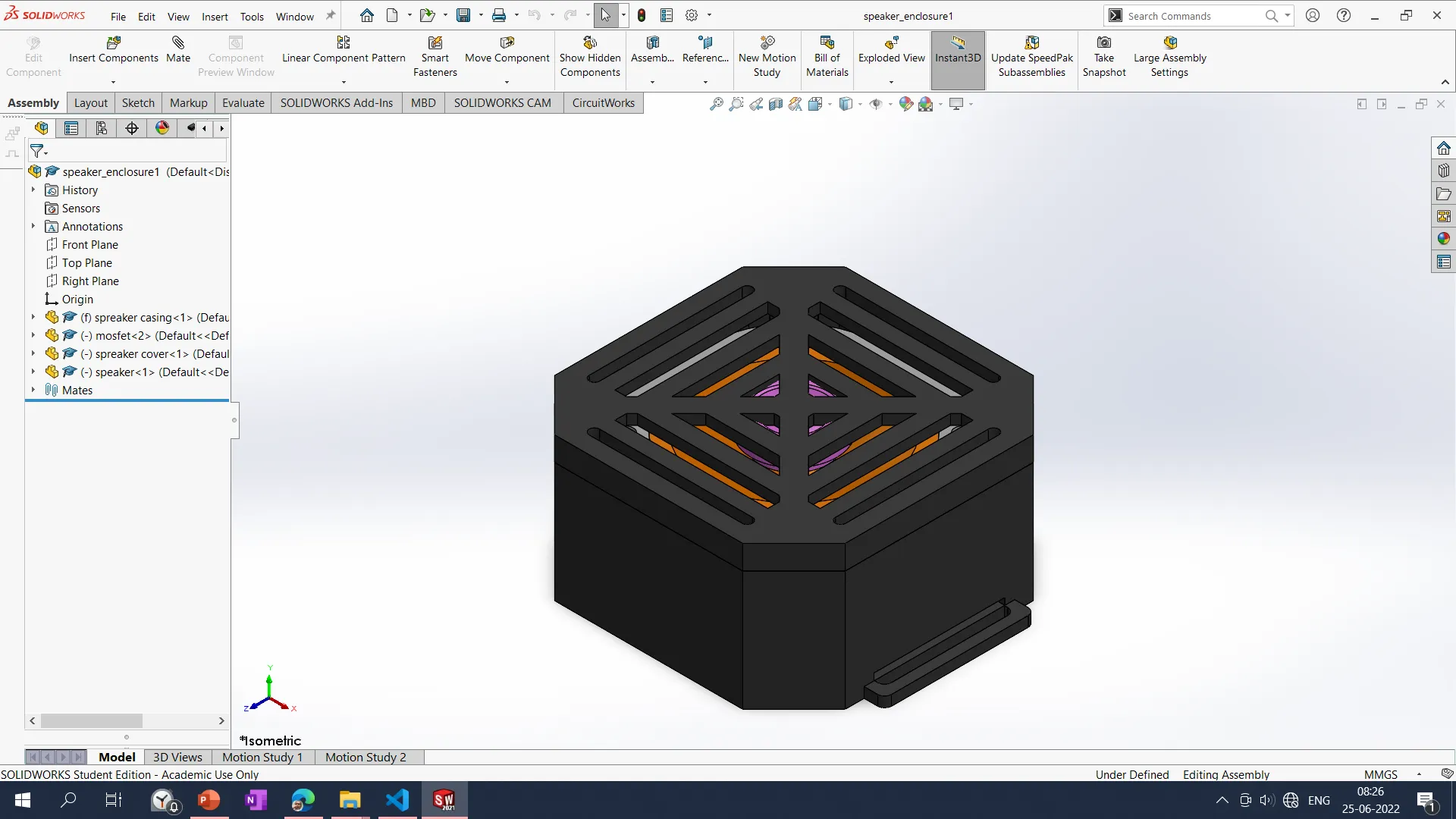
The Speaker casing consists of Speaker and the MP3 breakout board with an sd card.
Electronics Design
Electronics board design was a challenge for me but later by practicing got confidence to design the PCB board. I am struggling to design the board. It took me about ten days to design the board for the final project. Design started with selecting the input and output devices for the wearable device. The device is about human safety, so I want a more robust and reliable microcontroller. Selecting a microcontroller and designing the PCB for project requirements by considering the input-output devices is very challenging. As per the project requirement, I have figured out which type of input and output device I need to use in the project.
I want to design a board that accommodates the following Input/ Output devices:
1. Motion sensor: To sense the wild animals trying to attack from the backside
2. Push Button: Emergency Switch to start Strobe light and Speaker
3. GPS Module: To send live location during the Emergency condition for help. (For Future
Develpoment.)
4. GSM Module: To send a message of GPS location in an emergency. (For Future Development)
Output Devices:
1. BUZZER: Small buzzer only person should be aware of wild animals available at the
backside, will sense using RCWL sensor.
2. LED Strobe Light: To distract the wild animal using a Strobe light.
3. Speaker: To distract wild animals using very Acute noises like Fire crackers/ Gun shoot
noise.
Selection of the microcontroller
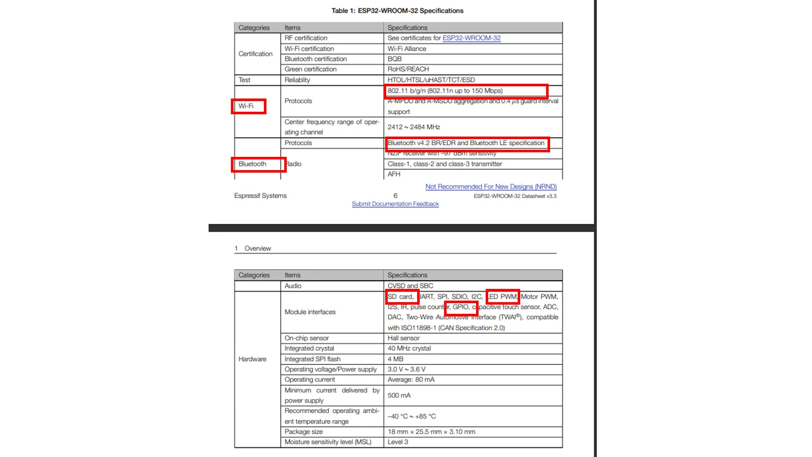
In our lab, we have ESP32 in sufficient quantities. And it is a powerful microcontroller for performing complex tasks. This project is about human safety, so I decided to use the ESP32 microprocessor.ESP32-WROOM-32 is a powerful, generic Wi-Fi + Bluetooth + Bluetooth LE MCU module that targets a wide variety of applications, ranging from low-power sensor networks to the most demanding tasks, such as voice encoding, music streaming and MP3 decoding.
During input devices week only, I designed the microcontroller board by considering all the devices. But I have not considered its size. For the wearable device size of the microcontroller was also a concern. So, by referring to the same connection, I have developed a new one with all the required features. While developing the old PCB board, I considered using the SD card provision to play the music on a Bluetooth speaker. But ESP2 only acts as a sink. It can't send the data over Bluetooth through the speaker. So I removed the connection for the SD card and made provision for the GPS GSM module with an extra two devices required in the future development of the board.Input Devices Week-Microcontroller Design.
Specifications of the ESP32 board is shown below.
The ESP32 is dual core, this means it has 2 processors.
It has Wi-Fi and bluetooth built-in.
It runs 32 bit programs.
The clock frequency can go up to 240MHz and it has a 512 kB RAM.
This particular board has 36 pins
It also has wide variety of peripherals available, like: capacitive touch, ADCs, DACs,
UART, SPI, I2C and much more.
It comes with built-in hall effect sensor and built-in temperature sensor.
The ESP32 peripherals include:
18 Analog-to-Digital Converter (ADC) channels
3 SPI interfaces
3 UART interfaces
2 I2C interfaces
16 PWM output channels
2 Digital-to-Analog Converters (DAC)
2 I2S interfaces
10 Capacitive sensing GPIOs
GPIO 6 to GPIO 11 pins are connected to the integrated SPI flash on the ESP-WROOM-32 chip
and are not recommended for other uses.
GPIOs 34 to 39 are GPIs pins don’t have internal pull-up or pull-down resistors. They can’t be
used as outputs, so use these pins only as inputs.
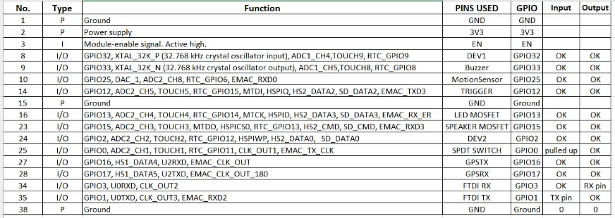
I referred to the pinout of the esp32 to select it for the input-output devices.
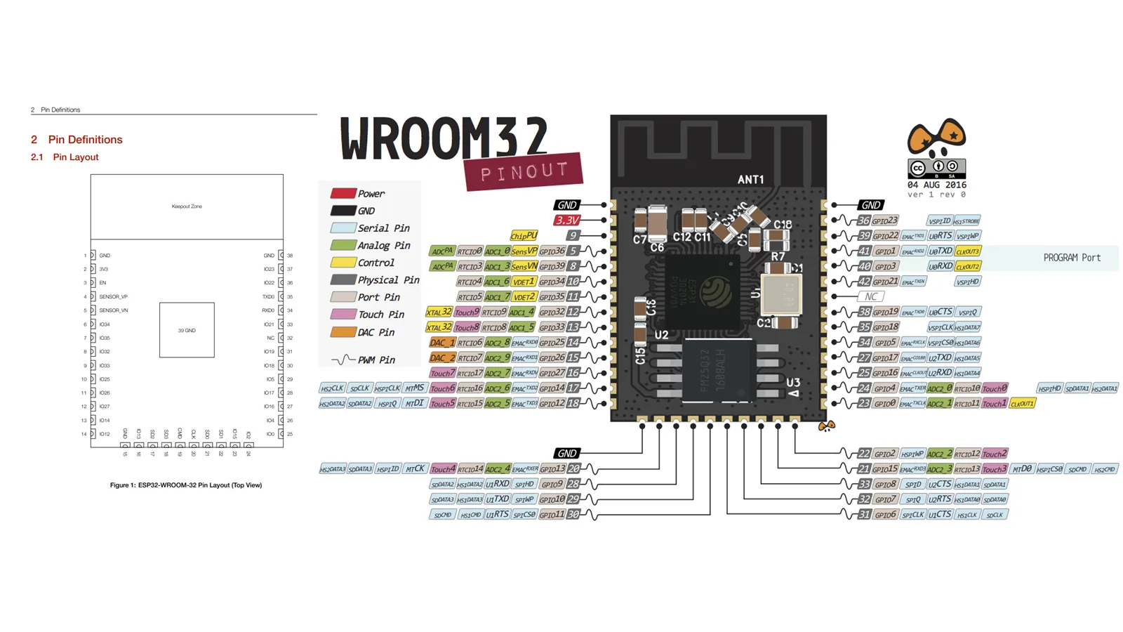
Details of the all the ports in the ESP32 Ic as shown below.
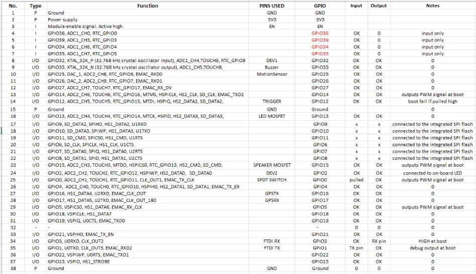
By referring Datasheet I have chosen following ports for the Input output devices.
After deciding the Microcontroller and Input output devices that I need to add, I have decided to do design the board for the Project.
PCB design
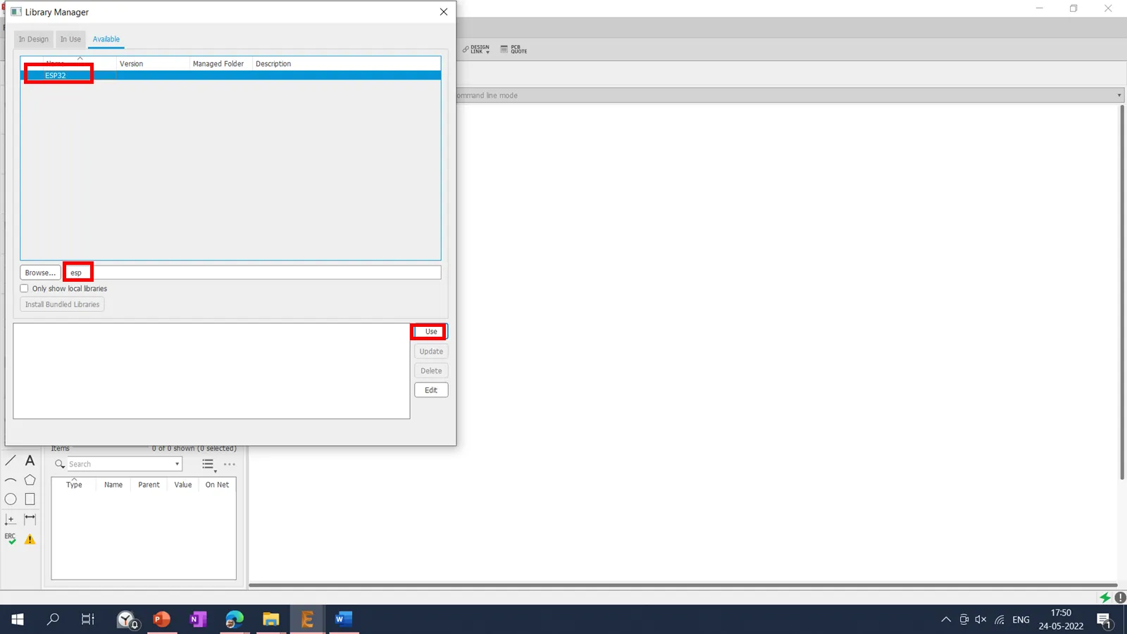
To design the PCB in the Eagle software, I will require an ESP32 library, which is not available
in the Eagle library manager.
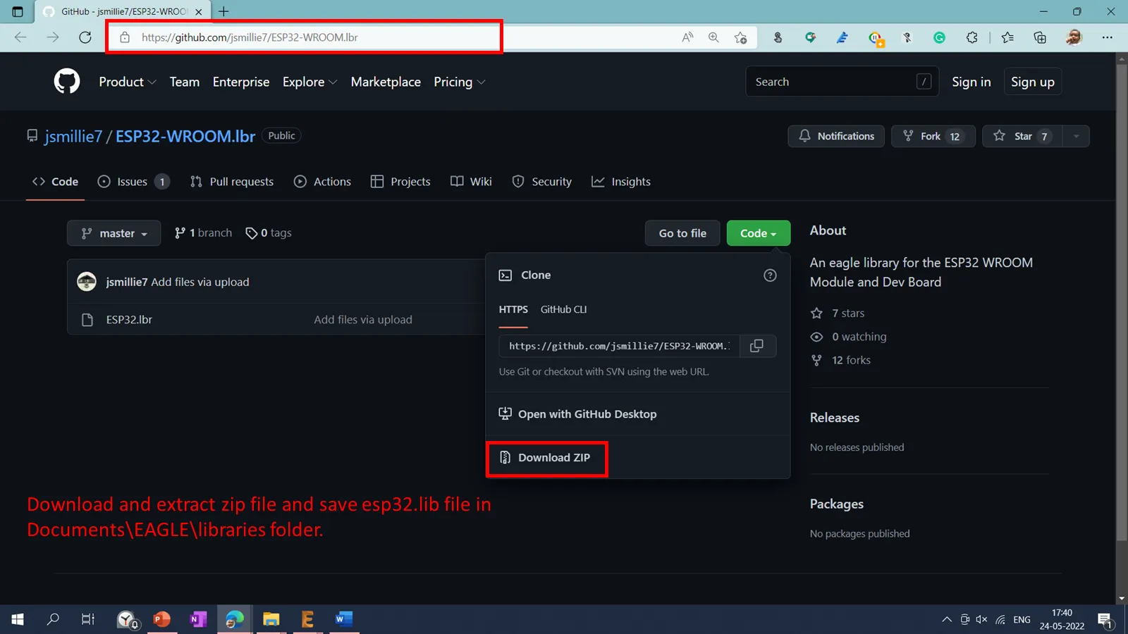
To design the board using the ESP32 microcontroller in Eagle, I have downloaded the esp32
library using the following link ESP32
Library .
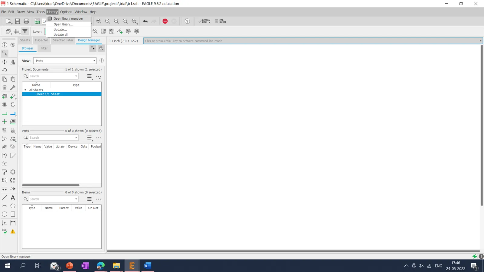
After downloading the library, it is saved in a documents-Eagle-Library folder.
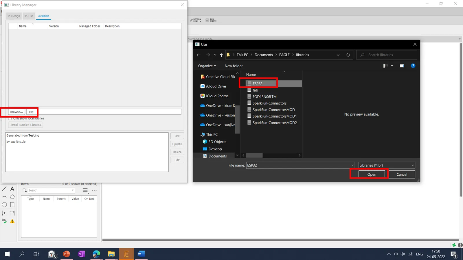
Then I have added library into the project using Library Manager.
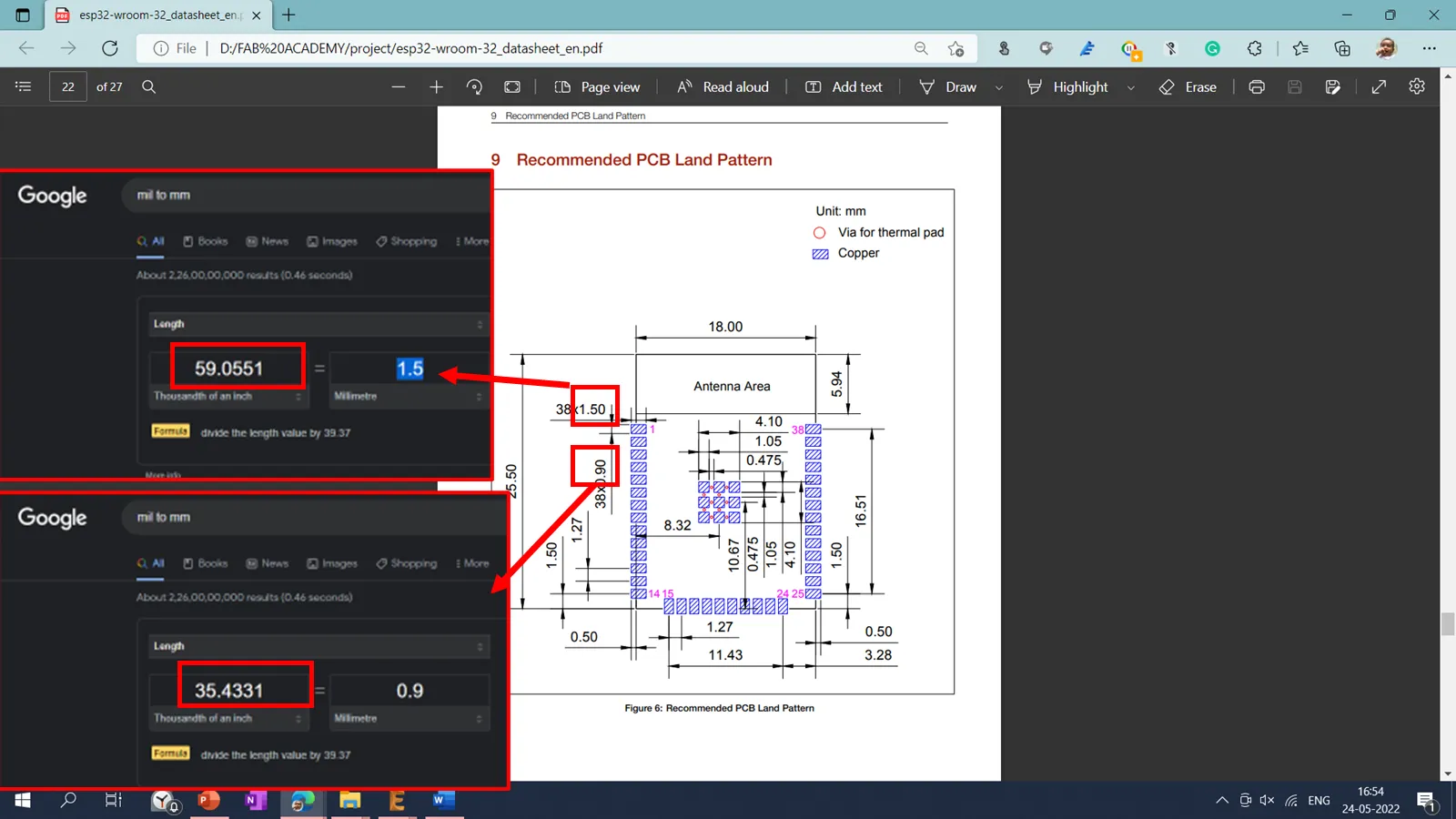
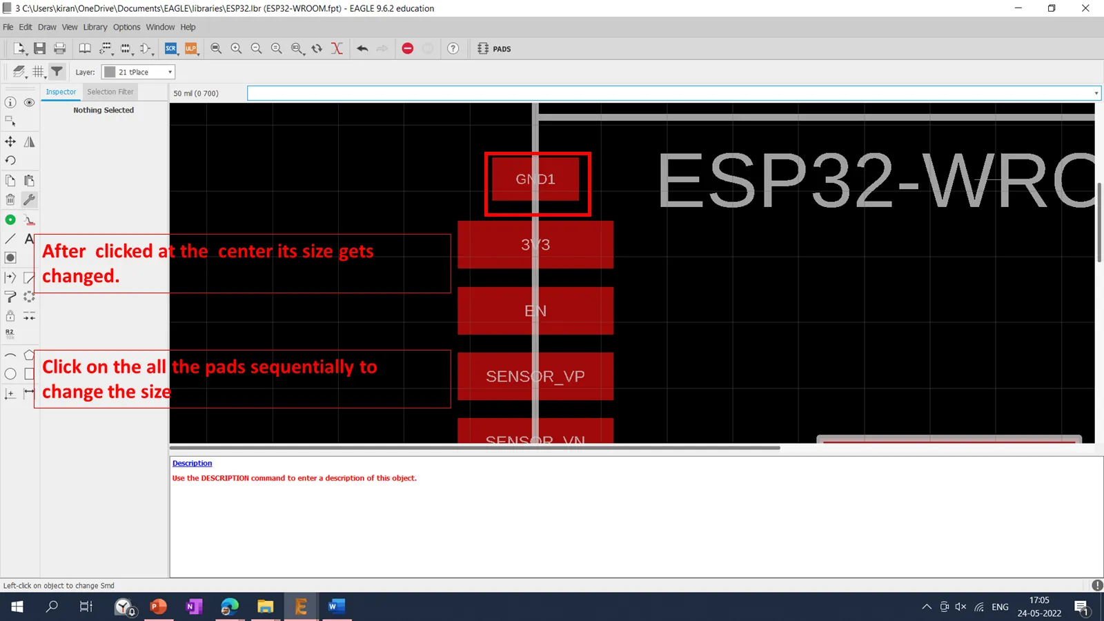
After reading the datasheet of ESP32, the standard pad size for the microcontroller pads was mentioned. Then I changed the pad size of ESP32 using the following procedure.
Following process was followed to change the pad size. I we cant change the pad size, we cant do machine the pad using milling machine. Hence it is important to change the pad size. .
Go to the Library manager
You can observed change in the size of the pads before and after the modification.
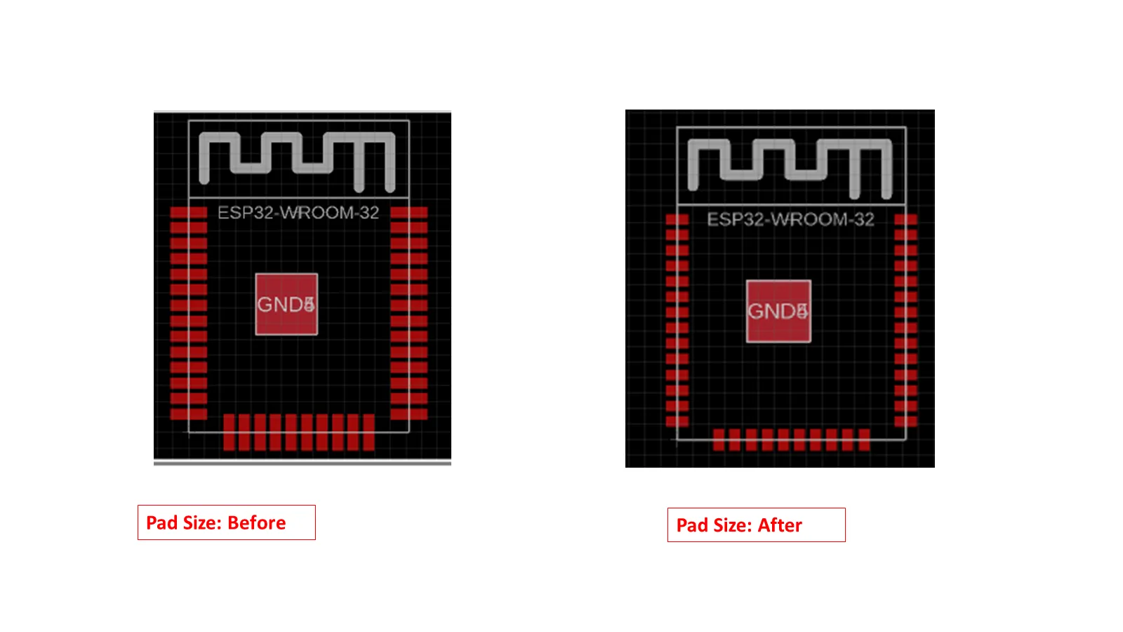
Then save as this library with the new name say esp32_1. An we need to save the file in the same folder.
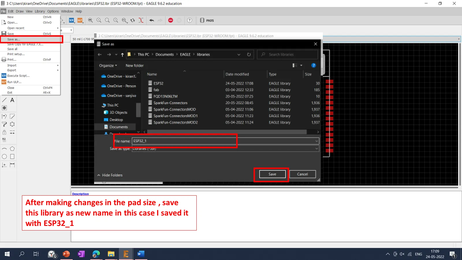
Then we need to add the modified library into the library manager.
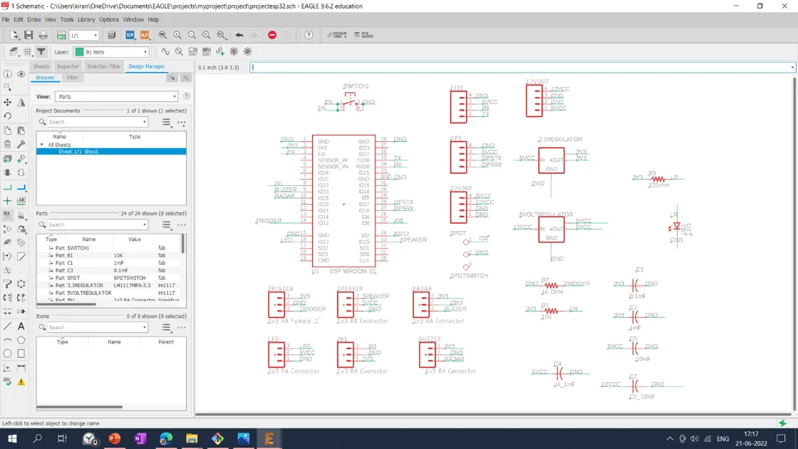
After finalization of the EPS32 library I started to add the different components in the Schematics. I have referred the initial schematic given by Prof. Neil.in the Embedded programming ESP32 Board. For different connectors used in the board, I have downloaded SparkFun connectors libraries using the SparkFun-Connectors Library. Also added the Transistor library downloaded using the link transistors-lm1117 library.
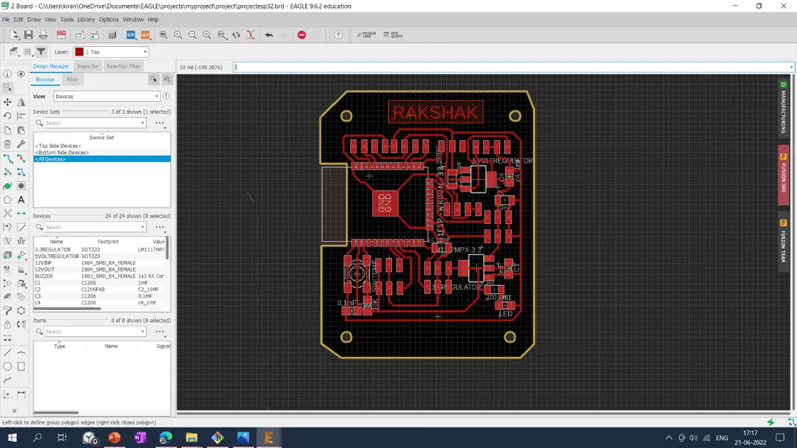
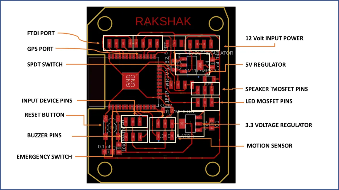
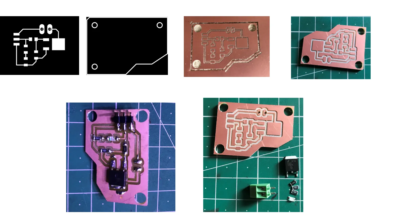
Final Board design of the projet is shown below.
After finalizing the board,traces were selected using top layer and exported into a .png monochrome file with 1000 dpi resolution. In the same way, the interior is selected using the dimension layer and exported into a .png monochrome file with 1000 dpi.
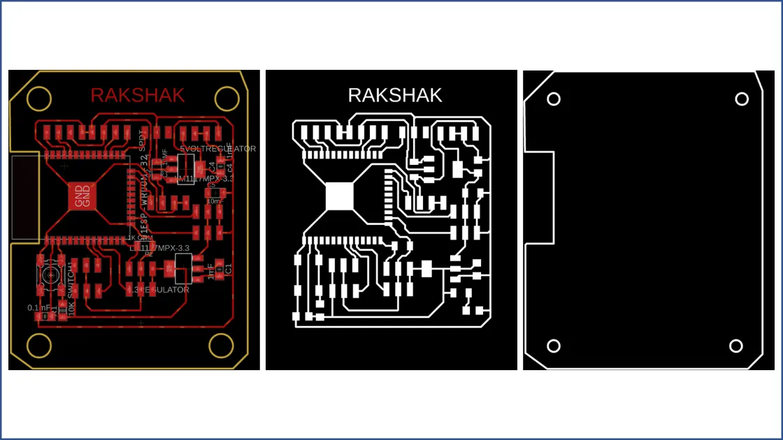
Placement of different components on the board is shown below.
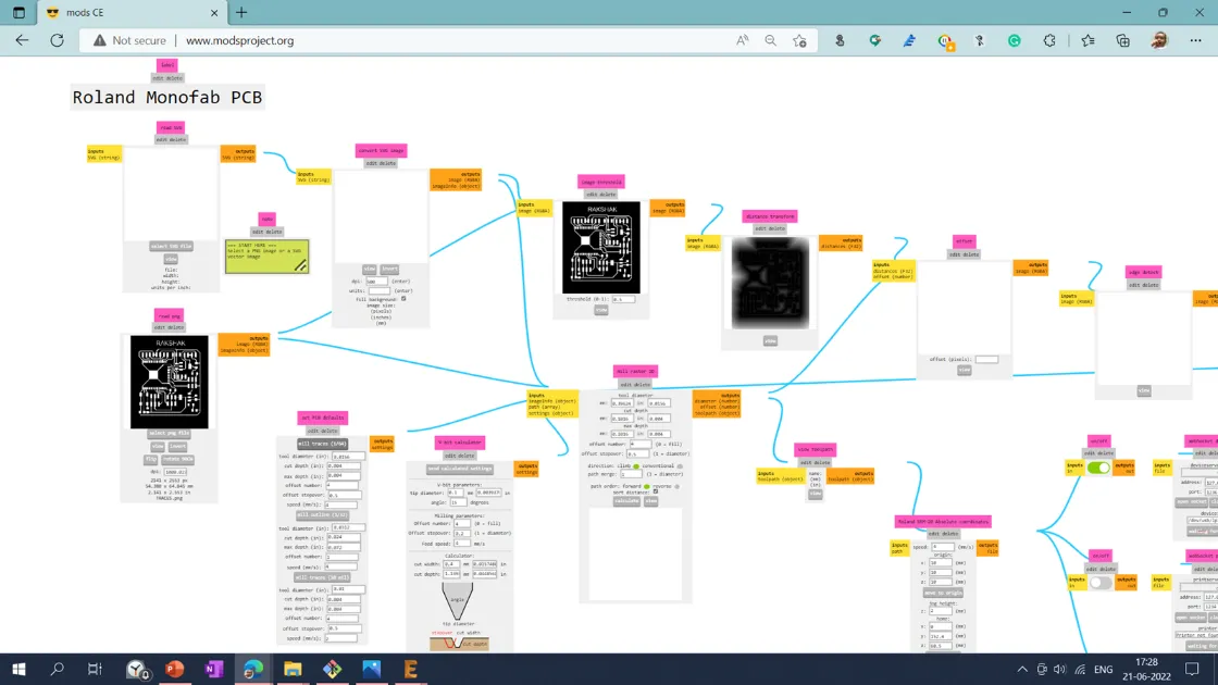
Tool Path Generation
I have used modproject http://www.modsproject.org/ tool for the tool path generation. I have imported traces and the interior .png file into the mods project and selected the 1/64 tool for the traces and 1/32 for the interior.
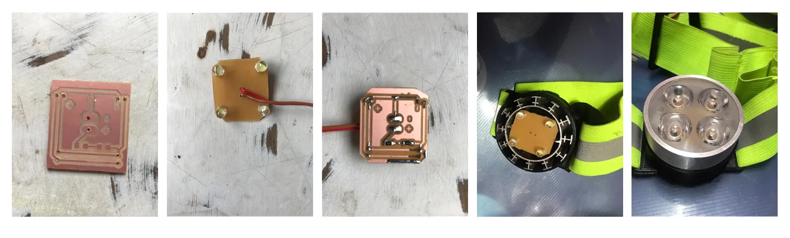
Machining and soldering
After downloading, the .rml file from the modsproject file is imported into the SRM20 PCB milling machine. PCB plate fixed in the bed and V shape tool is mounted in the collet and set tool home position using drop test. Then I imported the .rlm file into the Vpanel for SRM20. And start the cutting operation.
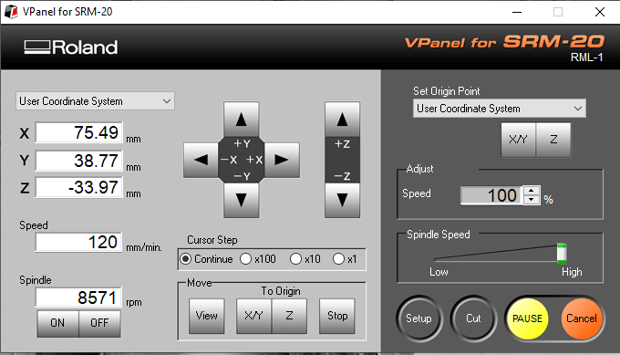
PCB milling using SRM20 is shown below.
List of the components used.
1. Resistor: 10K- 1 Qty
2. Capacitor: 1uF- 2 Qty
3. Capacitor: 10uF- 2 Qty
4. Capacitor: 0.1uF- 1 Qty
5. Push button (No)- 1 Qty
6. Sliding switch- 1 Qty
7. 3.3v voltage regulator (SMD)- 1 Qty
8. Microprocessor ESP32 Wroom- 1 Qty
9. FTDI Pin (4pin)- 2 QTY
10. 3x1 make header pins- 4 QTY
11.5V Voltage Regulator: 1 Qty
12. Resistor: 10K- 1 Qty
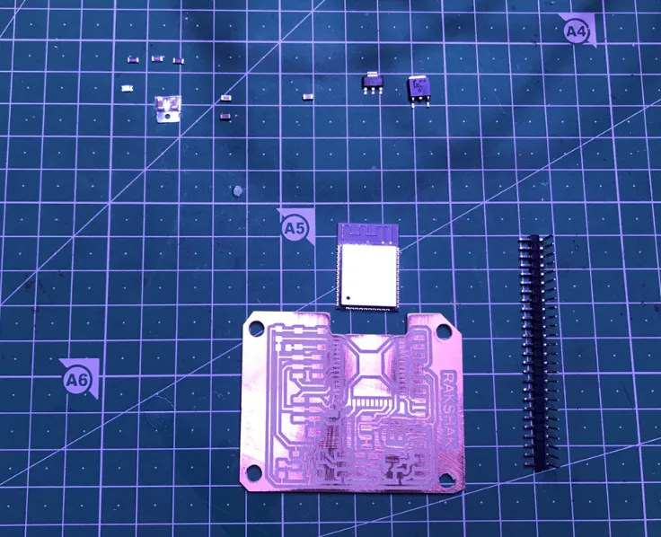
The process of the PCB board, from designing to the soldering, is shown below.
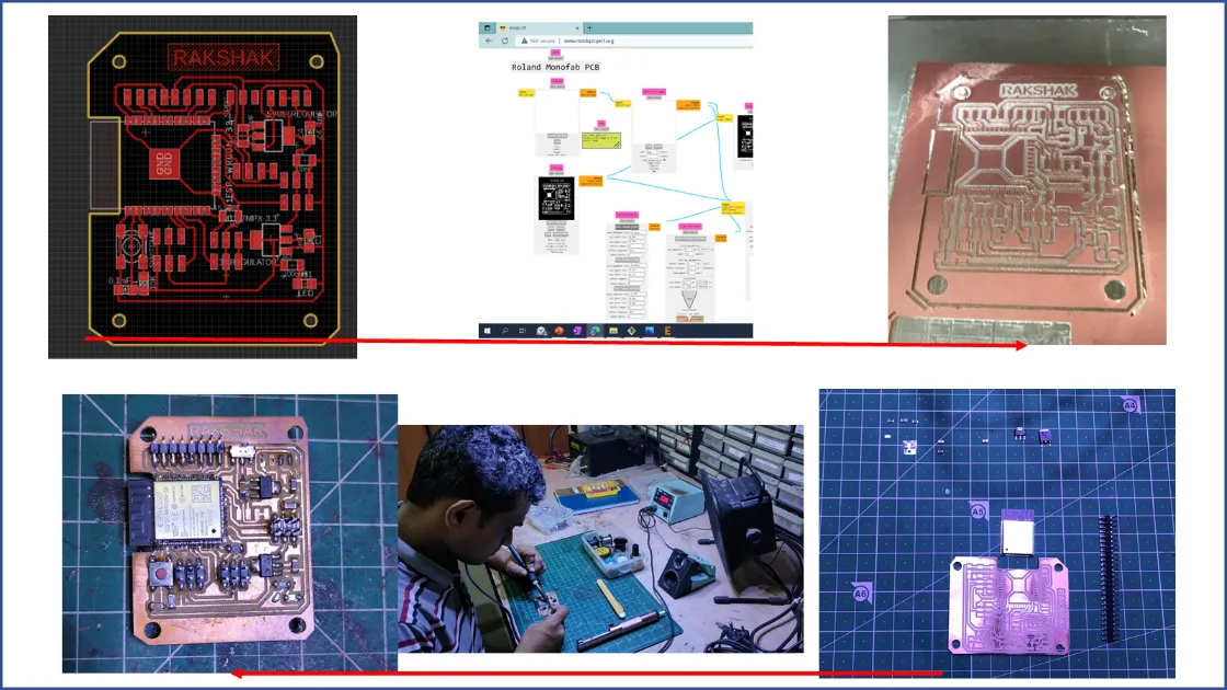
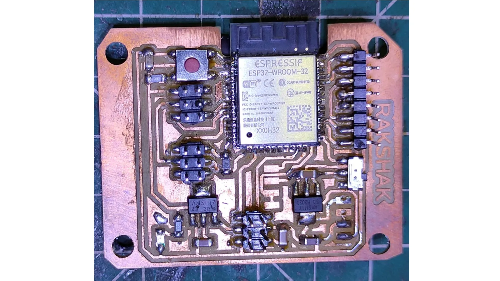
The main microcontroller board with the stuffed electronics components with soldering is shown below.
MOSFET BOARD DESIGN
For switching On and off the LED lights and Speaker, I have used
MOSFET. I have used N-channel Enhancement mode FQP50N06L MOSFET. N channel MOSFETs are used for
the high current application.
To turn on an N-Channel Enhancement-type MOSFET, apply a sufficiently positive voltage (VDD) to
the drain of the transistor and a sufficiently positive voltage to the Gate of the transistor.
This will allow a current to flow through the drain-source channel.
So, with a sufficiently positive voltage, VDD, and positive voltage applied to the Gate, the
N-Channel Enhancement-type MOSFET is fully functional and in the 'ON' operation.
I have designed two different MOSFET boards for switching on and off for speakers and LED
strobing lights.
The signal pin is connected to the Gate of the MOSFET. The ground is connected to the source.
The ground of the primary power supply is supposed to be provided to the LED connected to the
drain.
The Gate is connected to the signal pin of the microcontroller. As the signal pin on the voltage
across the source and Gate is 3.7 v will be activated, starting the current flowing from drain
to source. For the LED, all the positive connections of the front and back LEDs are connected to
the source. And the ground is connected to the drain of the MOSFET. When the signal pin is low,
the voltage between the Gate and the source is 0V, so no current flows from the drain to the
source. So no current will flow from VCC to the ground through the LEDs. As the signal pin is
HIGH, the current will start flowing from the drain to the source, and then the current will
start flowing from VCC to the ground through the drain, and the LED will be switched on.
Specifications of MOSFET are as shown below.

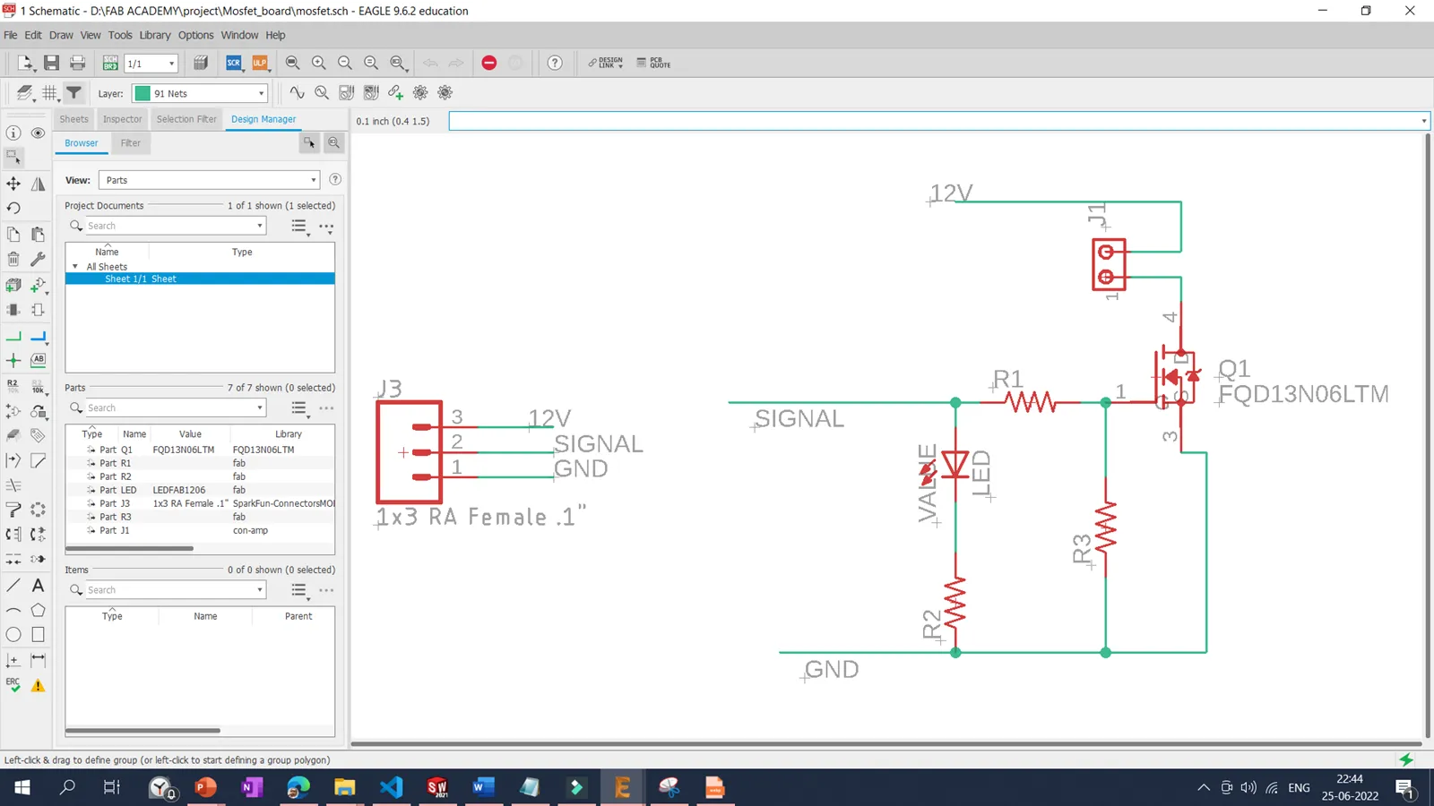
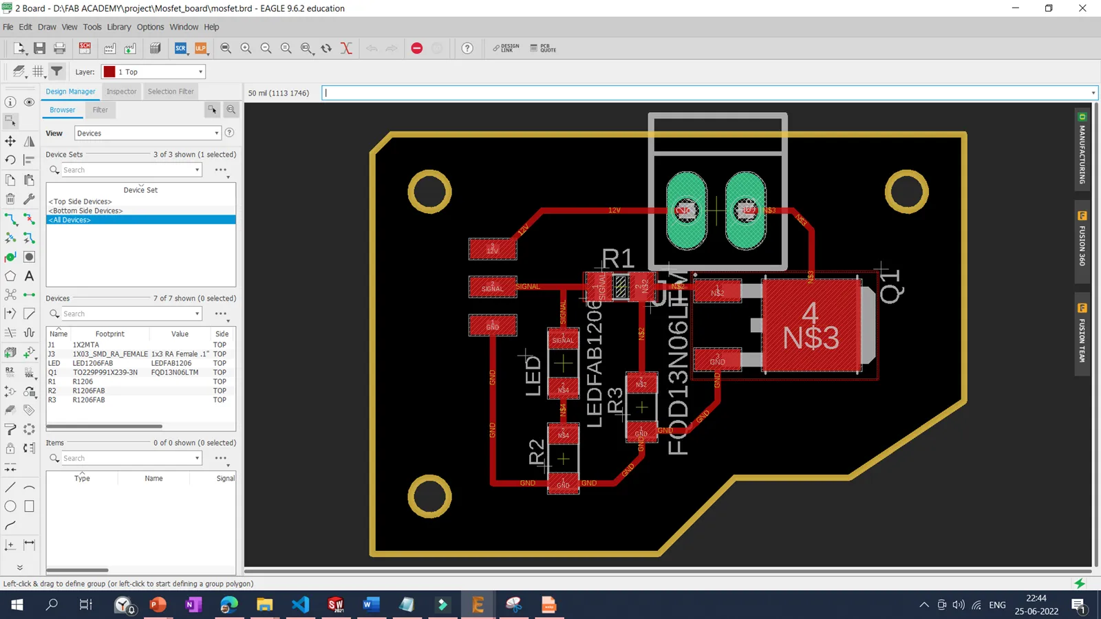
I have designed the MOSFET board for the LED strobe and speaker. The Mosfet board schematics and board are shown below.
After downloading the traces and interior with 1000 dpi in.png format, the toolpath for the SRM20 PCB milling machine is generated in the modsproject online tool. And then, the toolpath is imported into the SRM20 for the PCB milling.
List of the components used.
1. MOSFET : FQP50N06L- 1 Qty
2. LED: RED- 1 Qty
3. RESISTOR : 1K- 2 Qty
4. RESISTOR : 220 OHM- 1 Qty
5. 3x1 make header pins- 1 QTY
3D printing
For the wearable device, I want to make customized parts that can be
easily matched with the belt. Initially, I started with the microcontroller board casing. I have
designed the microcontroller board casing to accommodate a microcontroller board with 2 MOSFETs, a
power switch, an emergency switch, Power plug for the battery.
Also, the speaker casing should accommodate a 4-watt speaker with an MP3 breakout board.
Head lamp casing designed to support the heat sink of LEDs.
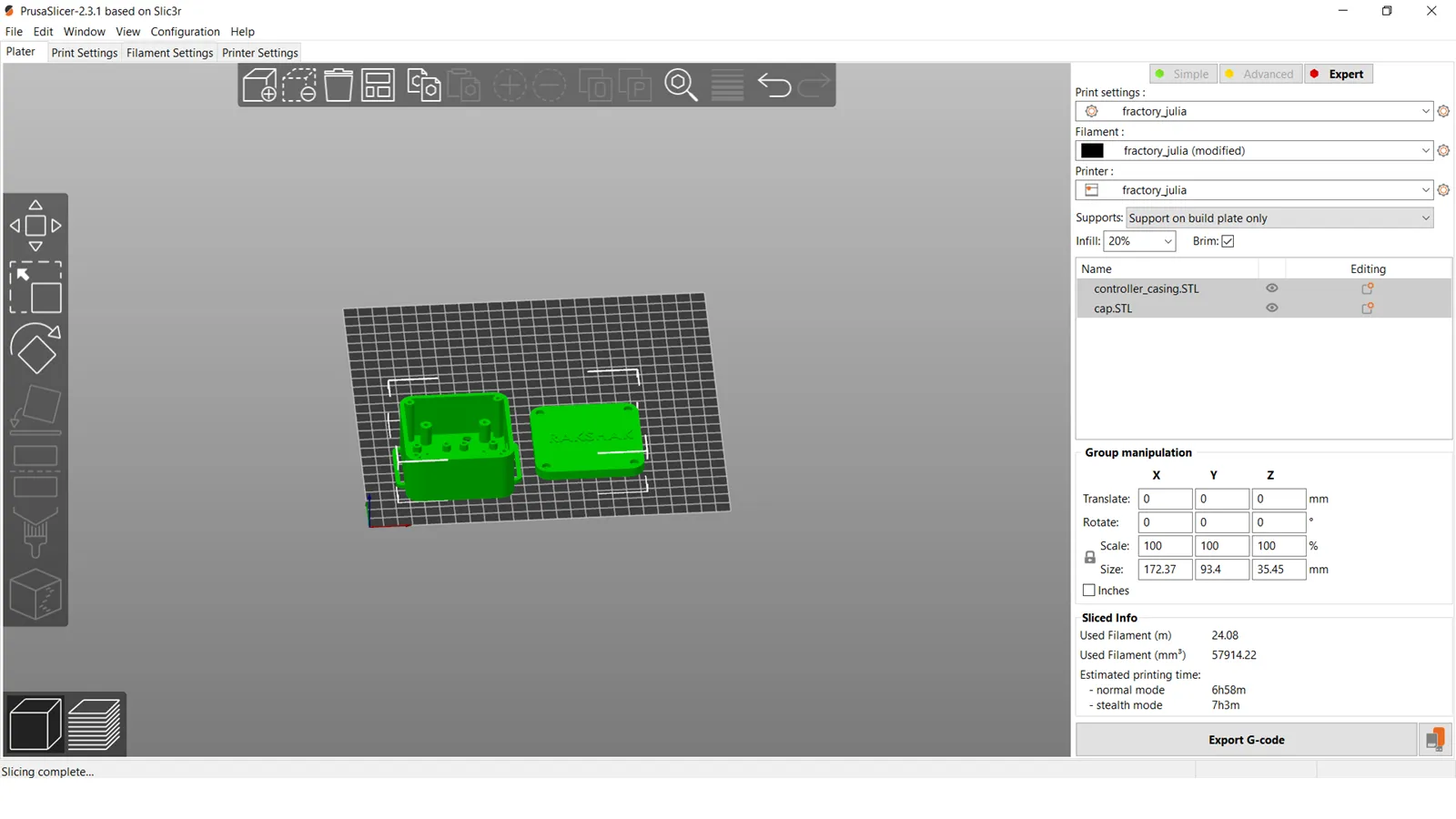
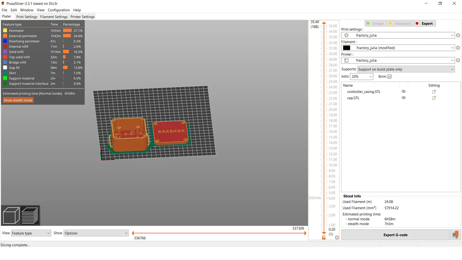
After designing the part and converting it into the .stl file format, I have used a Prusa slicer to
slice the part and convert the .gcode for the 3D Printing. Slicing is a dome with 0.2 mm layer
height, 40% infill, with support generation with Brim Layer for better bed adhesion. Black colored
PLA material was used with 210 nozzle temperature, and 60-degree bed temperature settings was used.
Slicing of the 3D printing is shown below.
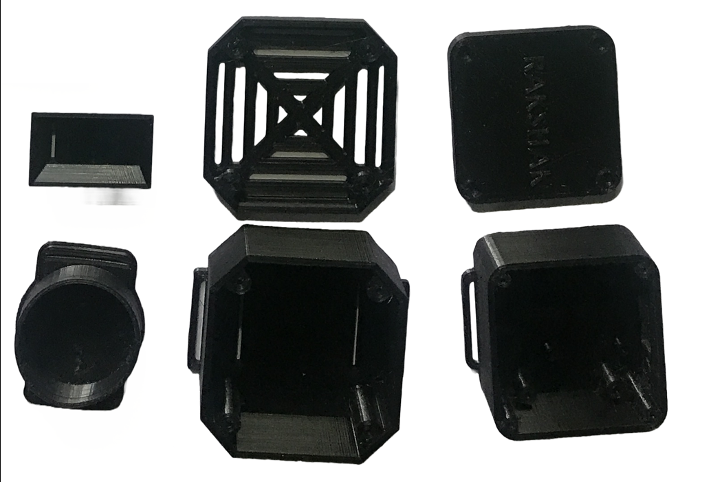
Fraktory Make Julia Extended 3D printer was used for 3D Printing of all the casings used in
the device.
3D printed parts designed, printed and used for the device are as shown below.
Laser Cutting Machine
To woven the LEDs in the Safety belt, I have cut Led-shaped circular holes using a laser cutting machine. I have measured the distance between two dome-shaped LEDs, measured the diameter of Leds, designed the sketch in Solidworks, and converted it into the .dxf extension. Then .dxf file is imported into the laser cad software. Then .gcode file is exported to the Laser cutting machine. In our lab we are having SIL Make 60 wat laser cutting machine. Process parameter 10% power and 150mm/min speed was used to cut the holes in the fabric. One clip was cut using a laser cutting machine for the headlight belt adjustment.
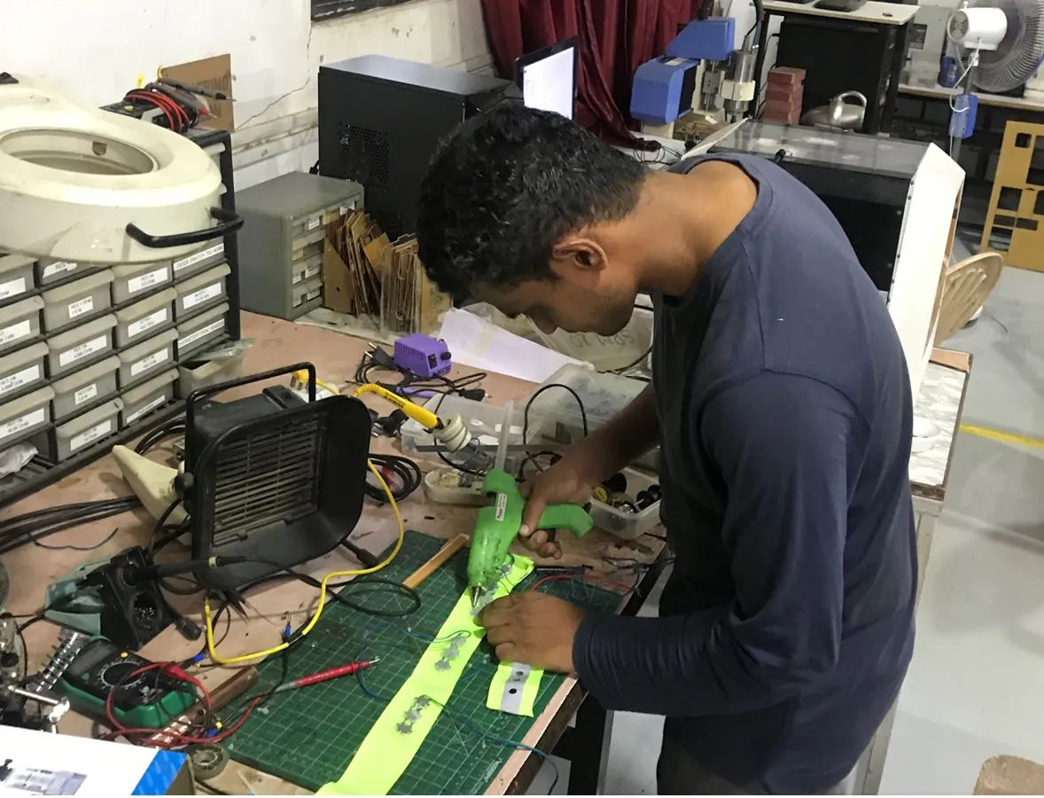
Belt Stitching
A Brother Make A150 Computerized sewing machine is used for the stitching. I do some simple stitching, and the remaining part is done by Ms. Priyanka, Fabriacademy Instructor at Vigyan Ashram. I open the stitches of the safety belt to add the 3d printing microcontroller and speaker casing. I also stitched one small pocket for the battery placing. I have stitched the new belt and attached it to the main wearable device for the headlight placing. Serially connected Dome-shaped LEDs are glued with laser-cut belt fabric and stitched to the central belt at the front and backside. The front side, left, and right belt consists of 3 LEDs each, and the back side belt connected to the headlamp consists of 5 LEDs. For wire routing, I have stitched the fabric sleeves of another black cotton fabric to the primary device at the back of each belt to hide any wire connection.
Electronics Peripherals
Input Device
For this project, I want to detect the motion of wild animals following a person and trying to attack him. Several proximity sensors detect the movement of living or non-living objects via ultrasonic, infrared, etc. They have a limited range of detection. PIR and RCWL radar sensors are good choices for living object detection. The radar sensor is a low-cost, effective sensor that works on the doppler effect. But the negative side of Radar is that it detects any moving object living and non living. I have attached it to the wearable device, but it detects the other object and gives a signal when a person moves with the sensor. For this reason, I have canceled using the radar sensor and moving with the PIR sensor. The beauty of the PIR sensor is that it detects living objects only within a range of 7 meters.
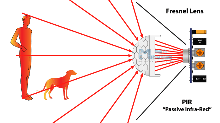
A passive infrared sensor (PIR sensor) is an electronic sensor that detects infrared (IR) light
emitted by nearby objects. Most commonly, they are utilized in PIR-based motion detectors. It is
an inexpensive sensor capable of detecting the presence of humans or animals. PIR sensors are
frequently employed in security alarms and automatic lighting systems.
PIR sensors detect general movement but do not reveal who or what has moved. Towards this
end, an IR imaging sensor is necessary.
PIR sensors are usually referred to as "PIR" or "PID," which stands for "passive infrared
detector." Passive refers to the fact that PIR devices do not emit energy for detection. They
detect only infrared radiation (radiant heat) emitted or reflected by objects.
Any living body with a temperature above absolute temperature emits invisible radiation to
the normal eye. It senses these passive infrared rays to detect live wild animals.
As the diagram indicates, this HC-SR501 PIR sensor module has three output pins: Vcc,
Output, and Ground. Since the output pin is 3.3V TTL logic, it is compatible with various
platforms, such as Arduino, Raspberry, PIC, ARM, 8051, etc.
PIR sensor can detect animal or human movement within a required range. A PIR is made of a
pyroelectric sensor that detects different levels of infrared radiation. The detector itself
does not emit any energy but passively receives it.
PIR Sensor Working.
The PIR Motion Sensor Detector Module HC SR501 allows you to sense motion. It is almost always used to detect the motion of a human body within the sensor's range. The module has an onboard pyroelectric sensor, conditioning circuitry, and a dome-shaped Fresnel lens. It has a delay time adjustment Potentiometer and sensitivity adjustment potentiometer.
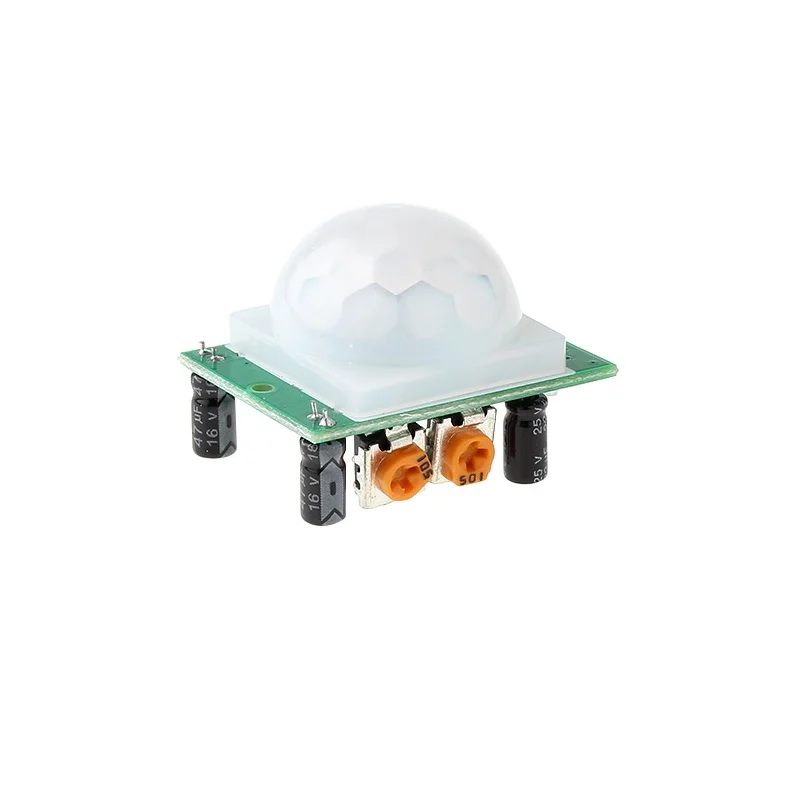

Sensor Specifications:
Model :PIR HC-SR501
Operating Voltage (VDC) :4.5 ~ 20
Average Current Consumption (mA) :0.06
Distance Measuring Range (CM) :300 ~ 700
Output Type :(High/ Low-level Signal) 3.3V TTL output
Dimensions (mm) LxWxH :32 x 24 x 18
Weight (gm) :10
Working Temperature Range (°C) :-20 to 80
Detection Angle :<140°
Delay Time :5 to 200s (Can be Adjusted, Default 5s +/- 3%)
Features
◦ Automatic induction: to enter the sensing range of the output is high, the person leaves the
sensing range of the automatic delay off high, output low.
◦ Photosensitive control (optional, not factory-set) can be set to photosensitive control,
day or light intensity without induction.
◦ Temperature compensation (optional, factory reset): In the summer, when the ambient
temperature rises to 30 °C to 32 °C, the detection distance is slightly shorter. Temperature
compensation can be used for performance compensation.
◦ Triggered in two ways: (jumper selectable)
◦ non-repeatable trigger: the sensor output is high, the delay time is over, and the output
is automatically changed from high level to low level;
The sensor output is high, and the delay period. If human activity is in its sensing range, the
output will always remain high until the people leave. The output will be low after the delay
(the sensor module detects a time delay period and the starting point for the delay time to the
last event).
◦ With induction blocking time (the default setting: 2.5 s blocked time): sensor module
outputs after each sensor output (high into low), followed by a blockade set period. During this
period, the sensor does not accept any sensor signal. This feature can be achieved through
sensor output time "and" blocking time "interval between the work can be applied to interval
detection products; This function can inhibit a variety of interference in the process of load
switching.
◦ Wide operating voltage range: default voltage DC4.5V-20V.
◦ Micropower consumption: static current <50 microamps, particularly suitable for
battery-powered automatic control products. ◦ Output high signal: easy to achieve docking
with various circuits.
I have tested the PIR sensor with the old microcontroller board by connecting the sensor pin GPIO pin of board 19. As the motion detected led attach with GPIO pin 33 will be on. The program for the PIR sensor is shown below.
The following video shows the working of the PIR sensor.
Then I have the final testing on the device for motion detection.
Output Device
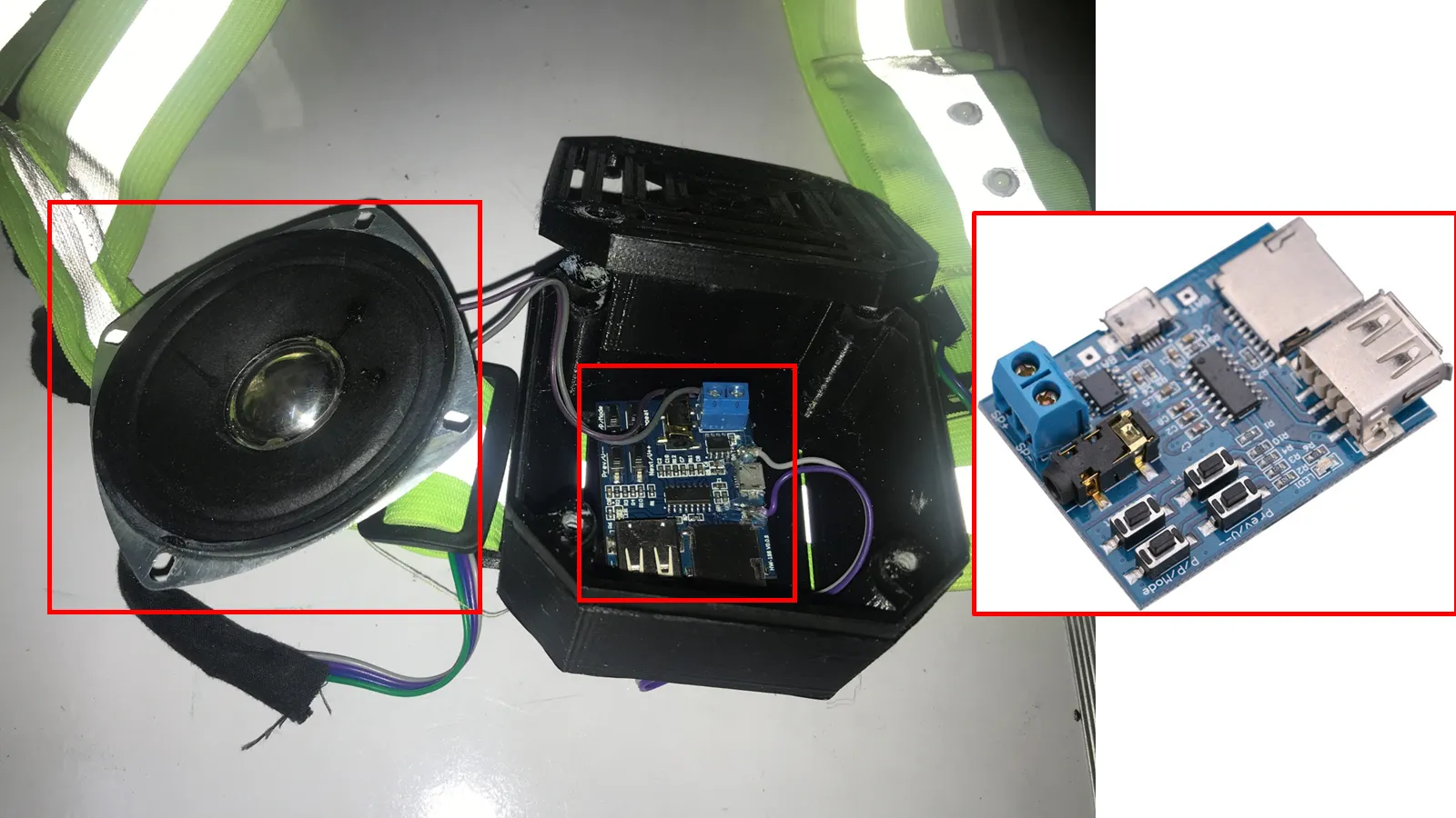
MP3 Decoding Board
I wanted to produce a loud firecracker sound to distract the wild
animal. I have used the Non-Destructive MP3 Decoding Board to connect 4 Ω 3W speakers to produce
a loud sound.
The Non-Destructive MP3 Decoding Board with Self-Powered TF Card, U Disk Decoded Player module,
is used for playing tracks in the MP3 format stored on a micro SD card or USB memory. The
perfect device for playing messages on platforms, warning signals, etc. Superior sound quality.
The onboard 2W mono amplifier (5V power of up to 3W) is connected to the speaker
(recommendation: 4 Ω 3W speakers), 3.5mm gold-plated headphone jack can connect with headphones
or external audio with a MicroUSB port. The mobile power supply, 3.7V lithium battery, or USB 5V
power supply. It supports TF Card (mobile phone memory card) and U Disk Play Mode.
On the SD card, I have saved the Firecracker Music MP3 file. Then SD card is connected to
the MP3 decoding board.
The decoding board is set on play-to-mode using buttons provided on the board. The MOSFET board
gives power to the decoding board with controlled actuation from the microcontroller. The MOSFET
will act as a switch controlled by the microcontroller when the emergency button switches.
To produce loud sound 4 Ω 3W speaker was used and connected to the MP3 board shown in image.
A push-button is added to the microcontroller board casing; when pressed, the speaker will
start, and the LED light will start strobing.
Emergency Switch
The Black R13-507 16mm No Lock Push Button Momentary Switch 3A 250V is used for the emergency switch. It is an SPST switch, and the No-Lock Self-Reset OFF/ON push-button switch is fitted into the microcontroller board mounting with an 8mm diameter hole.
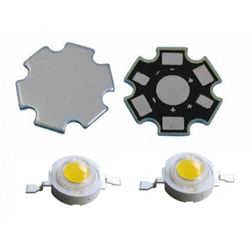
My project is based on the attachment of the light. I want the intense light that can show wild animals from a long distance and distract them with the strobing effect. I used 14 × 20mA 28500mcd 5mm Round Through Hole White LED for the headlight. I Designed the PCB for the through-hole LED and Placed it in the Heat sink with a reflector.
To add more light effect, I woven led strip into the jacket. 3Watt dome
shape LEDs heat sink are used in the belt's front and back strap.
Specifications:
• Wattage: 3W
• Operating Voltage: 3.2-3.5V
• Current: 300mA
• Luminous Intensity: 110-120LM
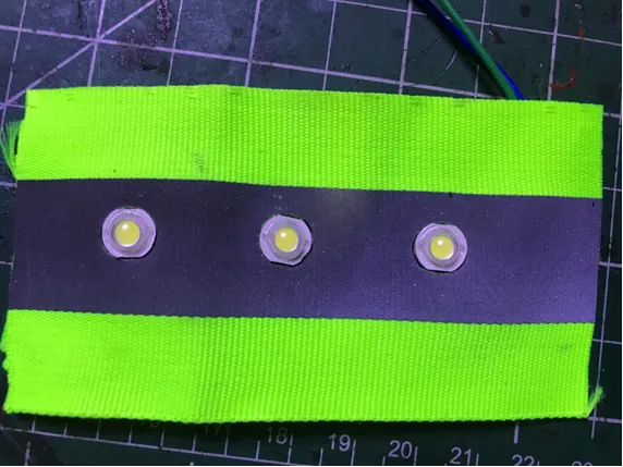
Set of 3 and 5 LEDs are connected in parallel and glued to the belt strap consisting of holes
cut with laser cutting.
.webp)
LI-PO Battery
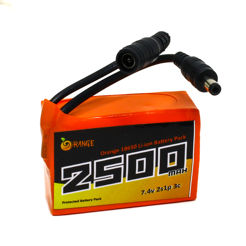
I used a 7.4 volt 2500mAh battery for this project. Earlier, I purchased this battery for a prosthetic hand project. I decided to use the same battery for the project. For this spiral, the battery can support the total device load and work for a long time (about 4 hours). The LIPO battery has more weight compared with the LI-ION battery. I inquired about the battery, but I proceeded with the LIPO battery due to unavailability. In the next spiral, I will use a Lithium-Ion battery. It is small in size and weight compared to Ni-Cd, Ni-MH, and lead-acid batteries. With the inbuilt charge protection circuit, the battery pack can be directly charged with the DC power adapter, so there is no need to use the specialized battery chargers and worry about overcharging.
System Integration
Integrating all the devices on the safety belt was a very challenging
task for me.
For the wearable device, the electric connection is a crucial task. All the connections should
be very systematic and work properly. From an aesthetic point of view, all the connections
should be hidden at the back of the belt without appearing on the belt.
I have stitched the fabric sleeve inside the belt to route all the electric connections through
it. So I can manage all the connections systematically.
All the components used in the device are as shown below.
Head Lamp:
The Headlamp LED board with heat sink is placed inside the 3D printed bracket and mounted on the arrangement made in the safety jacket for the headlight. Its electric connections are routed through the fabric sleeve stitched inside the belt to hide the connections.
LED Lights
For strobing effects, two 3- LED light strips are stitched on the front side belt of the device, and five led lights are set on the back sides of the belt in the neck region. The connection of these LED lights is routed through the fabric sleeve stitched precisely at the back of the belt to hide electric connections. All three LED sets are connected with parallel circuit connections.
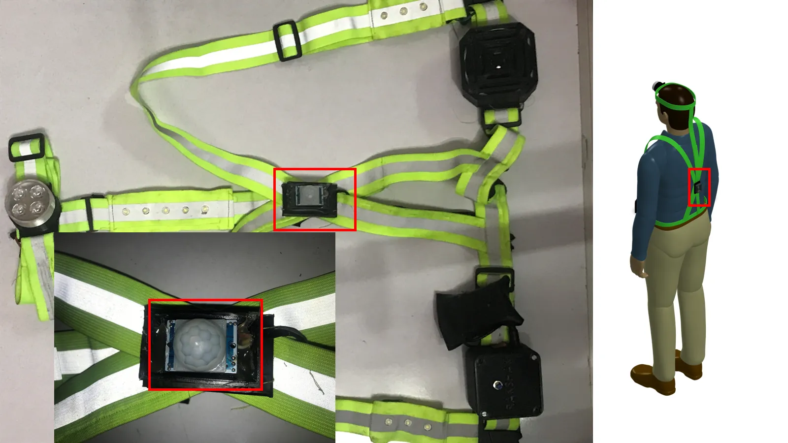
PIR Sensor
The PIR motion sensor is located just below the 5 LED sets on the back of the belt. A PIR sensor is attached to the specially designed 3D printed part and stitched to the belt. The VCC and ground connections are connected to the headlamp connections to supply 5V power to the sensor. The sensor signal wire is connected to the microcontroller board with its power pins through the fabric sleeve.
Microcontroller Casing
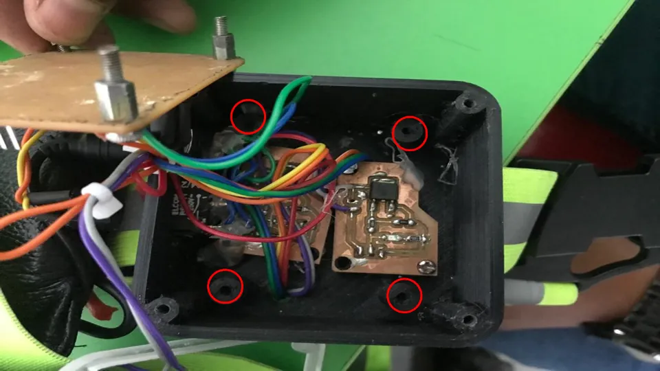
Microcontroller casing design to place 2MOSFETS, microcontroller and buzzer inside the case ,
SPDT switch, emergency switch, and power plug on the wall of the casing.
Screws secure the MOSFETs to the bottom of the case, and 3mm bolts hold the microcontroller
board above them with guided pins.
The microcontroller board casing is placed on the vest zone's left side.
The MOSFETs are connected to the microcontroller via pins for signal, VCC, and ground.
The SPDT switch mounted on the board is directly connected to the headlamp. Power will be
applied to the headlamp as soon as the device is turned on.
A small buzzer is connected to the microcontroller board placed inside its casing.
An emergency switch (an SPST switch) is mounted on the cap of the microcontroller casing.
Speaker Casing
The speaker casing is placed on the right side of the device in the vest zone. It consists of a speaker and an MP3 decoding board. The MP3 board connections are connected to a MOSFET mounted inside the microcontroller case. Its connections are routed through the fabric sleeve attached to the belt in the vest region.
Battery
For the battery mounting, one small pocket is stitched to the belt on the right side of the microcontroller board. The battery is connected to the power plug mounted on the microcontroller board casing.
All the device connections are routed through the fabric sleeve, which minimises the complexity of wiring and the product looks elegant without messy wiring connections.
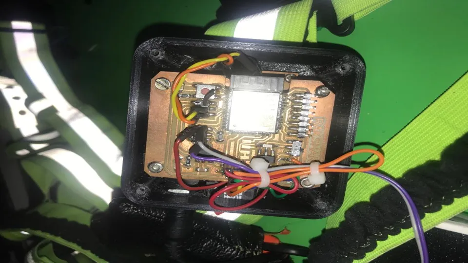
The electrical connections of the controller board and speaker are as shown below.
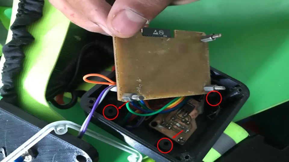
While designing the casing, I made the provision to place the microcontroller board on the top of the MOSFET board with printed studs.
But due to wiring connections and the power plug placement, there are problems with fixing the board.
As per the global evaluator's suggestion on placing the microcontroller board in the casing, I have placed 3mm hexagonal pillars between the Mosfet board and the main microcontroller board.
A microcontroller board with hexagonal pillars is fixed with a 3mm bolt onto the casing. This arrangement will help avoid touching boards with other electronic peripherals.
Still, header pins attached to the microcontroller board create a hurdle to fitting the cap of the board onto the casing. To avoid this, I have cut white and transparent acrylic sheets to add the space between the top of the board and the casing cap. These plates are cut so that mounting holes will match with holes cut on the plate. Then board casing assembly was done, placing laser-cut plates between the cap and container of the casing.
Still, header pins attached to the microcontroller board create a hurdle to fitting the cap of the board onto the casing. To avoid this, I have cut white and transparent acrylic sheets to add the space between the top of the board and the casing cap. These plates are cut so that mounting holes will match with holes cut on the plate. Then board casing assembly was done, placing laser-cut plates between the cap and container of the casing.
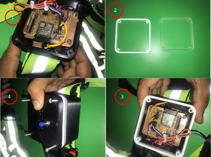
The following video shows the updated case with the working device.
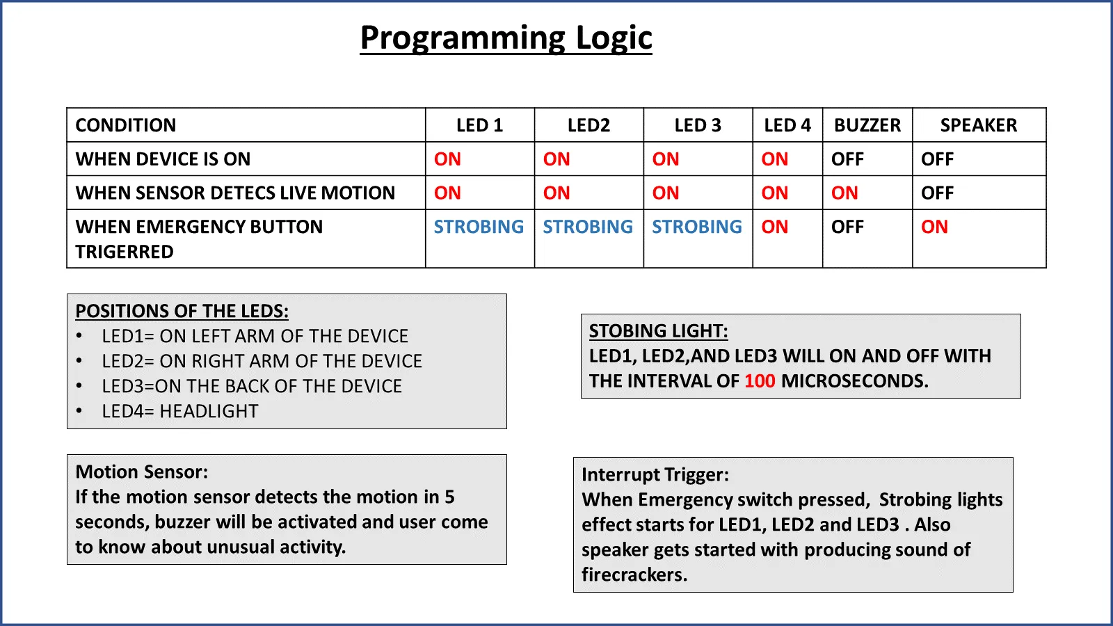
Programming
The programming of the microcontroller was not that complex because I wanted to use simple logic
to operate the device.
To distract the wild animal device will follow the following sequence.
1. When the Device power is ON, All LEDs should be ON, So proper illumination takes place
for the Farmer to work on the farm and can view wild animals from a long distance.
2. PIR motion sensor mounted on the back of the device will detect any movent of Wild
animals from the back of the Farmer and will alert him with the buzzer.
3. When a farmer detects any unusual activity from front or behind, he can trigger an
emergency switch which will produce a strobe light effect of LED lights mounted on the from and
back strips of the device. And Speaker will produce the firecracker sound store in the SD card
of the MP3 decoding board. The motion sensor will stop sensing, and the buzzer will go off.
4. When the Emergency trigger is pressed again, strobing light will stop and illuminate as
usual, and Speaker will stop. Then motion sensor again starts sensing the live motion and gives
an alert through the buzzer.