Input Devices
Group assignment:
Probe an input device(s)'s analog and digital signals
Document your work to the group work page and reflect on your individual page what you learned
Individual assignment:
Measure something: add a sensor to a microcontroller board that you have designed and read
it.
Individual assignment:
Input devices play a vital role in the electronics system to sense the data and accordingly act
with the help of output devices. The human body has five primary senses, and accordingly, our
brain acts with the help of our body parts. Just like that, to sense the data and perform a
specific task required the input devices. There are several input devices just like Switches,
Sensors to measure temperature, pressure, humidity, and gases like oxygen, hydrogen, CO, CO2,
etc.,
This week, I will develop my final project board and use the same for the input devices
assignment.
PCB design
I/P and O/P devices required in the final project board.
I want to design a board that accommodates the following Input devices:
1. Motion sensor: To sense the wild animals trying to attack from the backside
2. Push Button: Emergency Switch to start Strobe light and Speaker
3. SD Card Module: To send the .mp3 file to the Bluetooth speaker.
4. GPS Module: To send live location during the Emergency condition for help. (Optional)
5. GSM Module: To send a message of GPS location in an emergency. (Optional)
Output Devices:
1. BUZZER: Small buzzer only person should be aware of wild animals available at the
backside, will sense using RCWL sensor.
2. LED Strobe Light: To distract the wild animal using a Strobe light.
3. Speaker: To distract wild animals using very Acute noises like Gun shoot noise.
Selection of the microcontroller
To add the following devices, I need to select a suitable microcontroller for this application. I
want to use a Bluetooth speaker for this device. So, I need to add the Bluetooth module for the
device. Also, in the next spiral, I want to add the camera and send the live images to the
server, which requires a wifi module.
For this, I have referred to the datasheet Atmega328P, ESP32. For ATmega, I need to add a
separate driver for the Bluetooth and Wifi. Instead of this ESP32, it has inbuilt Bluetooth and
wifi, so I have decided to use ESP32 for this project.
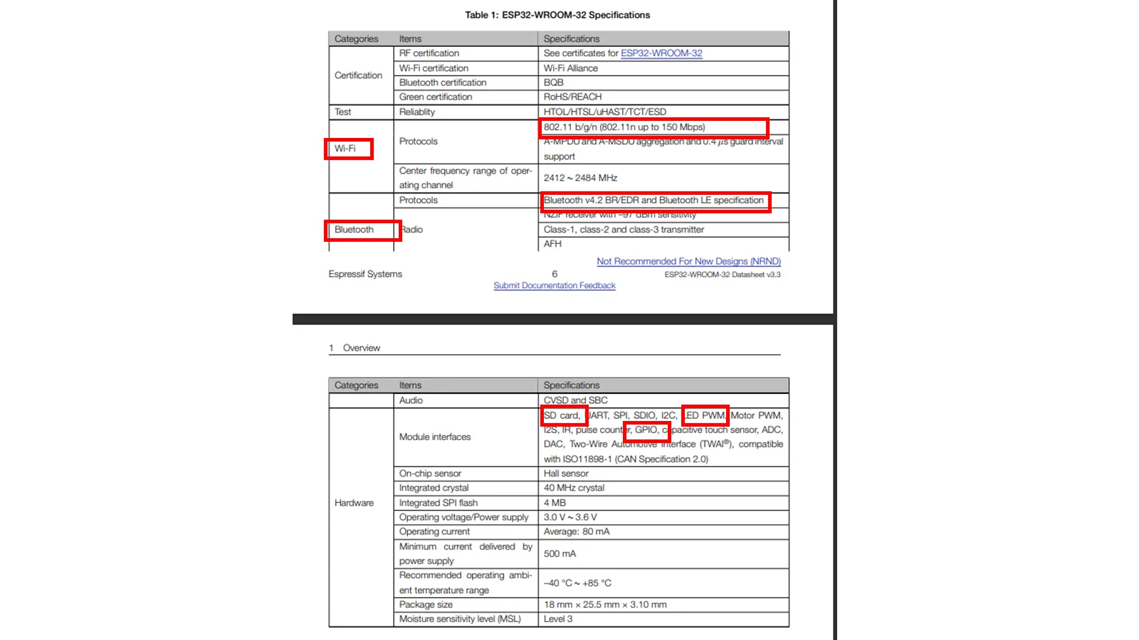
Some specifiations of the ESP32 board is shown below.
I referred to the pinout of the esp32 to select it for the input-output devices.
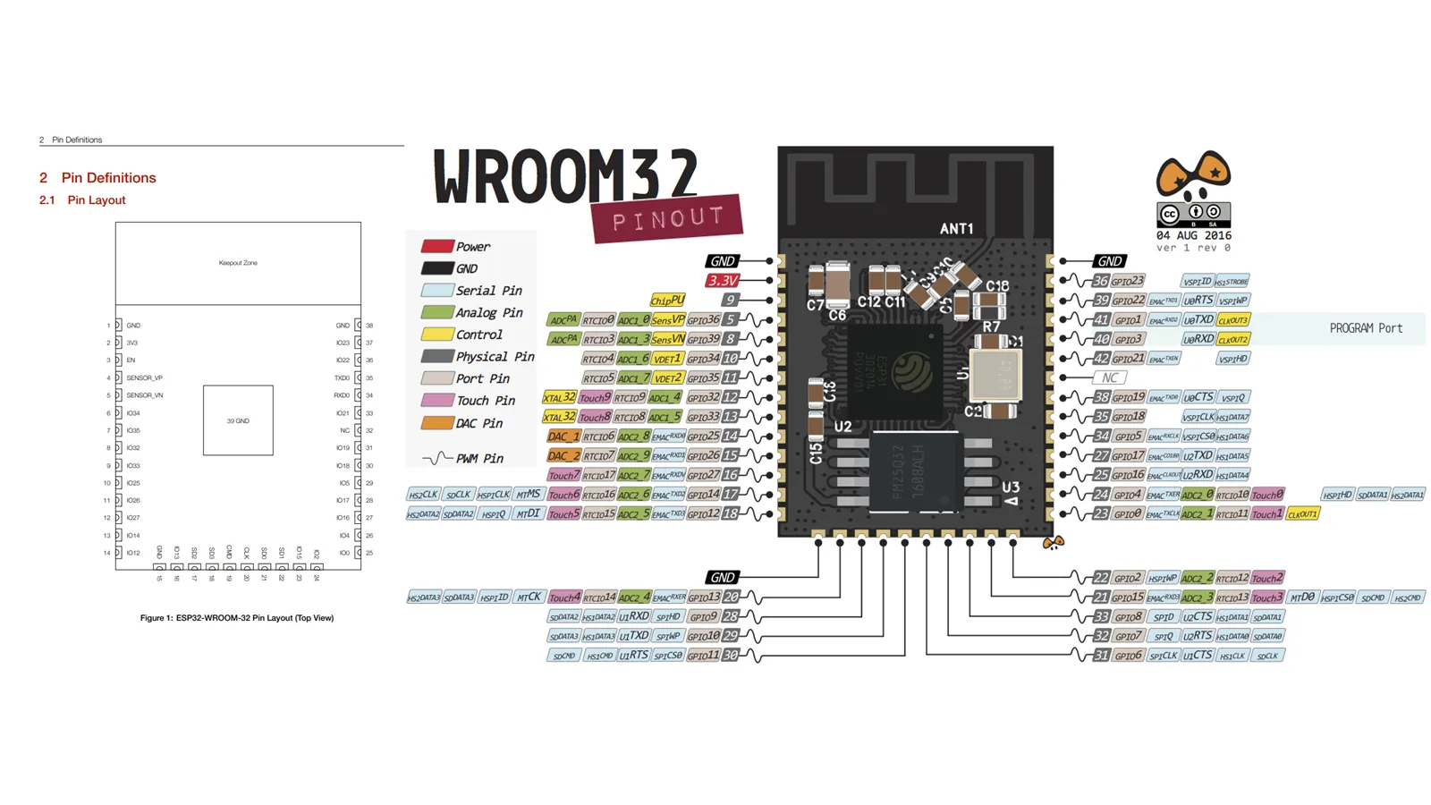
Details of the all the ports in the ESP32 Ic as shown below.
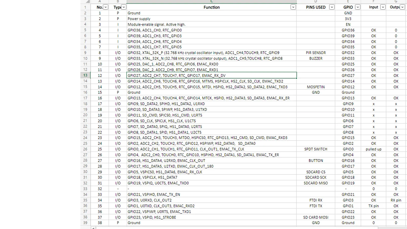
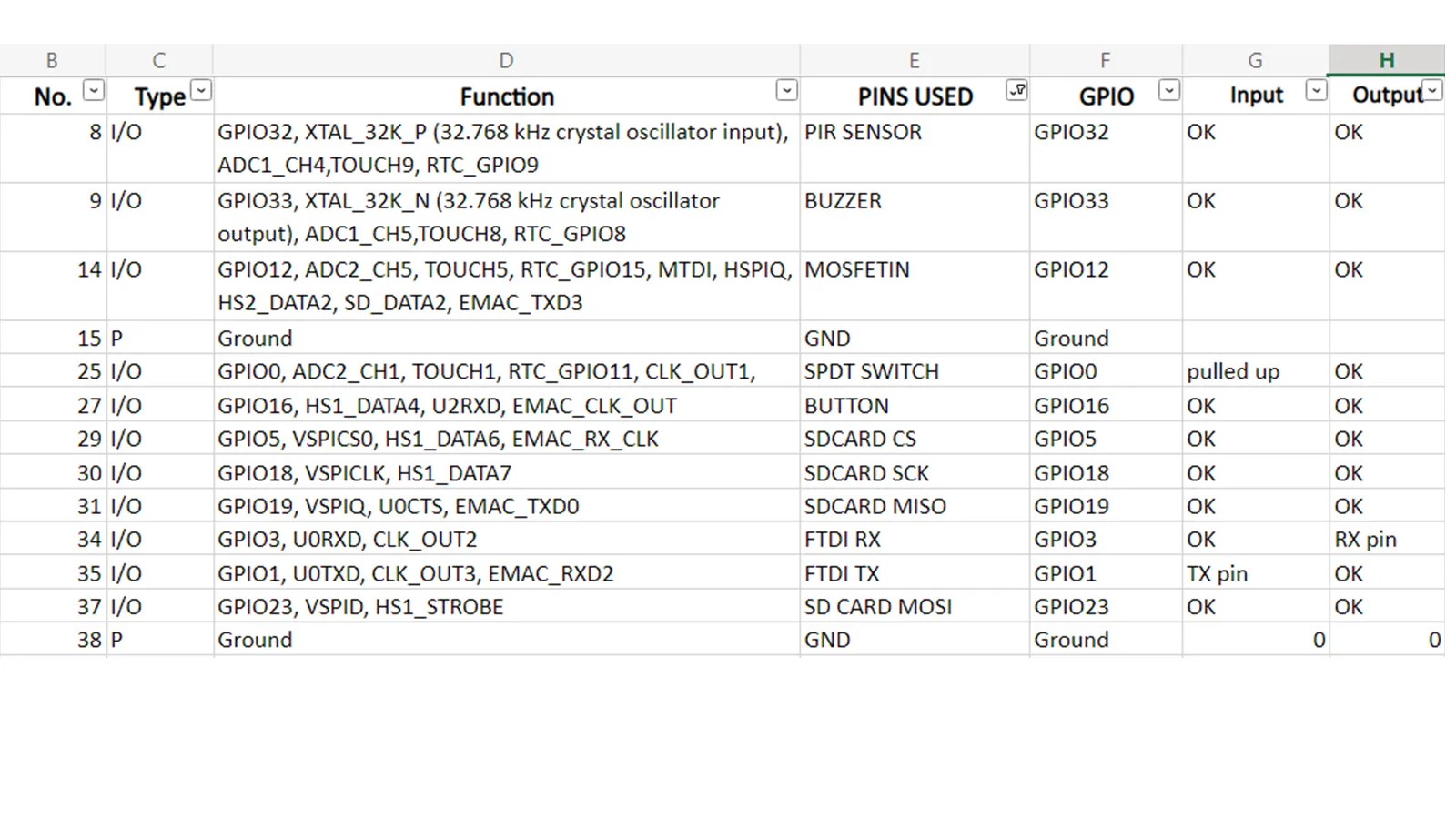
By referring Datasheet I have chosen following ports for the Input output devices.
After deciding the Microcontroller and Input output devices that I need to add, I have decided to do design the board for the Project.
PCB design
To design the PCB in the Eagle software, I will require an ESP32 library, which is not available
in the Eagle library manager.
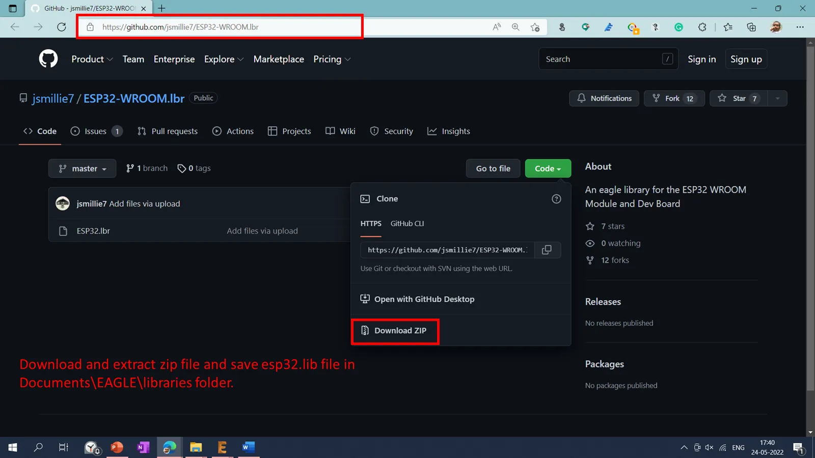
To design the board using the ESP32 microcontroller in Eagle, I have downloaded the esp32
library using the following link ESP32
Library .
After downloading the library, it is saved in a documents-Eagle-Library folder.
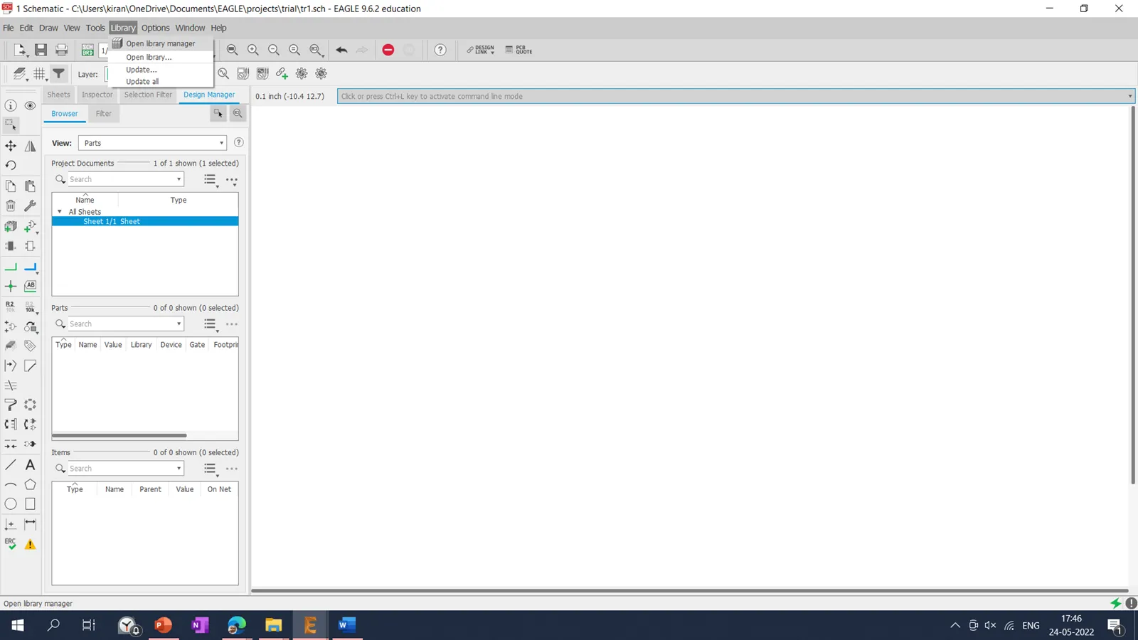
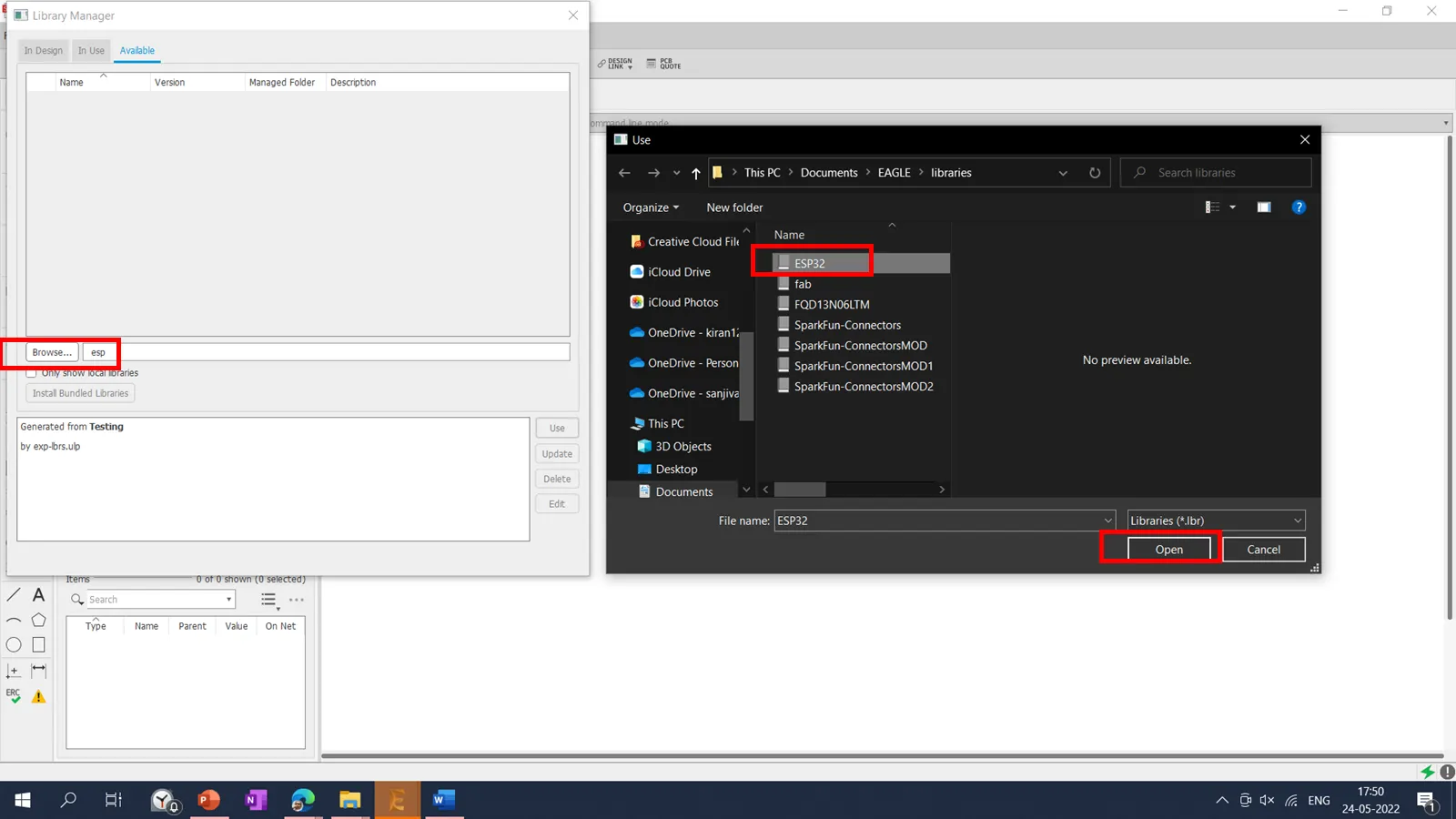
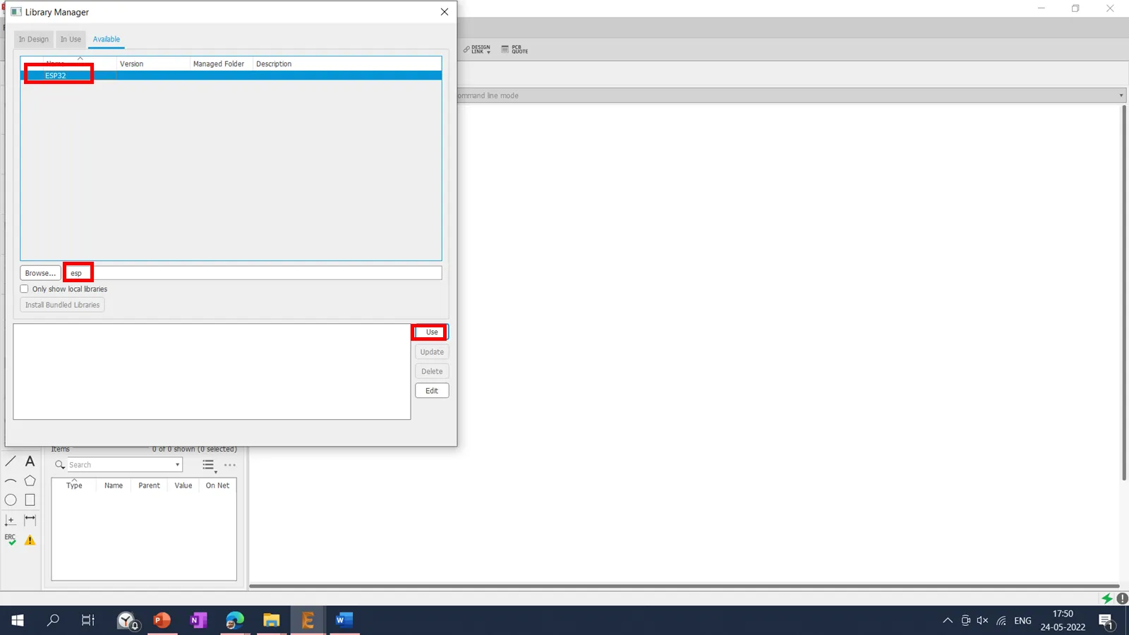
Then I have added library into the project using Library Manager.
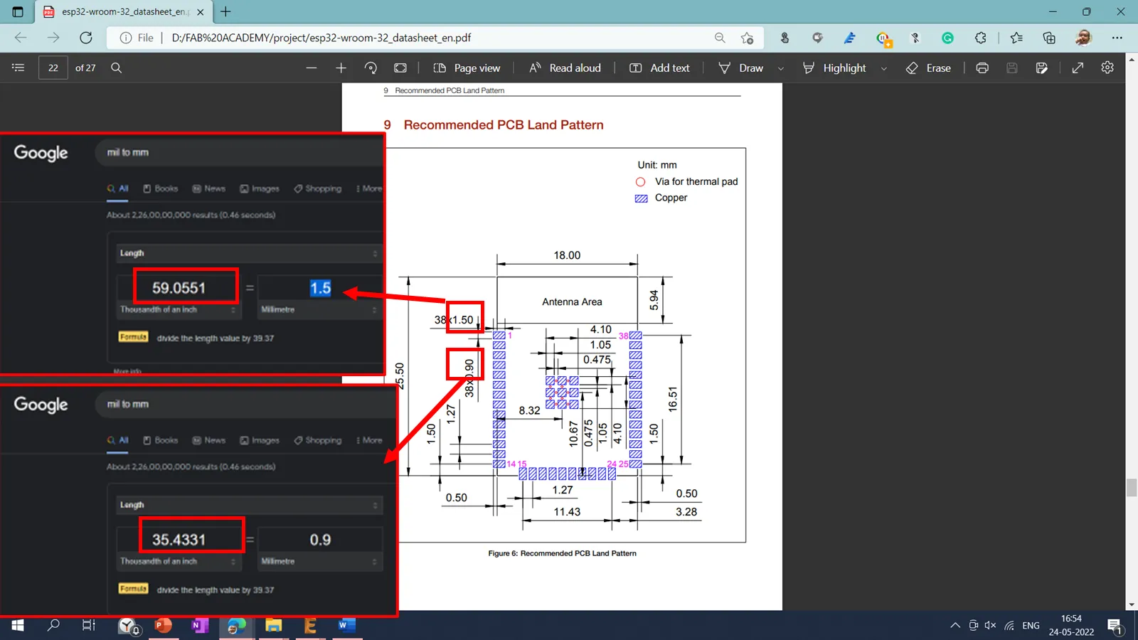
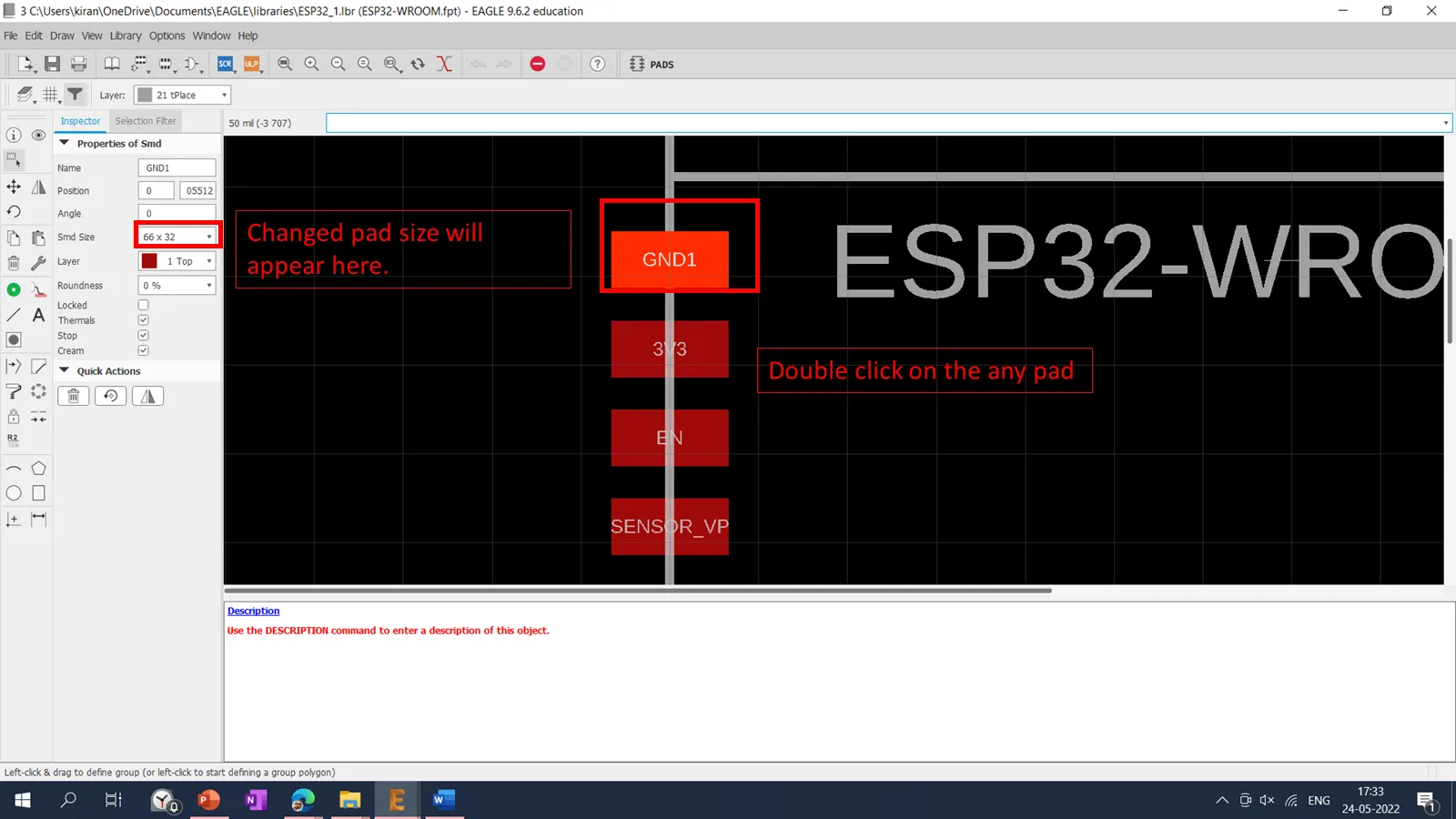
After reading the datasheet of ESP32, the standard pad size for the microcontroller pads was mentioned. Then I changed the pad size of ESP32 using the following procedure.
Following process was followed to change the pad size. I we cant change the pad size, we cant do machine the pad using milling machine. Hence it is important to change the pad size. .
Go to the Library manager
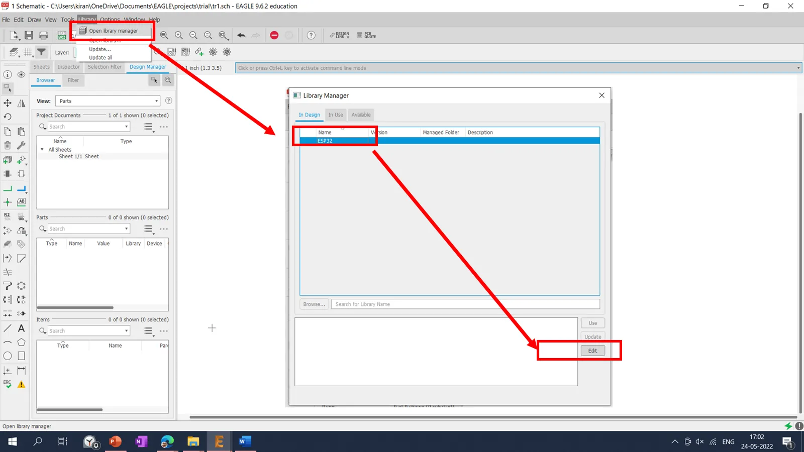
elect the esp32 library and click on the Edit
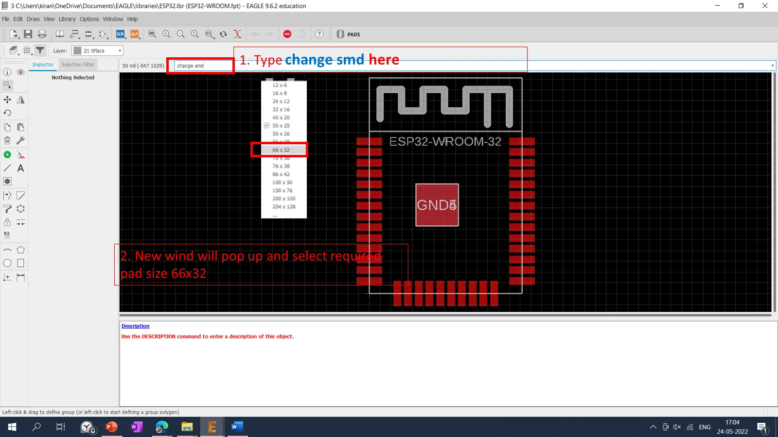
If wee double click on the any pad we can see the current pad size it s 118x35 mill and recommended size is of 66x32 mill
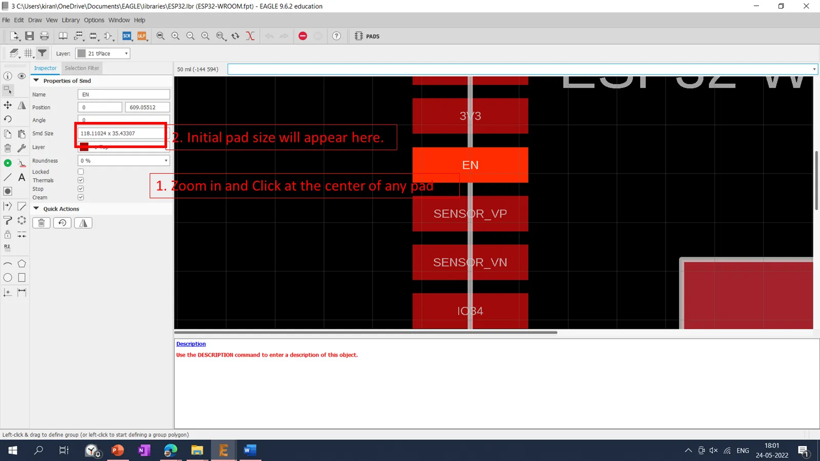
Then type "change smd" command in command prompt, new window will popup and select the required 66x32 mill.
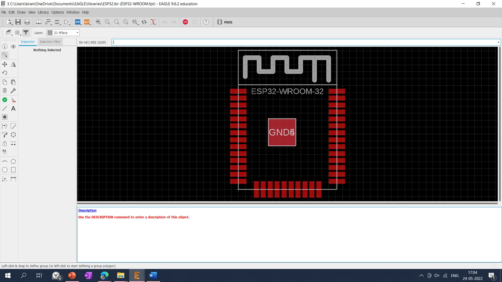
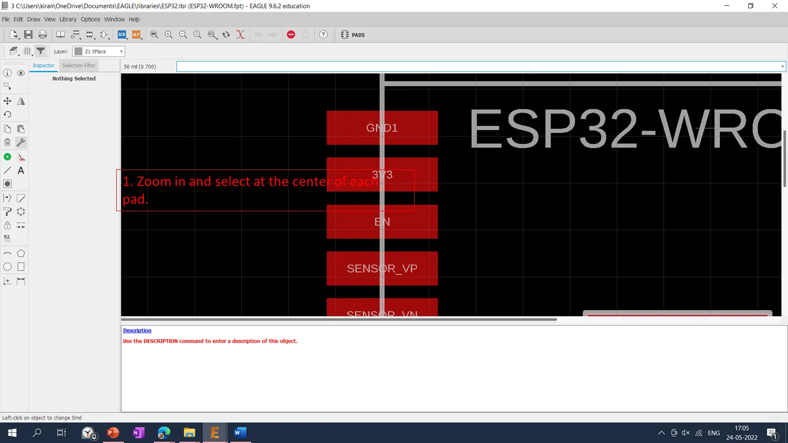
After selecting 66x32, then clicked on the each pad individually to change the size.
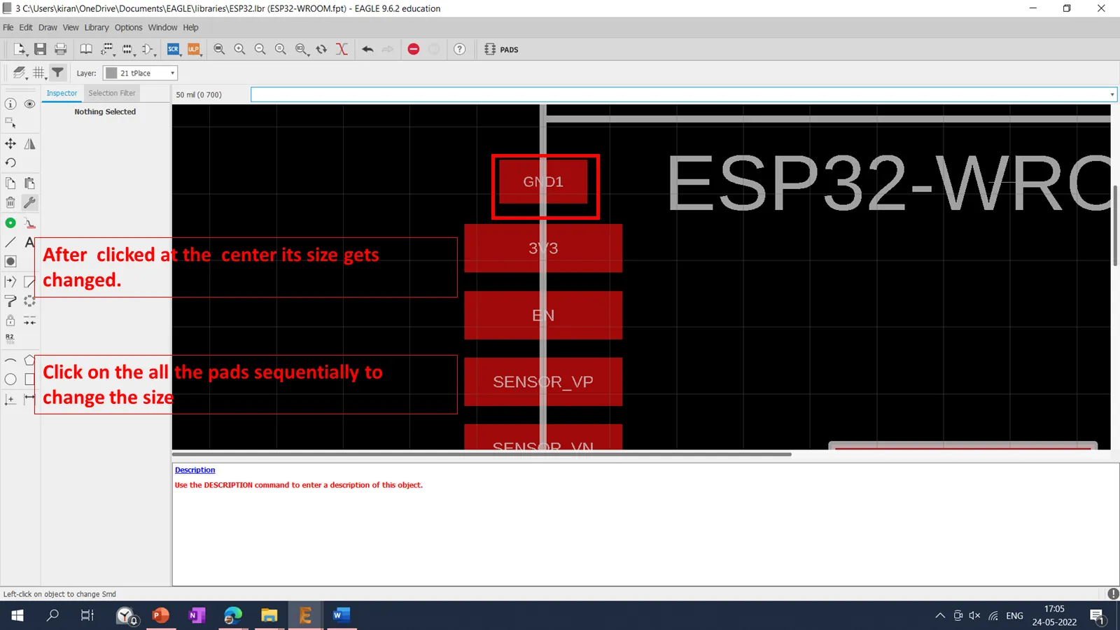
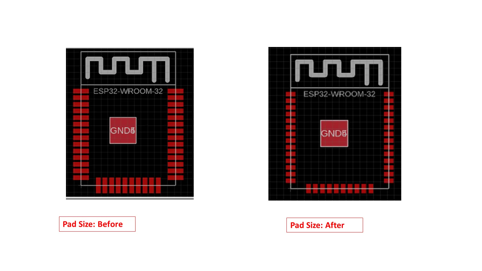
You can observed change in the size of the pads before and after the modification.
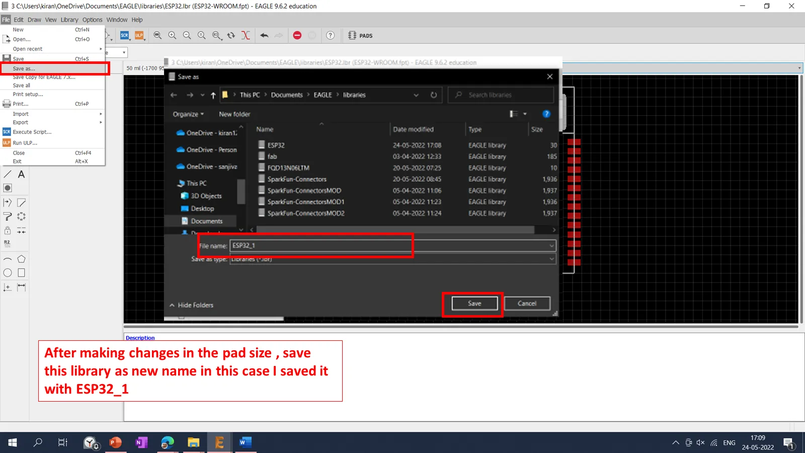
Then save as this library with the new name say esp32_1. An we need to save the file in the same folder.
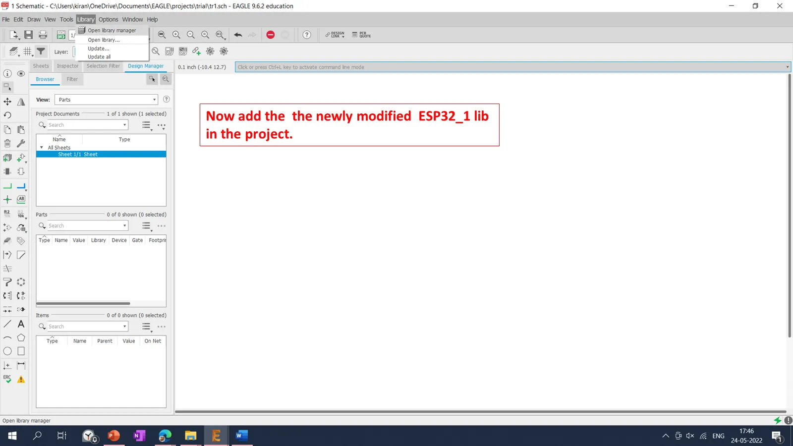
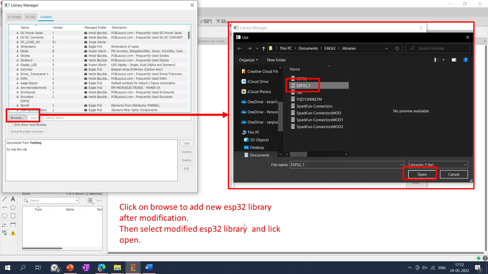
Then we need to add the modified library into the library manager.
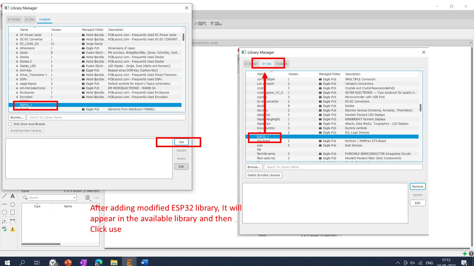
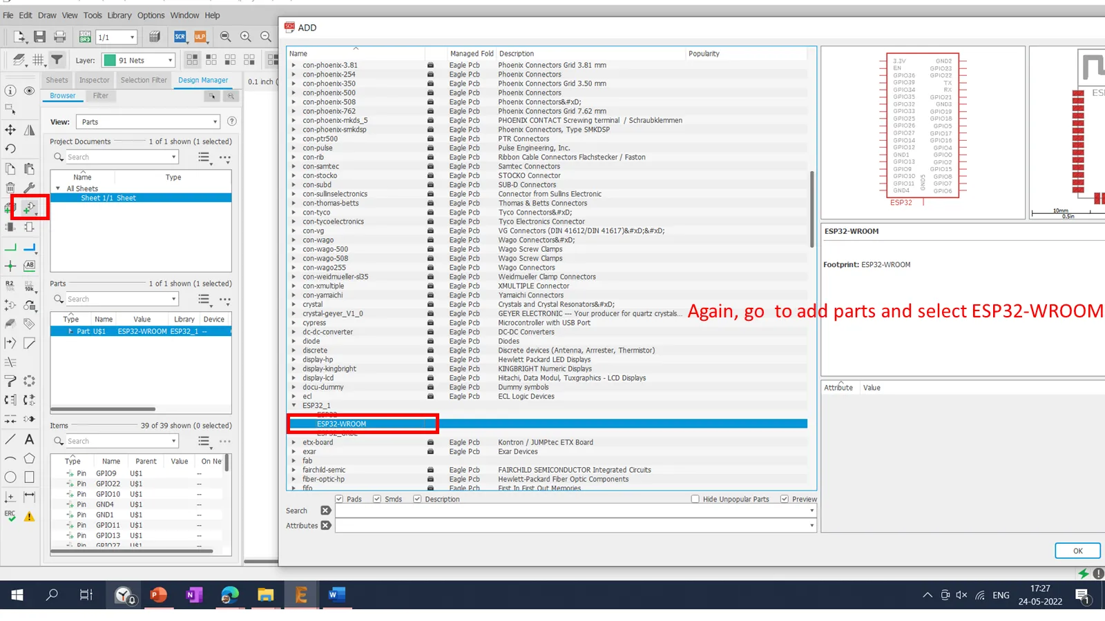
Then we need to add the esp32-wroom component by using add feature into the schematic shown below.
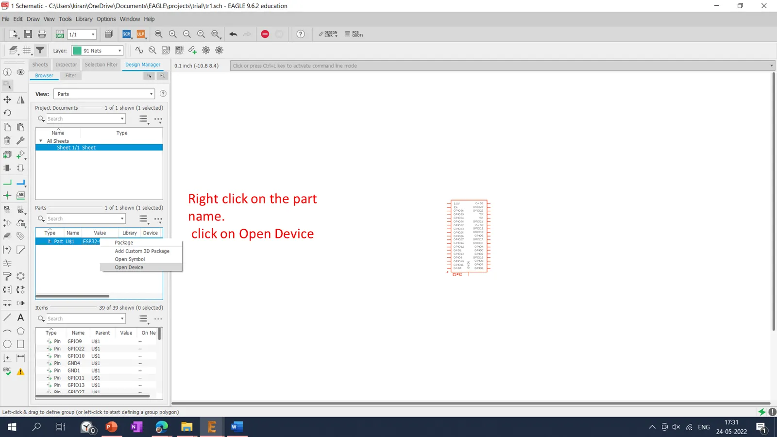
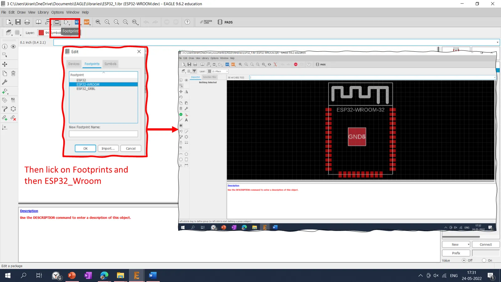
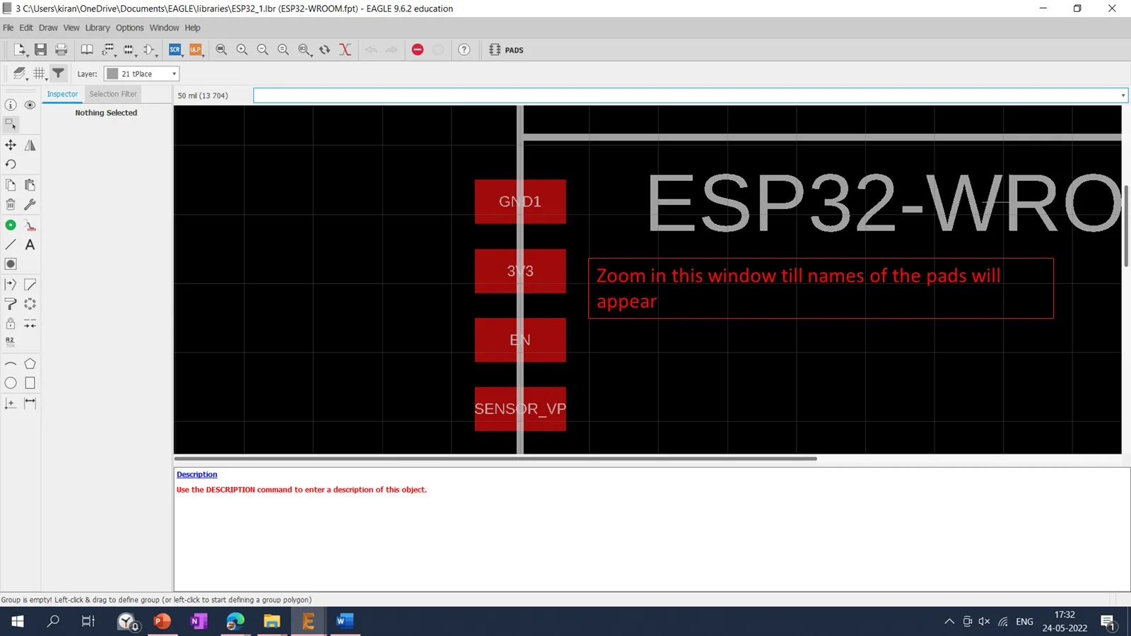
To check the modified pads appeared in the design we need follow this procedure.
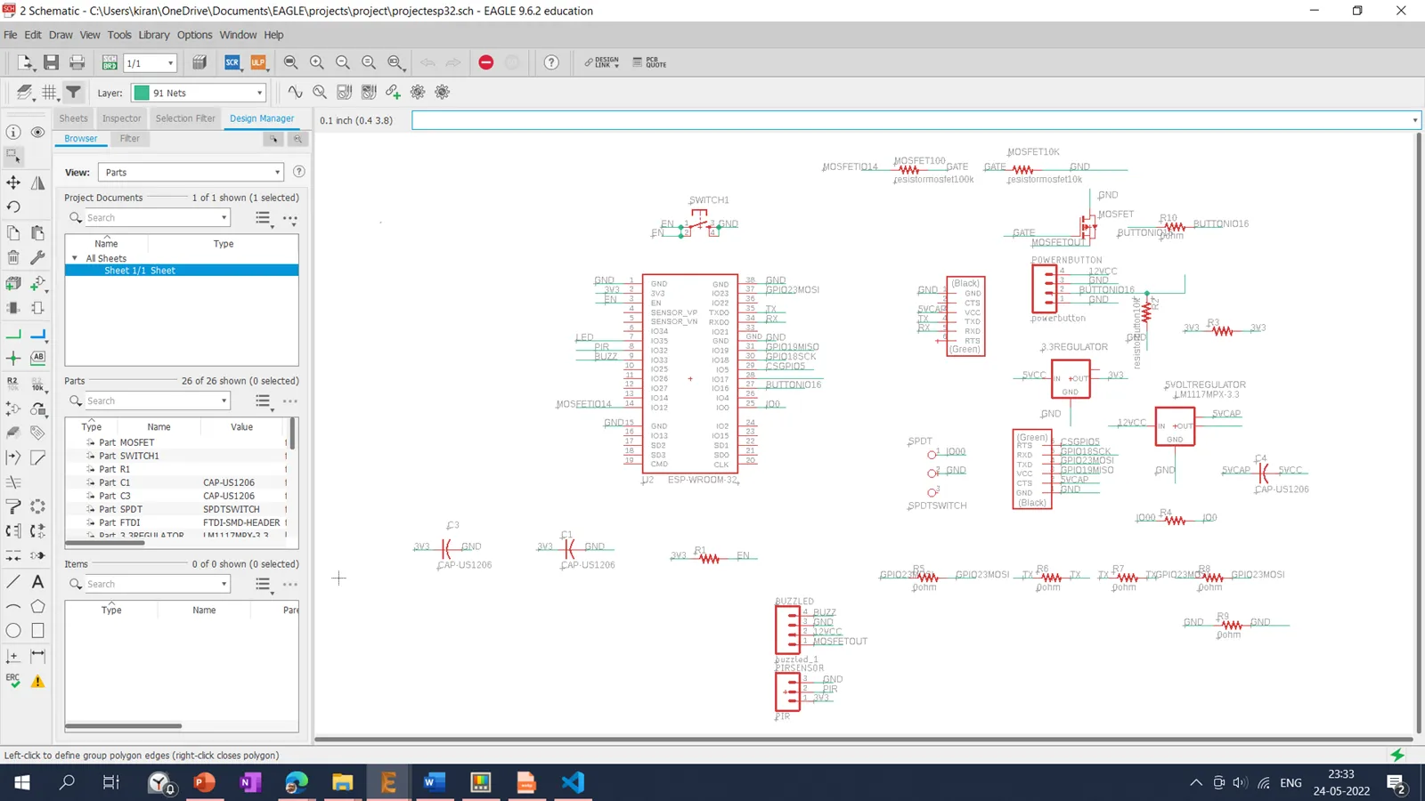
After finalization of the EPS32 library I started to add the different components in the Schematics. I have referred the initial schematic given by Prof. Neil.in the Embedded programming ESP32 Board. For different connectors used in the board, I have downloaded SparkFun connectors libraries using the SparkFun-Connectors Library. Also added the Transistor library downloaded using the link transistors-lm1117 library.
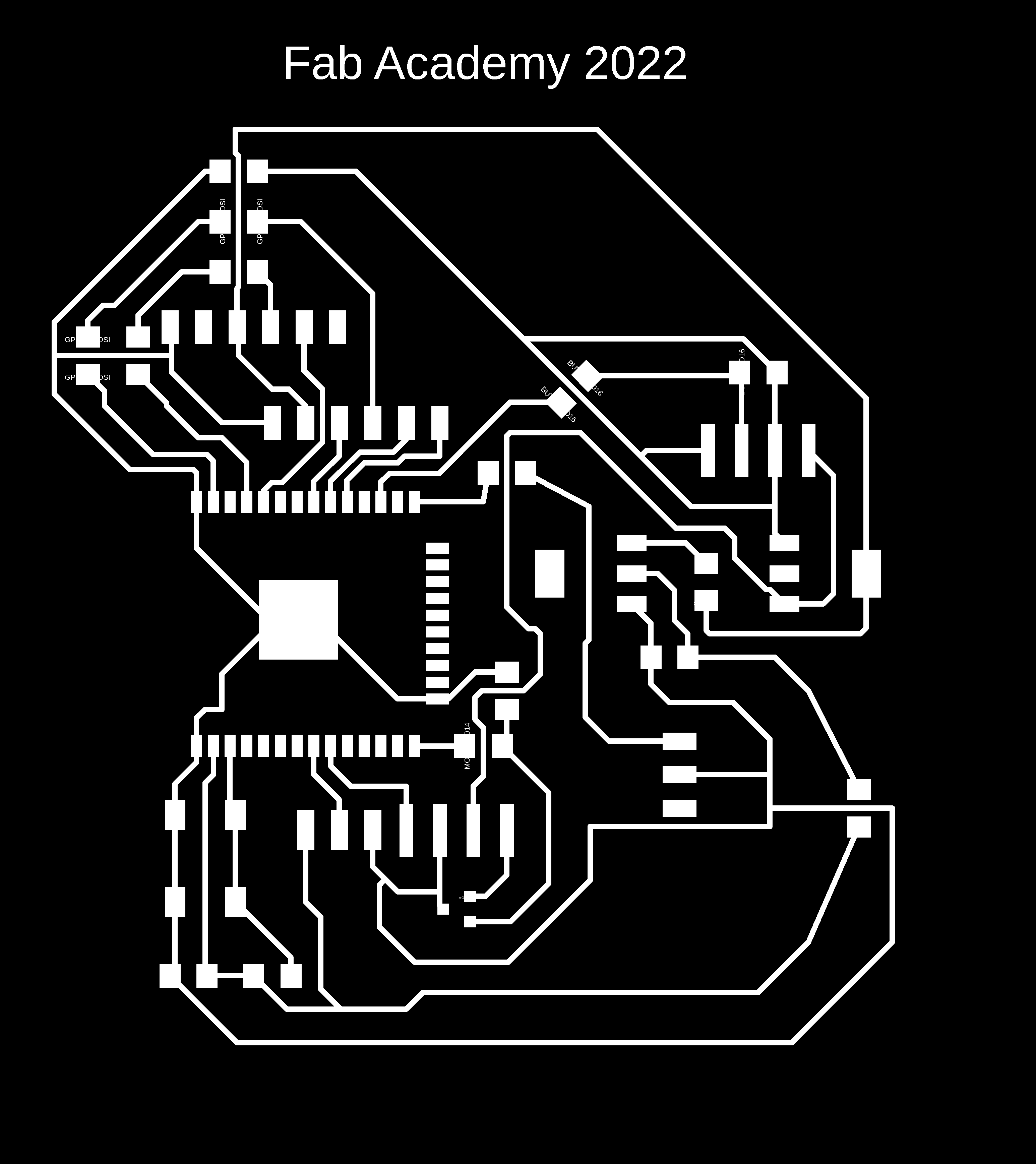
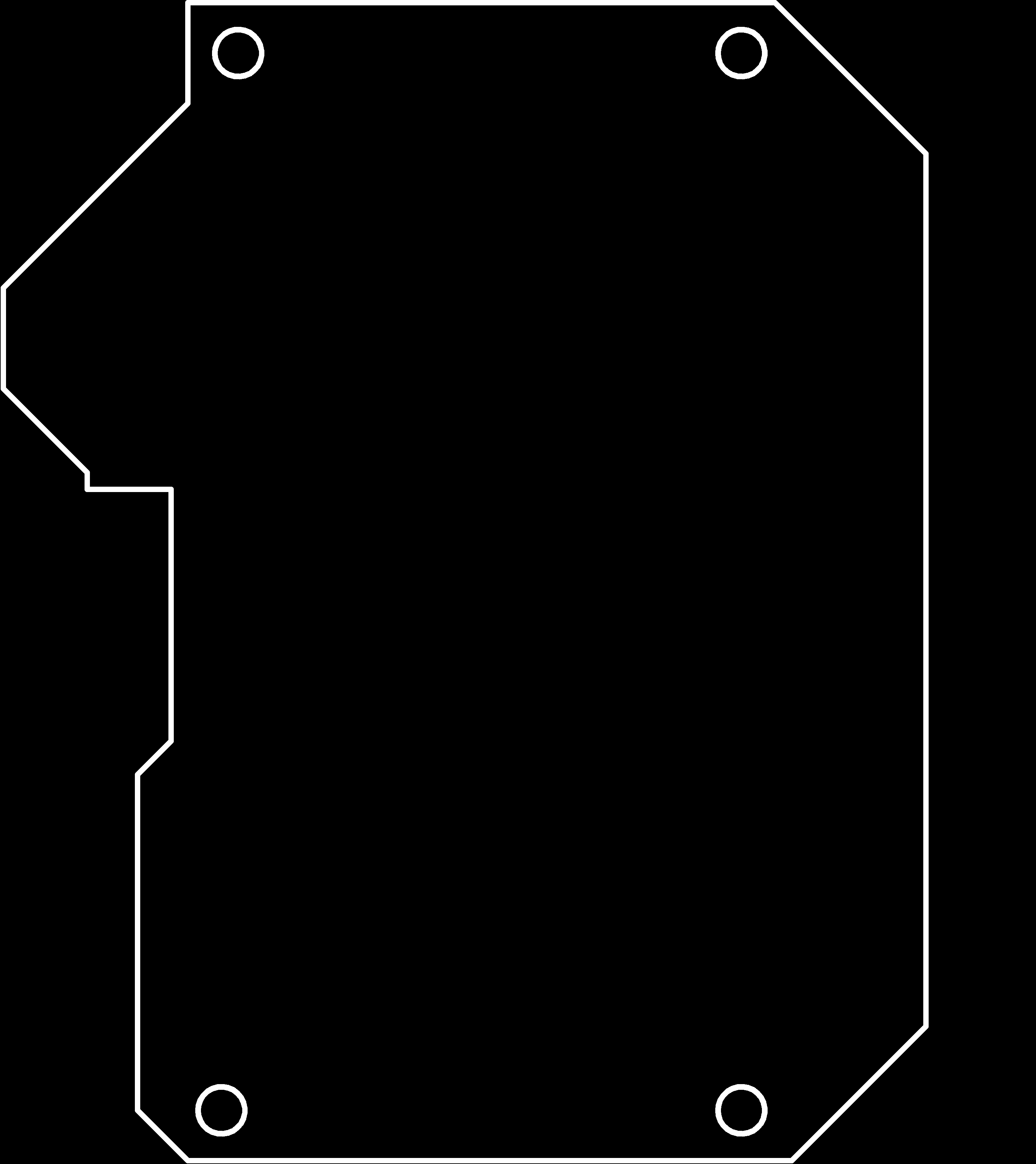
Final Board design of the projet is shown below.
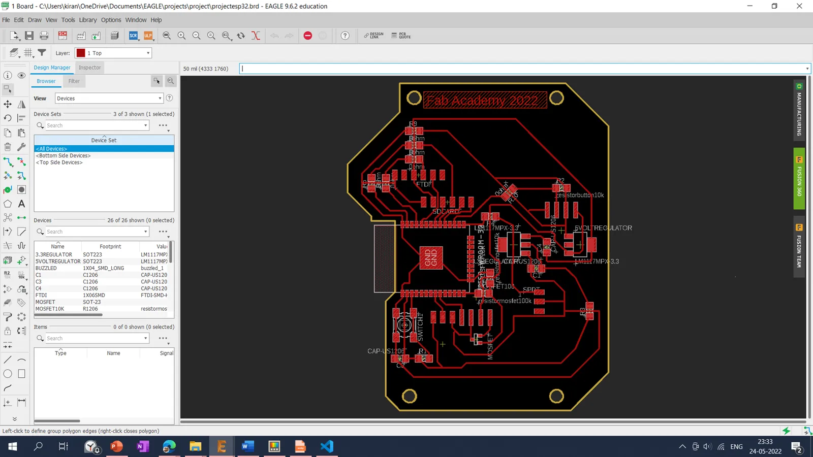
After finalizing the board,traces were selected using top layer and exported into a .png monochrome file with 1000 dpi resolution. In the same way, the interior is selected using the dimension layer and exported into a .png monochrome file with 1000 dpi.
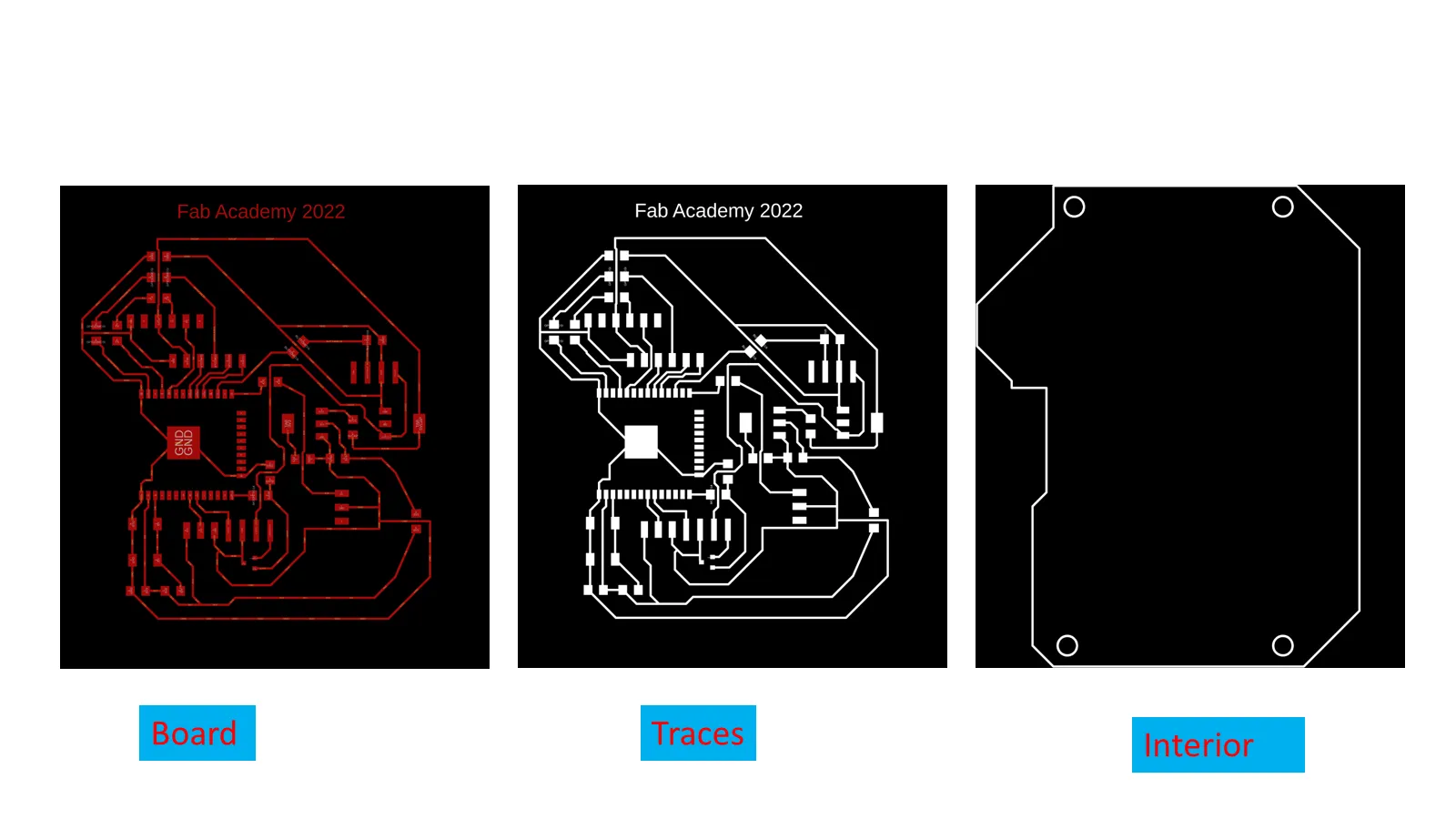
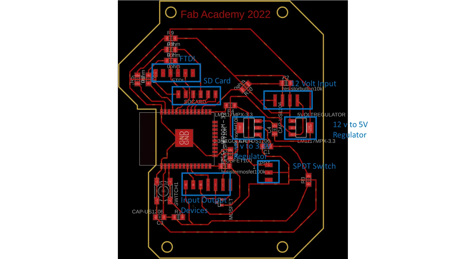
Placement of different components on the board is shown below.
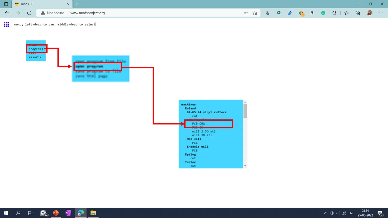
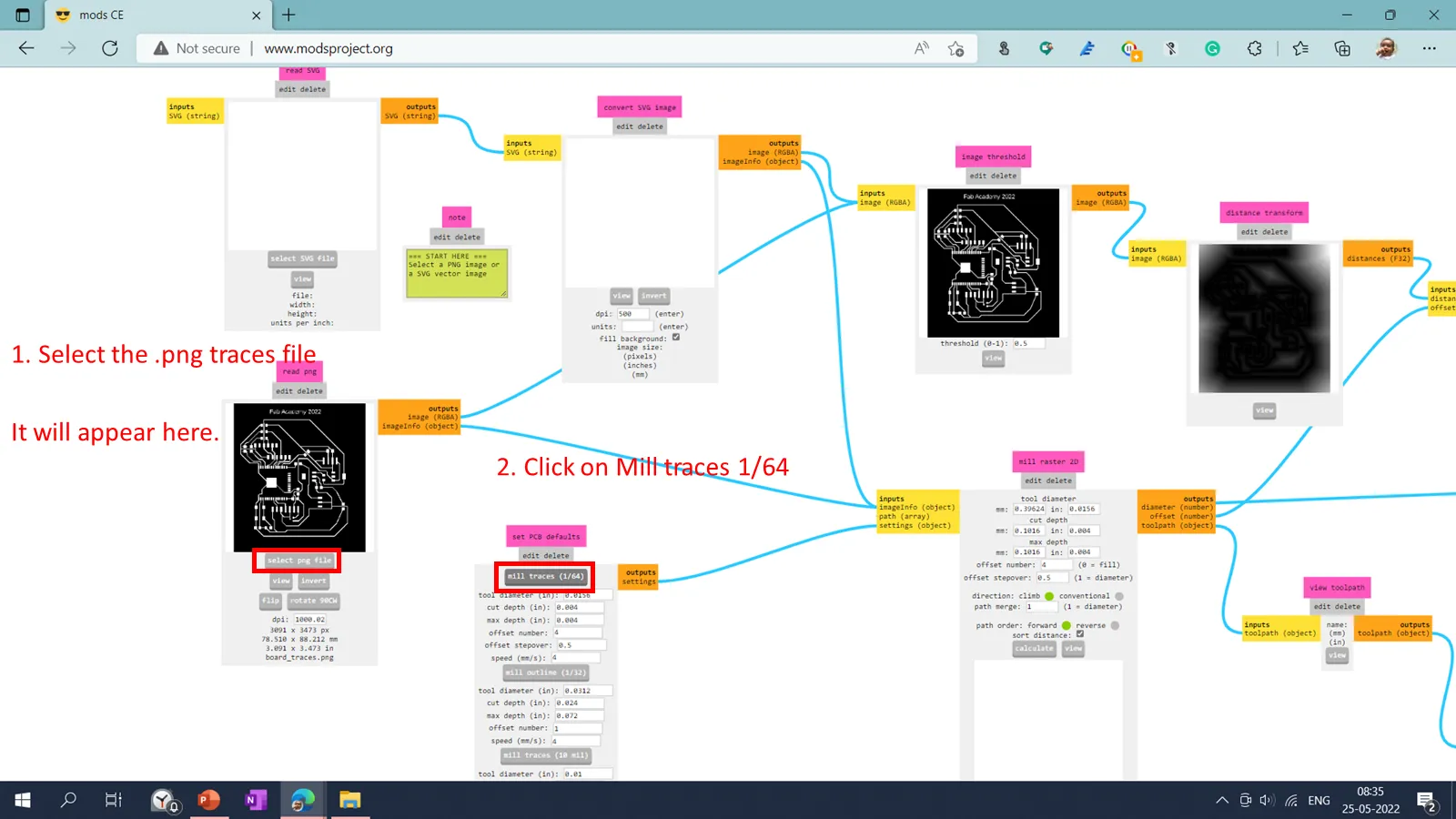
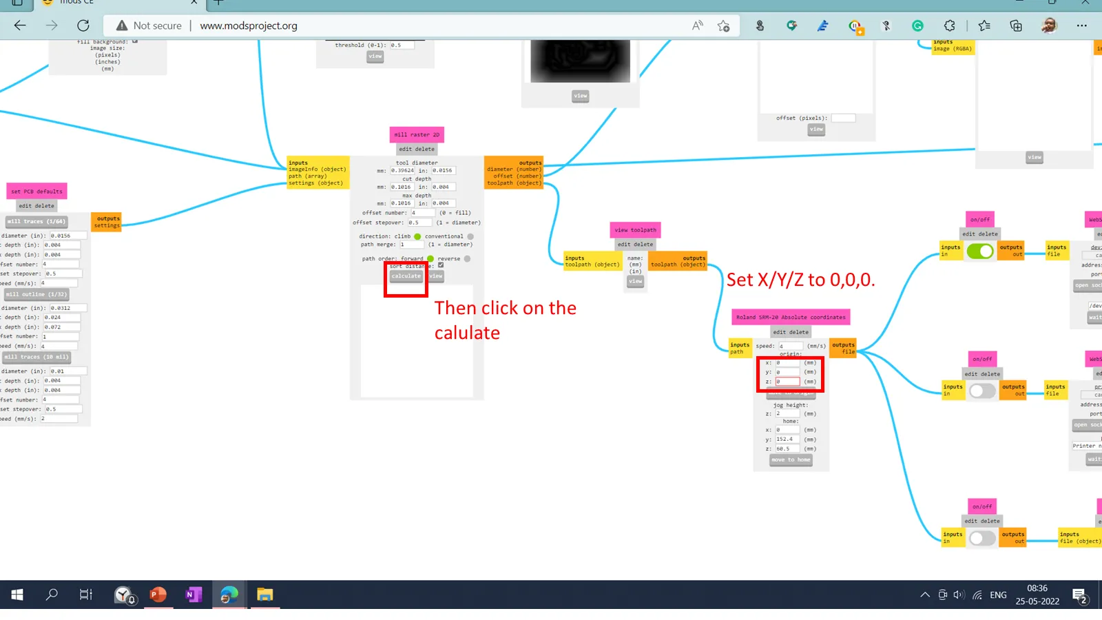
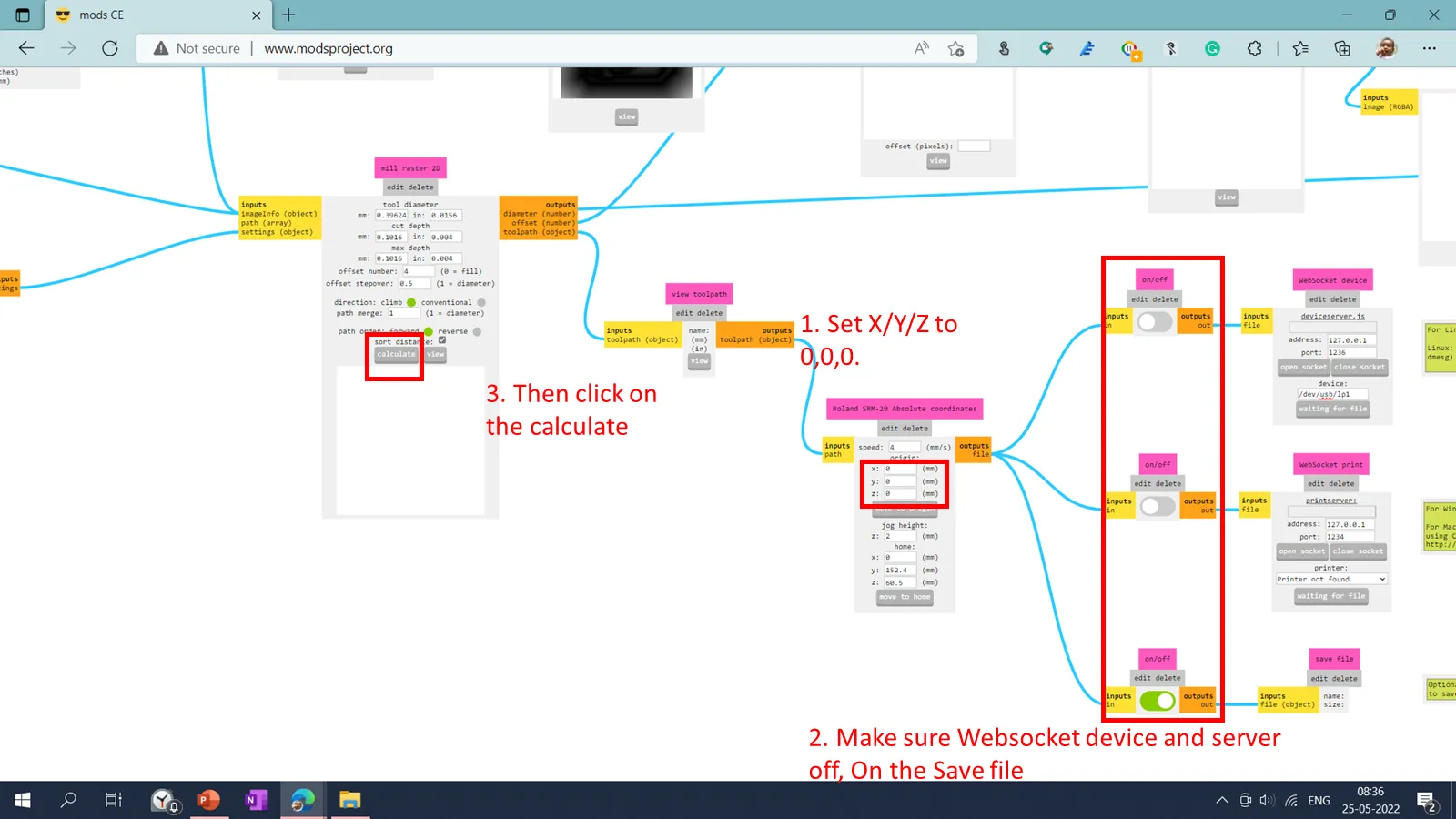
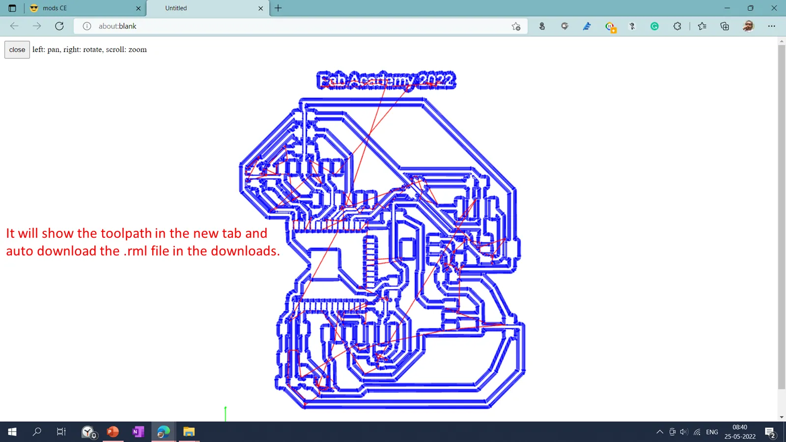
Tool Path Generation
I have used modproject http://www.modsproject.org/ tool for the tool path generation. I have imported traces and the interior .png file into the mods project and selected the 1/64 tool for the traces and 1/32 for the interior.
Machining and soldering
After downloading, the .rml file from the modsproject file is imported into the SRM20 PCB milling machine. PCB plate fixed in the bed and V shape tool is mounted in the collet and set tool home position using drop test. Then I imported the .rlm file into the Vpanel for SRM20. And start the cutting operation.
.webp)
After finalization of the machining I have done the soldering of components on the PCB Board.
.webp)
List of the components used.
1. Resistor: 10K- 1 Qty
2. Capacitor: 1uF- 2 Qty
3. Capacitor: 10uF- 2 Qty
4. Capacitor: 0.1uF- 1 Qty
5. Push button (No)- 1 Qty
6. Sliding switch- 1 Qty
7. 3.3v voltage regulator (SMD)- 1 Qty
8. Microprocessor ESP32 Wroom- 1 Qty
9. FTDI Pin (6pin)- 1 QTY
10. 4x1 make header pins
11.5V Voltage Regulator: 1 Qty
12. Resistor: 0K- 7 Qty
13.FQD13N06LTM N-Channel Power MOSFET: 1 Qty
Input Devices
This week, I have decided to use PIR and Radar sensors as input devices.
I want to detect wild animals attacking from the backside in my project. In my wearable device,
I will add the sensor at the back, and so I will come to whether a living object is at my
backside. I learned about the PIR and Radar RCWL sensors by searching different sensors.
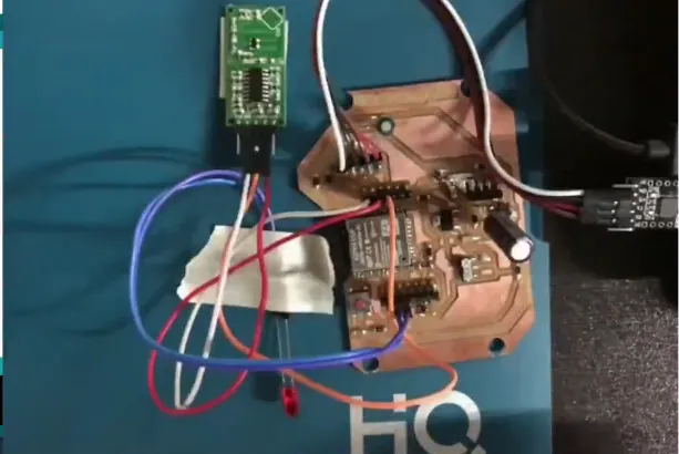
This week, I will use the final project board for the input devices assignment.
I have connected Sensor signal pin to the GPIO19 and addition LED is connected to the
GPIO33. When The any motion detected this by Sensors board will send the signals to glow
LED.
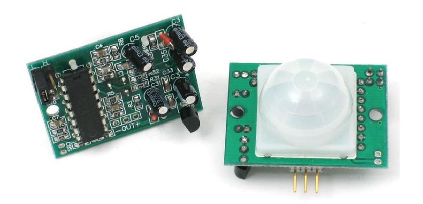
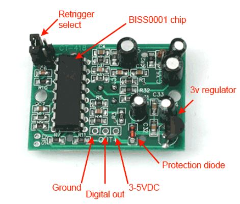
PIR Sensor
PIR is an acronym for Passive Infrared sensor. It is an inexpensive sensor capable of detecting the presence of humans or animals. As indicated in the diagram, this HC-SR501 PIR sensor module has three output pins: Vcc, Output, and Ground. Since the output pin is 3.3V TTL logic, it is compatible with various platforms, such as Arduino, Raspberry, PIC, ARM, 8051, etc.
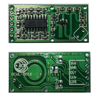
Radar Sensor
The RCWL-0516 Microwave Radar Sensor module is an excellent substitute for PIR motion sensors.
This sensor detects only motion within its detection range.
This sensor detects moving objects using "microwave Doppler radar." The device's sensitivity
range is 7 meters. Upon activation, its TTL-level output (OUT) pin will transition from LOW (0
V) to HIGH (3.3 V) for a limited amount of time (2 to 3 s) before reverting to its idle (LOW)
state.
This modular sensor module can be utilized with various microcontroller or even without a
microcontroller. It can accept power supply sources between 4 and 28 V.
The output pin can be used for various purposes, including driving an audible/visual
indicator and connecting to the I/O of any 3-V microcontroller for further processing. Avoid
placing any metal components in front of the sensor module during assembly. Additionally, always
maintain at least 1 cm of open space on the front and back of the module.
Comparison of PIR and RCWL sensor.
PIR detectors detect movement by measuring a person's black body radiation and are ideal for applications that require a certain detection pattern, such as a walkway. For optimal coverage, the PIR sensor must be in the right spot and at the right angle, and an attacker can simply fool it. Microwave sensors are effective across broad areas. Microwave is more sensitive than PIR. Trees swinging in the wind might trigger false alarms. Detects motion through thin walls, plastic, and glass. Most PIR sensors are affected by temperature. PIR sensor sensitivity is affected by ambient temperatures above 35°C. Microwave sensors work more consistently between -20°C and 45°C. Microwave sensors outlast PIR sensors by 100,000 hours.
DHT11
DHT11 is a device that measures humidity and temperature in its environment. It keeps track of the
temperature and humidity in a certain area. It consists of a resistive type humidity sensor and
an NTC (negative temperature co-efficient) temperature sensor. An 8-bit microcontroller is also
included. The microcontroller performs ADC (analogue to digital conversion) and outputs a
digital signal through the single wire protocol.
The DHT11 sensor can measure humidity from 20% to 90% with +5% precision (RH or relative
humidity), and temperature from 0 to 50 degrees Celsius with +-2C accuracy.
DHT11 sensors can also be utilized to create a wired sensor system with up to 20 metres of
cable.
DHT11
Datasheet
Group assignment:
Group Assignment Link
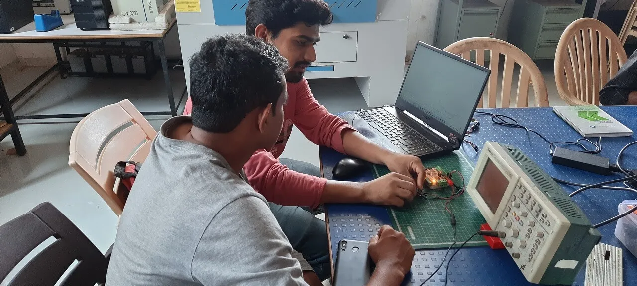
This assignment involves describing what we learnt during Input Devices week, which includes gaining an understanding of various sensors and probing an input device's analogue levels and digital signals on one of the boards we constructed as part of our individual assignment for this week.
Objectives of the Group Assignment:
- Probe an input device's analog levels and digital signals
Input Devices used
- IR sensor
- Potentiometer
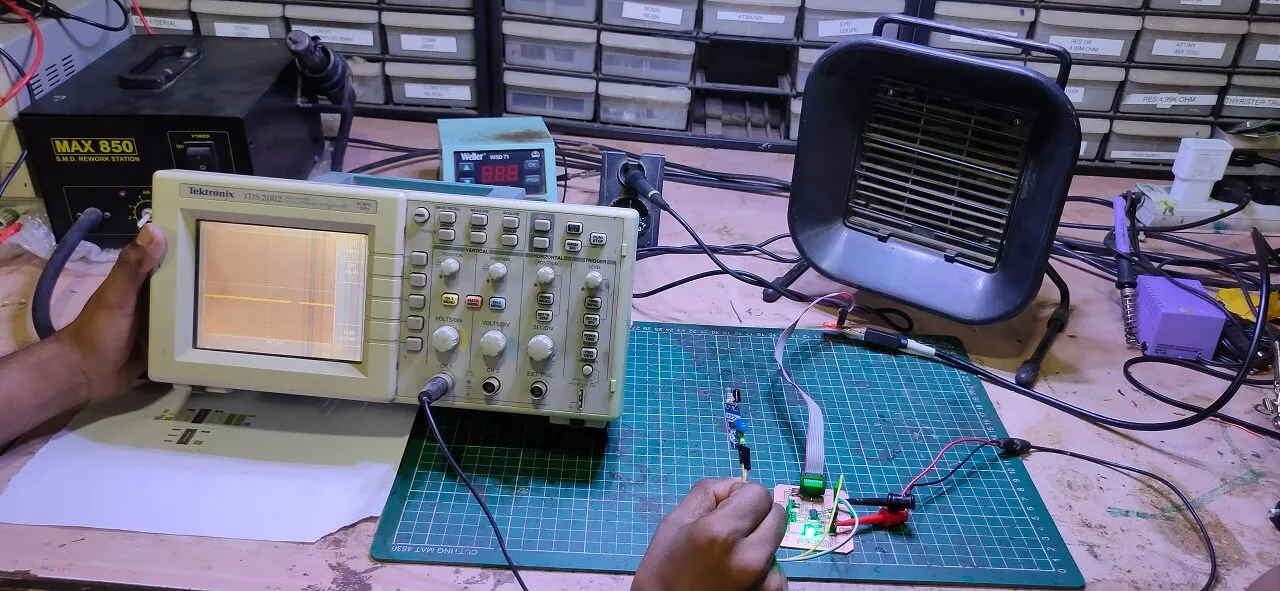
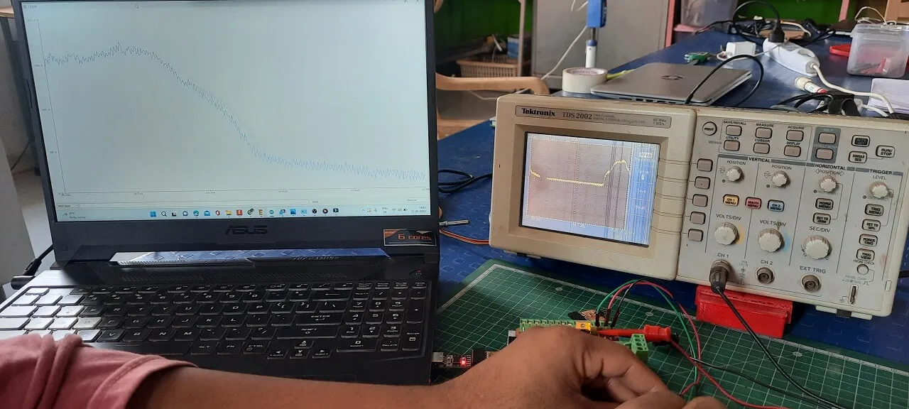
After programming the board with Arduino IDE, we connected an IR sensor to the Input devices board and triggered the sensor in order to examine the digital signal of an input device. As illustrated below, we first attached the board to a DSO (Digital storage oscilloscope) and explored the sensor's digital waves.
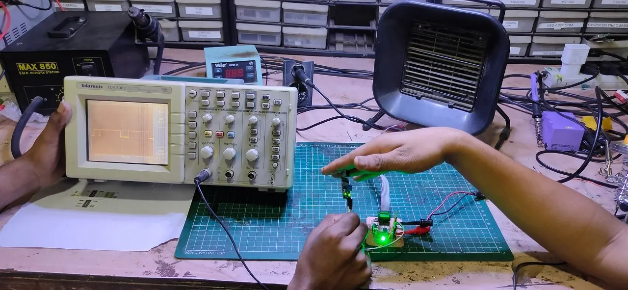
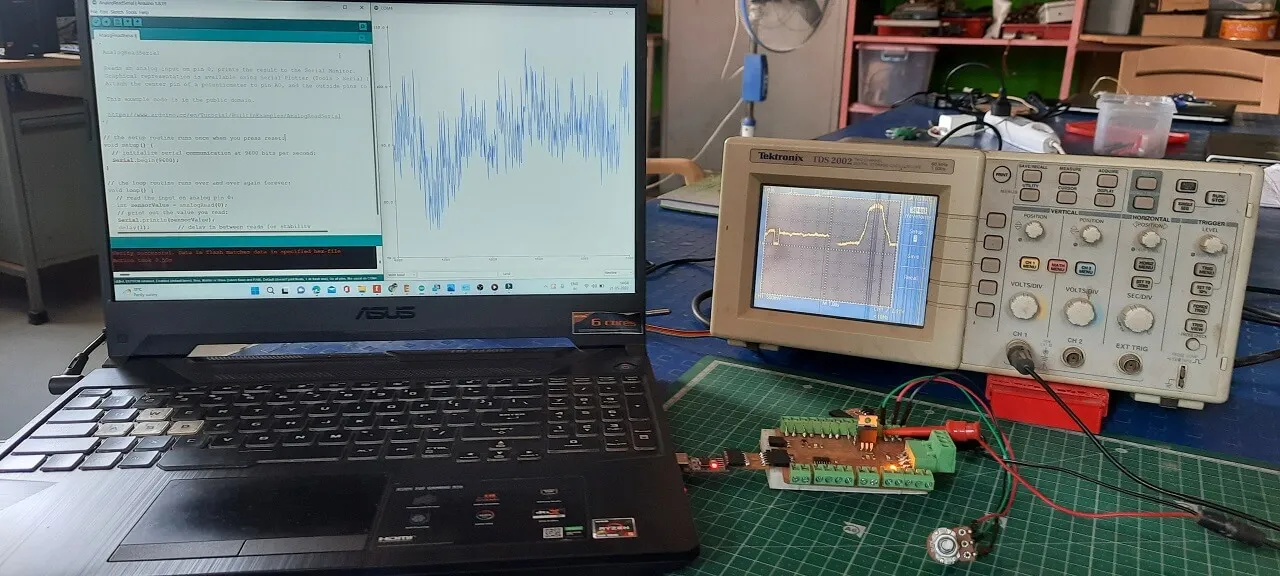
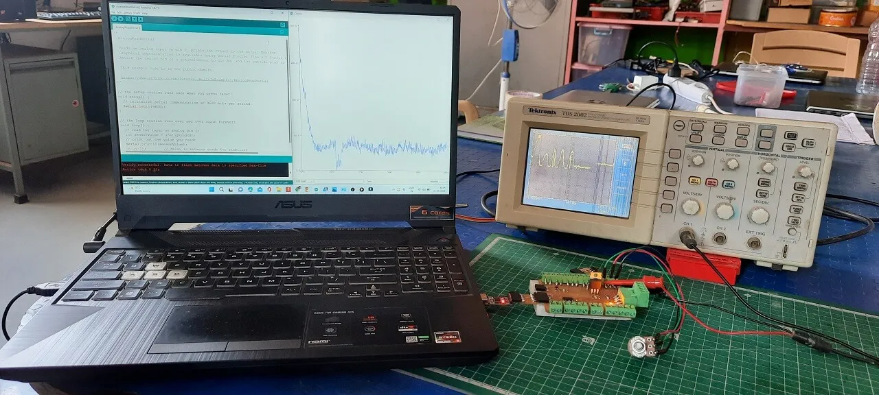
We connected a potentiometer to the Input devices board and programmed the board for analogue read using the Arduino IDE later to explore the analogue values of an input device. Then, as shown below, we connected the board to a DSO (Digital Storage Oscilloscope) and investigated the sensor's analogue levels waves.
Downloads
Program files
Checklist
-
Linked to the group assignment page
-
Documented what you learned from interfacing an
input device(s) to microcontroller and how the physical property relates to the measured
results
-
Explained the programming process/es you used
-
Outlined problems and how you fixed them
-
Included original design files and source code
-
Included a ‘hero shot/video’ of your board
Linked to the group assignment page
Documented what you learned from interfacing an input device(s) to microcontroller and how the physical property relates to the measured results
Explained the programming process/es you used
Outlined problems and how you fixed them
Included original design files and source code
Included a ‘hero shot/video’ of your board