Mechanical Design, Machine Design
Maslow CNC Machine
Maslow is a large (4'x8') CNC cutting machine designed to let you cut big, useful things out of wood and other flat materials. Cut out a tiny house, a kayak, a tree house, some furniture, or anything else you can imagine. Maslow is designed to be affordable to buy, cheap to ship, easy to use, and powerful. Because designs can be shared digitally, you can build on the work of others or create your own from scratch. . 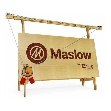
Maslow CNC group project is available
here .
Planning
For the development of this OPEN SOURCE type project, a planning consisting of 3 stages was made:
1. The plans for the structure that will support the MASLOW CNC were designed. The material that is needed has to have a certain resistance and hardness due to the weight that it is going to support. The structure will have the complete measurement indicated by the MASLOW CNC community, which is equivalent to the complete MDF plate of 122x244cms. Therefore adequate space must be considered to house those dimensions.
2. Design of the mechanism that will allow the movement of the head correctly. The system of metallic counterweights and finally the movement system of the chains connected to the stepping motors.
3. Assembly of electronic components, precisely electronic boards, shields, power supplies, motor connections and others.
4. Configuration and calibration of the machine using the GROUNDCONTROL open source software that will allow the correct synchronization between motors and chains.
Maslow CNC Calibration and Configuration
I. Calibration
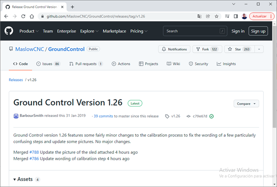
1. First, download and install Ground Control Software v1.26 from this oficial website. (Extract files to a whatever folder)
https://github.com/MaslowCNC/GroundControl/releases/tag/v1.26
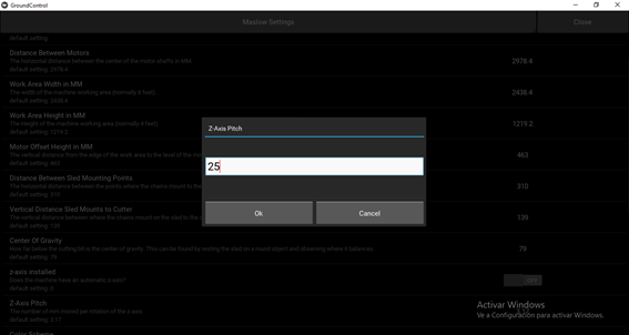
2. Launch application , go to Settings, on Maslow Settings change Z-Axis Pitch parameter to 25, because of Metal Maslow mechanism. Then Ok button to save configuration.

3. For calibrating process, goto Actions, Calibrate

4. A welcome text will appear, next press Begin button

5. Now, we select Triangular system, because system attaches the chains to a system of either linkages or bearings which let the ends of the chains rotate around the router bit as shown in the picture on the right.

6. Next, we need to enter a rough measurement for how far the motors are above the top of the work area. Measure from the center of the motor shaft to the top of the sheet of plywood. Millimeters units used.


7. Next, Orient each sprocket so that one tooth faces straight up in the 12:00 o'clock position, using the buttons to rotate left or right, the set zero

8. Next, we're going to use the chain to measure the distance between the motors.Hook the first link from the left chain over the top tooth on the left motor as shown in the picture below, the use the Extend button repeatedly to extend the chaing until it can reach the right motor.
Finally, use the Pull chain Tight and measure button to then pull the chain tight and take the measurement

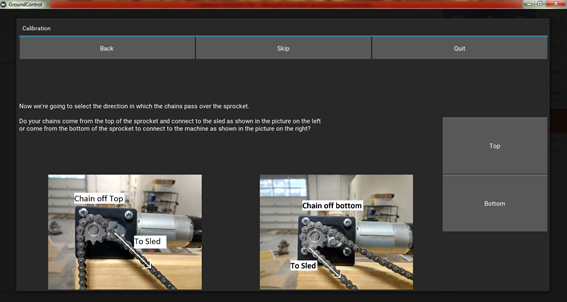
9. Now, we’re going to select the direction in which the chains pass over the sprocket. In this case Bottom selected
10. A report of measurements was generated in the software. Next, Looks Good button.

11. Remove chains and repeat step 7 to orient motor’s tooth.

12. Next, we need to enter a rough estimate for the rotation radius, this is the distance from the tip of the chain to the center of the router bit. Fort he ring the distance is 150mm.

13. This step will align the sled to the center. Set the chain like left picture below , then press Adjust Left Chain button. Repeat it on right chain. Once both chains are finished attach the sled, the press Next

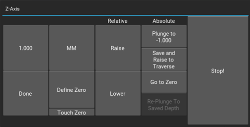
14. Next, it’s time to calibrate Z-axis, so we’re going to define the home position for the Z-axis. First, enable Automatic Z-Axis then press Adjust Z-axis button

15. The goal is to get the tip of the router flush with the work plate. Define the raise or lower value in millimeters, by pressing Raise to raise or Lower to lower. Then press Done button, Define Zero button
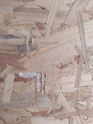
16. This is the last step. To refine these measurements we're going to cut a test shape. The test shape consists of five cuts.
a) Cuts 1 and 2, will be short vertical cuts in the upper left and right corners of the work area.
b) Cuts 3 and 4, will be short vertical cuts in the lower left and right corners of the work area.
c) Cut 5 will be a short horizontal cut attached to cut 2.
The start the Cut Test Pattern. After, take measuremtns and type on the boxes. Millimeters units used.

17.To get more precision, re-cut test pattern. Type the new measurements on the boxes. Repeat process until get best results. I mean Cuts 1 and 2 measurements so similar or equal to Cuts 3 and 4

Cut 1
Cut 2

Cut 3

Cut 4

Cut 5
Cut pattern test

Z-axis calibration
II. Ground Control Configuration
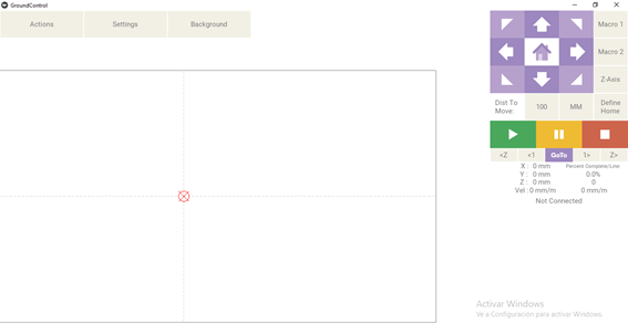
1. On the main screen of Ground Control we’ve some options to control the router.
On Left side we’ve PLAY button to start the cutting process, PAUSE button to pause the cutting process and STOP button. The HOME button to set the router initial position. The four arrows to move the router in all directions even diagonally movement. The step distance can be changed using mm or inches
2. Next, Go to Actions option, Ports, and select the available COM port to connect to the Maslow CNC. Then press Connect button

3. Next, Go to Actions option and press Open File button. Select a .NC file and open it


4. Now, we’re ready to start the cutting process
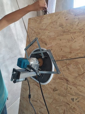
III. Cutting Process:
1. First, the checklist:
*check the 12V power supply connected and turned on,
*check the router is connected to 220V and turned on,
*check the router is HOME position, including Z-axis
*check the handles to the cutting material,
*check the cables are free.
2. Press PLAY button to start the cutting process
3. Video
Download Section
Download Ground Control configuration here.
Download some files for cutting: silla.nc gato.nc cuadrado.nc cuadrado2.nc
Problems and solutions
In the development of the project we found some problems that were solved:
1. The material of the structure is too hard in a dry environment, therefore it was placed in a more humid environment, which would allow us to easily drill it to assemble it.
2. In the first instance, thick wire was used to support the counterweights, however, we did not know that it was very unstable and damaged. So we replaced it with metallic wire, which allowed us a correct functioning of the counterweights.
3. Initially, the wiring was installed in an unordered manner, which made it difficult for us to move the head. It was solved by better ordering the cables and with protection.
4. Regarding the calibration issue, we realized that the final stage was not so precise, so we had to carry out the process several times, giving us better precision to make the cuts.
5. The software generates a configuration file that we were not aware of, since when using the software on another computer that information was lost. We fixed it by digging deeper into the software and capturing the groundcontrol.ini file which contains all the configuration and calibration information.
Future improvements
- In the design of the machine, the installation of wheels to transport the machine to different areas was not taken into account. However, they can be easily installed.
- In the next version a Raspberry Pi will be used to control the MASLOW CNC
- It is planned to do future tests with another material for the structure in such a way that it continues to be hard but less heavy. This will facilitate its transport considerably.