Output Devices
In this activity I used a Fabduino PCB Board with a servomotor SG-90 to control the angle of movement.
Servomotor SG-90
This analog micro servo will rotate up to 180 degrees (90 in each direction). You can expect it to operate the same as standard versions, but this micro servo is much smaller and can fit into tighter spaces. Its lightweight (9g) design will still output a high amount of power. This servo will work with any servo library, code, or compatible hardware.

Specifications
Product Name: Pro 9g mini servo(S version)
Manufacturers ID: TPSG90S
Size: 0.866”x0.48”x1.142”
Weight: 9g
Products Torque: 8.96lp/inch(4.8V) 1.6kg/cm
Reaction speed: 0.1sec / 60degree (4.8v)
Operating voltage: 3.0V-7.2V
Temperature: 0-55 degrees
Action Dead: 10us
Gear Media: Nylon
Mode: Analog
Pin Configuration
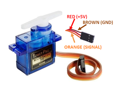
1. VCC: It has a power supply of 3.5V to 5.5V.
2. Ground: The module usually connects to the ground of a circuit.
3. Signal: Controlled by PWM.
Once the servo motor is connected, the Arduino Nano can send pulse signals to the servo motor to control its position. A servo motor is controlled by sending a series of pulses through the signal line. The width of the pulse is what determines the angular position of the servo, which can typically rotate up to 180 degrees, as it has physical limits. Generally pulses with 1ms duration correspond to 0 degrees position, 1.5ms duration to 90 degrees and 2ms to 180 degrees.

While the duration of the pulses required to control a servo motor is typically standardized, the minimum and maximum pulse durations may vary depending on the specific brand or model of the servo motor being used.
Fabduino
I used my Fabduino board to do this assignment, that can be found in Assignment 08 Electronics Design.
Previuosly designed in other assignments.
Components used
01 Fabduino PCB Board
01 Servomotor SG-90
01 External Power Supply
Jumpers
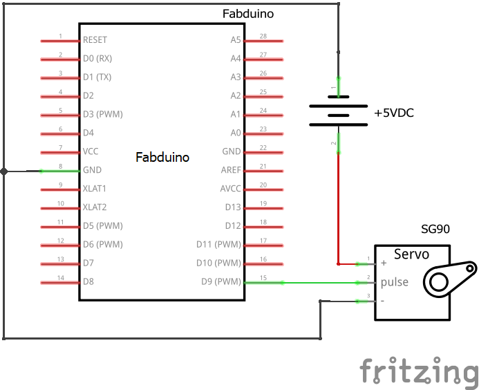
So, I made the next circuit to test the servo motor.
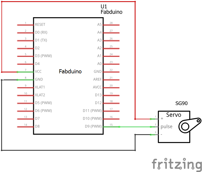
Schematic Circuit
I used PWM pin (pin D9) and VCC and GND.
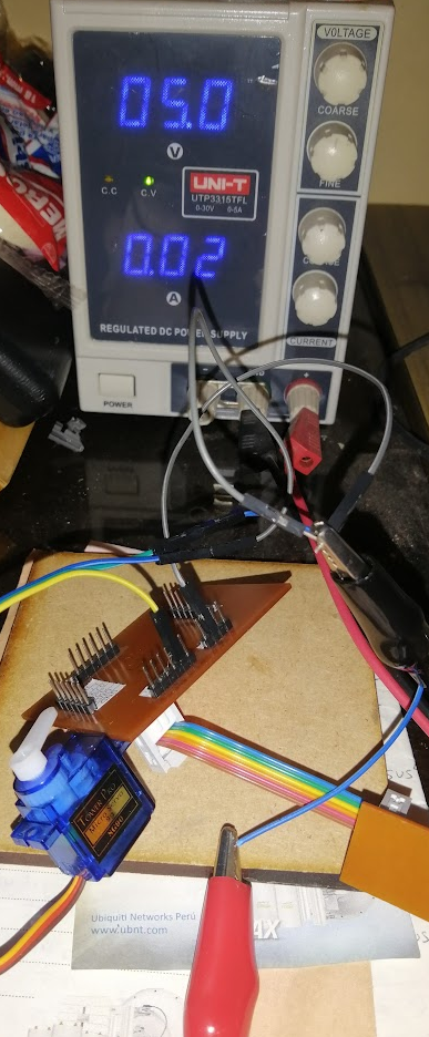
Next, I've tested with a external power supply
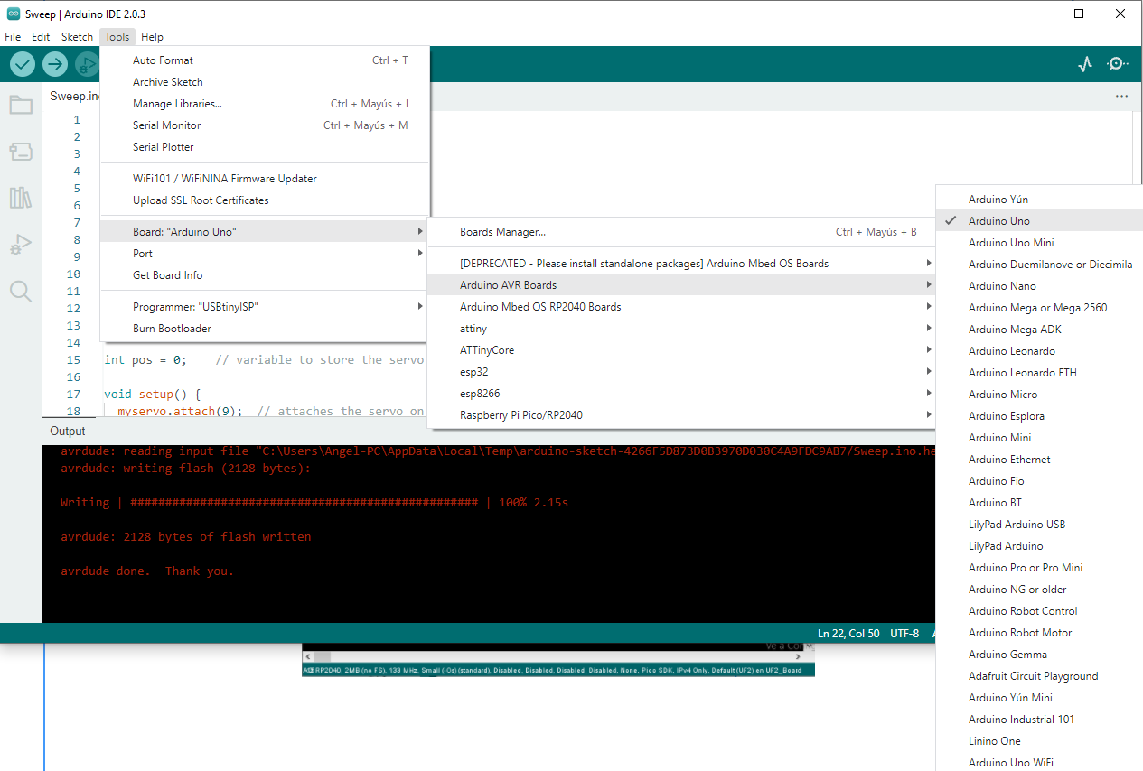
Programming the PCB Boards
In the programming IDE we must select the board Arduino UNO and program using FabISP
Test Code / Firmware
//I've used as reference the arduino code from git repository (for controlling a servo motor)
//https://github.com/arduino-libraries/Servo/blob/master/examples/Sweep/Sweep.ino
/* Sweep
by BARRAGAN
This example code is in the public domain.
modified 28 May 2015
by Michael C. Miller
modified 8 Nov 2013
by Scott Fitzgerald
http://arduino.cc/en/Tutorial/Sweep
*/
#include <Servo.h>
Servo myservo; // create servo object to control a servo
// twelve servo objects can be created on most boards
void setup() {
myservo.attach(9); // attaches the servo on D9 pin Fabduino to the servo object
}
void loop() {
int pos;
for (pos = 0; pos <= 180; pos += 1) { // goes from 0 degrees to 180 degrees
// in steps of 1 degree
myservo.write(pos); // tell servo to go to position in variable 'pos'
delay(15); // waits 15ms for the servo to reach the position
}
for (pos = 180; pos >= 0; pos -= 1) { // goes from 180 degrees to 0 degrees
myservo.write(pos); // tell servo to go to position in variable 'pos'
delay(15); // waits 15ms for the servo to reach the position
}
}
Testing
In this test I used a servomotor SG-90, angles from 0 to 180 degrees in a loop. The Servo.h library was used.
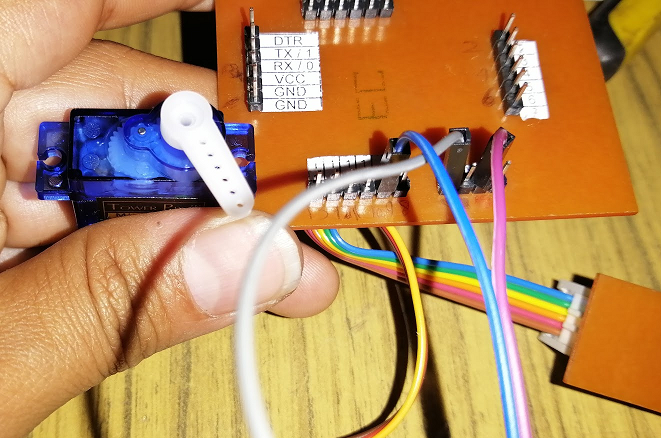
Servomotor connected at 0 degrees.
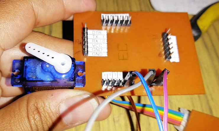
Servomotor connected at 180 degrees
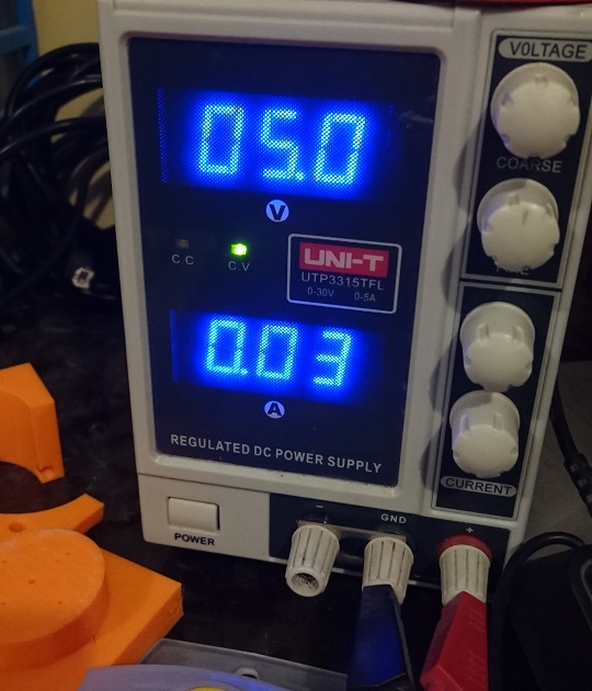
Testing with a external power supply to measure the DC current. The average value is 0.03A (30 mA) at 5V, I mean 150mWatt.