Electronics Design
Group assignment
In this assignment I've tested, measure and analize the operating voltage with a multimeter and oscilloscope. I used a 12VDC 1A switching power supply,
my FabDuino and a couple of cables.
My FabDuino has a DC jack to energize the circuit. First, I've measured the operating voltage.

Then, I used the oscilloscope to view the signal.
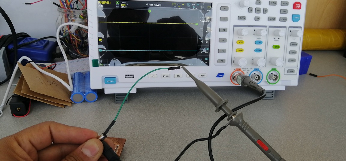
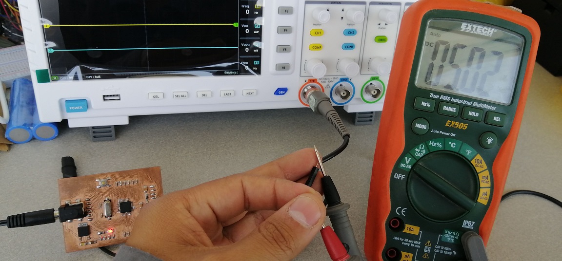
The Fabduino board uses a +5V regulator to energize the microcontroller (ATmega328p), so I used the multimeter to measure the operating value for the circuit.
So, I can see the value is 5.02 Volts on the multimeter.
Oscilloscopes have much faster measurement engines and much wider measurement bandwidths than digital multimeters, but they often don't achieve the accuracy and resolution of a multimeter. Oscilloscopes typically have a resolution similar to a digital multimeter of 3,5 to 4 digits.
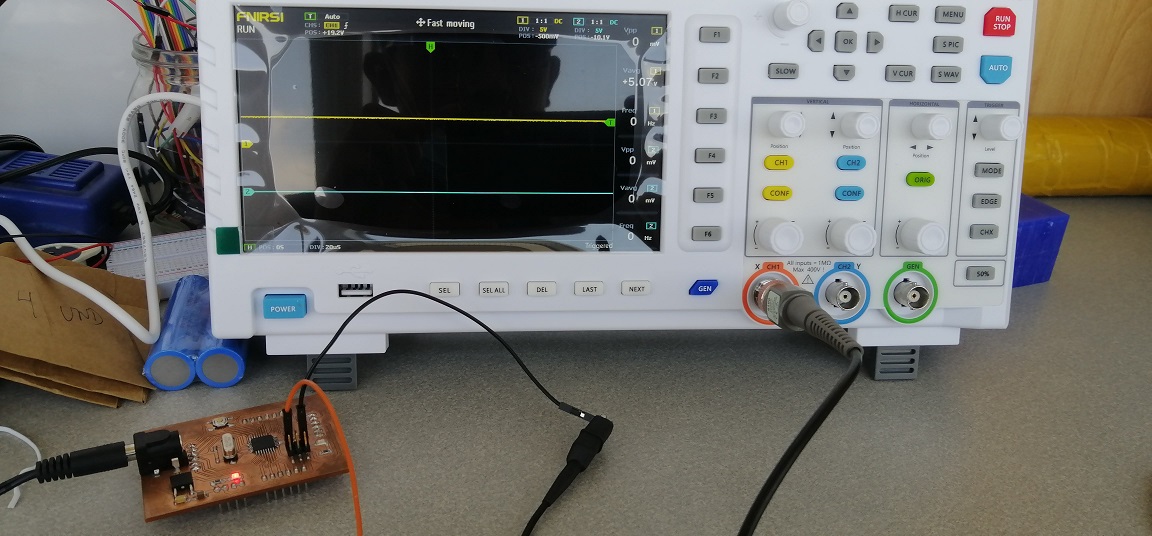
Now, I used the oscilloscope and checked the same value.

I used 5us DIV to view the signal.

I can see some data of the signal like Vmax is 5.17V, Vavg is 5.07V, where Vmax is the maximum voltage measured, vmin is the minimum voltage, vavg is the average voltage, and Vp is the peak voltage.
The noise of signal is very low, I'm using a switching power supply.
Individual assignment
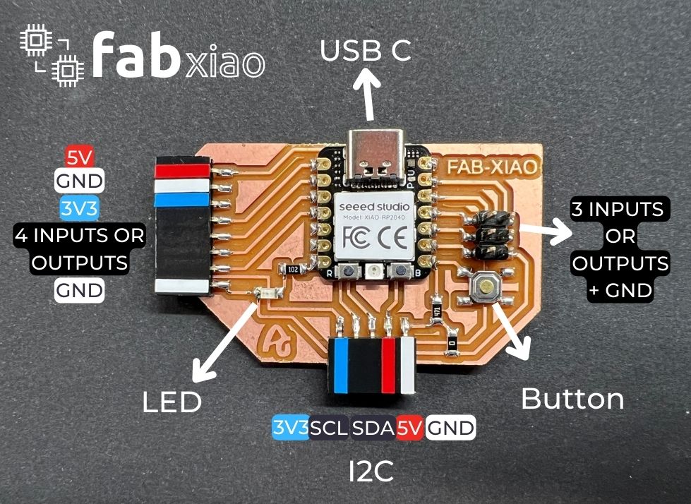
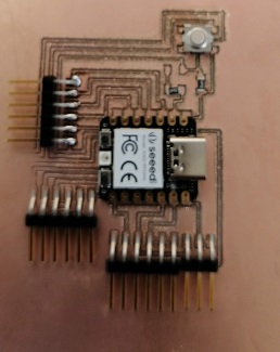
I made my own board based on Fab XIAO project, I mean, my board has another pinout and a UART port, in addition to the SPI and digital port.
The RGB led, the boot and reset button, are inside the XIAO itself.
Original Fab XIAO
Link: http://fabacademy.org/2020/labs/leon/students/adrian-torres/fabxiao.html
I added some features to make it more complete.
- A button on D0 digital pin
- A LED on D1 digital pin
- A Digital port on D2, D3, D4, D5 and D6
- A UART port on D6 TX and D7 RX.
- A SPI port on D8, D9 and D10.
- Some pins for GND, 3.3V and 5V

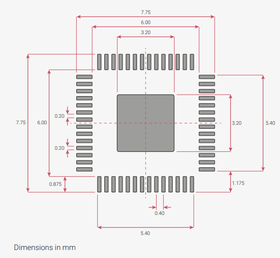
The controller used is an XIAO RP2040 QFN56, datasheet here.

RP2040 chip meaning
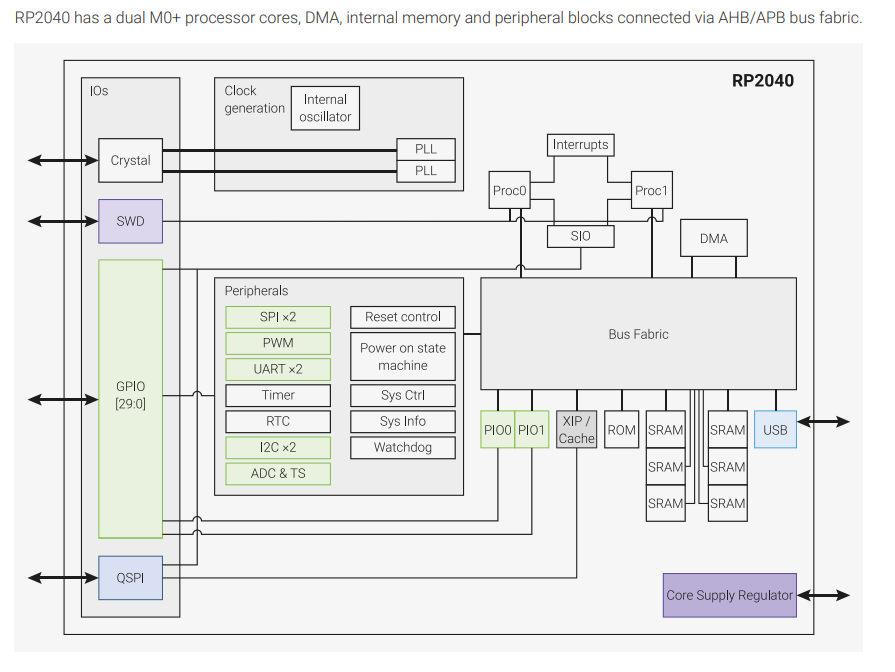
Overview RP2040 chip

Pin Description
- GPIOx General-purpose digital input and output. RP2040 can connect one of a number of internal peripherals to each GPIO, or control GPIOs directly from software.
- GPIOx/ADCy General-purpose digital input and output, with analogue-to-digital converter function. The RP2040 ADC has an analogue multiplexer which can select any one of these pins, and sample the voltage.
- QSPIx Interface to a SPI, Dual-SPI or Quad-SPI flash device, with execute-in-place support. These pins can also be used as software-controlled GPIOs, if they are not required for flash access.
- USB_DM and USB_DP USB controller, supporting Full Speed device and Full/Low Speed host. A 27Ω series termination resistor is required on each pin, but bus pullups and pulldowns are provided internally.
- XIN and XOUT Connect a crystal to RP2040’s crystal oscillator. XIN can also be used as a single-ended CMOS clock input, with XOUT disconnected. The USB bootloader requires a 12 MHz crystal or 12 MHz clock input.
- RUN Global asynchronous reset pin. Reset when driven low, run when driven high. If no external reset is required, this pin can be tied directly to IOVDD.
- SWCLK and SWDIO Access to the internal Serial Wire Debug multi-drop bus. Provides debug access to both processors, and can be used to download code.
- TESTEN Factory test mode pin. Tie to GND.
- GND Single external ground connection, bonded to a number of internal ground pads on the RP2040 die
- IOVDD Power supply for digital GPIOs, nominal voltage 1.8 V to 3.3 V
- USB_IOVDD Power supply for internal USB Full Speed PHY, nominal voltage 3.3 V
- ADC_IOVDDD Power supply for analogue-to-digital converter, nominal voltage 3.3 V
- VREG_IOVDD Power input for the internal core voltage regulator, nominal voltage 1.8 V to 3.3 V
- VREG_VOUT Power output for the internal core voltage regulator, nominal voltage 1.1 V, 100 mA max current
- DVDD Digital core power supply, nominal voltage 1.1 V. Can be connected to VREG_VOUT, or to some other board-level power supply.
A 4990 code of SMD resistor (499Ω) was chosen for low bright at turning on the board and the test pin D1. Datasheet 1206 led
R = (Vs - VLED) / iLED,
where:
Vs is the source voltage, measured in volts (V),
VLED is the voltage drop across the LED, measured in volts (V),
iLED is the current through the LED, measured in Amperes (Amps/A), and
R is the resistance, measured in Ohms (Ω).
R = (3.3V - 2V) / 5mA
R = 1.3 / 0.010
R = 260 Ω
A pull-down button was added too, for general purposes. The 4990 resistor value is chosen for low current flow to the microcontroller.
DRC
In the Design Rules I used the default, I mean, single layer, 8mil (0.2032mm) for wires, pads and vias.
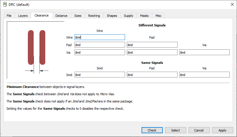
So, We'll see the minimum dimension between pins is 0.20 mm. The value of 8mil (0.2032mm) was good.
I selected 'check' option and show no errors.
ERC
The tracks were manually routed. Manually it seems more personalized to me, I can better optimize the spaces and distances between components.
I check the ERC electrical rules, no errors on design, I mean no overlapping traces, holes.
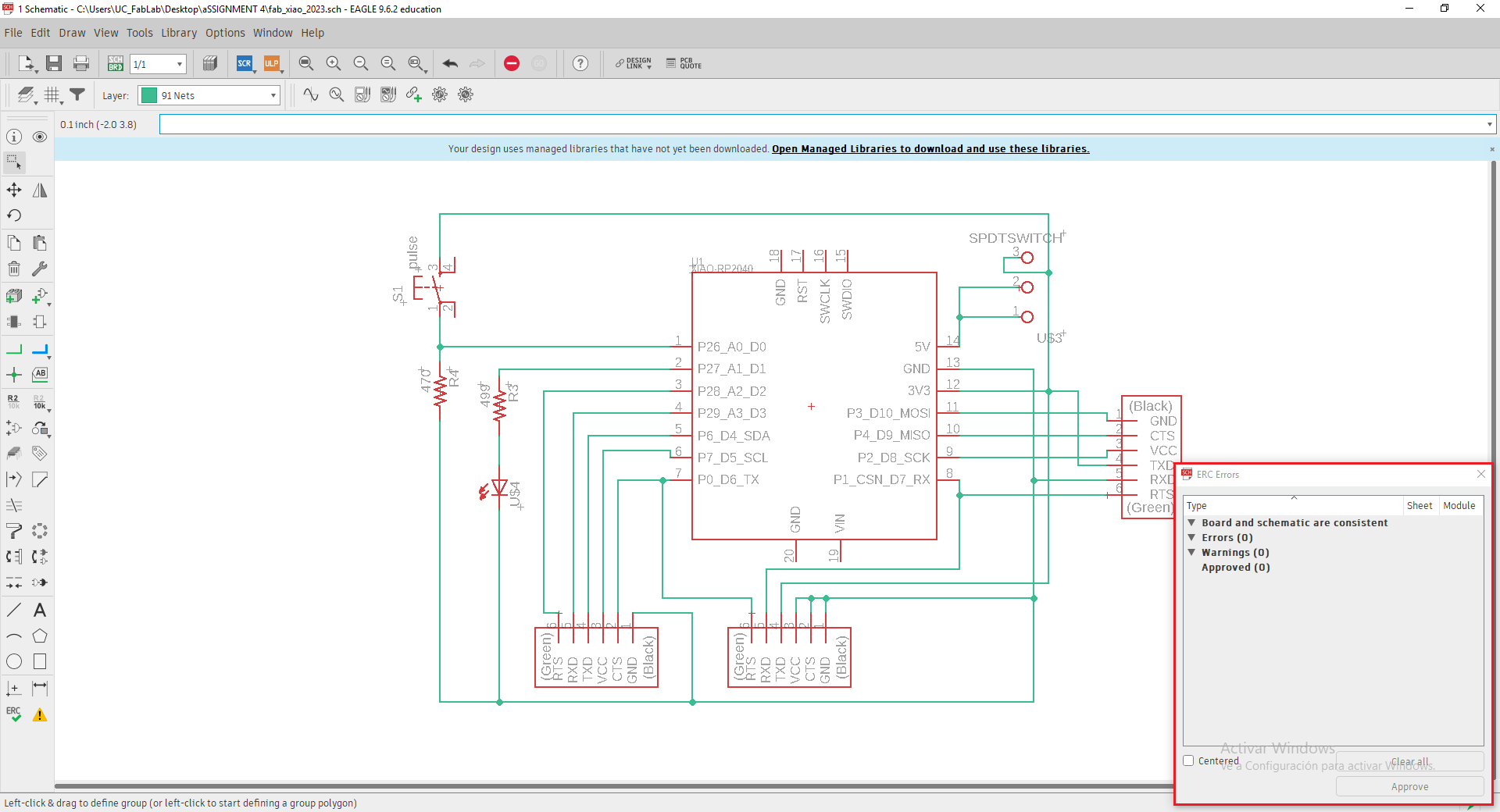

I tried Autorouter tool in other software like Proteus, but I feel more comfortable on Eagle.
Milling Files
To generate the milling files I selected the CAM PROCESSOR option on the PCB Board edition.

Then, I need to configure some settings, set a filename: xiao2023.gbr (gerber extension). On the right side I checked the layers to mill. In this case I selected TOP, PADS and VIAS. Then go to process job button.
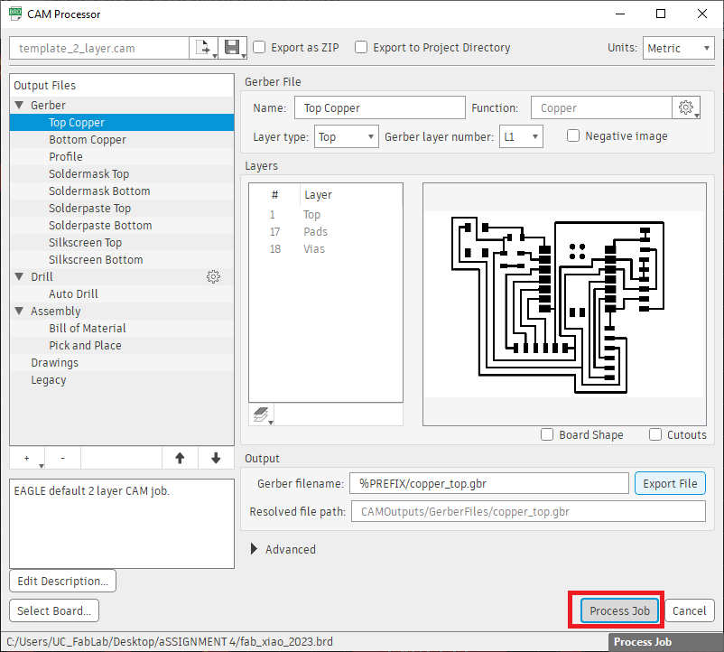
Then I selected Process Job to generate the GERBER files.
I follow thid guide to this process. Link
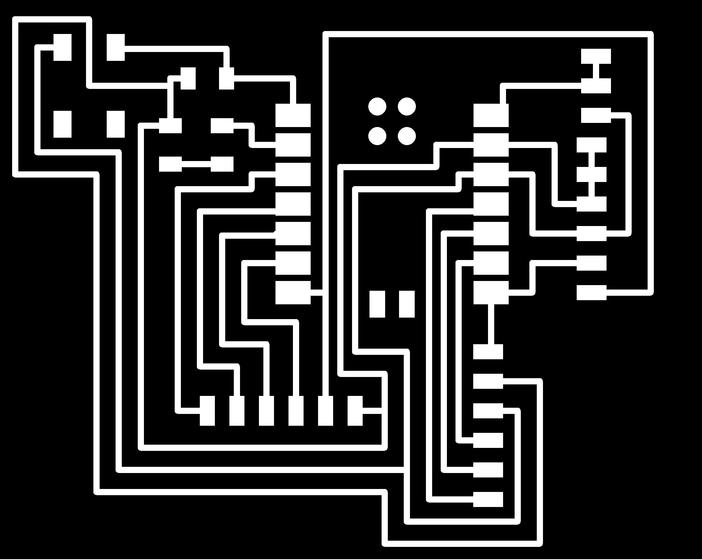
I consider it appropriate to place the image of the PCB board in black and white format in order to use it in some other milling program.

Note:
During this week I was testing other software like KiCAD. I realized that is easy to use, but I prefer Eagle because I have a lot of years using it.
I actually used kicad in the first instance, but I had some difficulties, so I used Eagle, the software that I mastered the most.
Files
Share schematics and board files (sch and brd) can be downloaded here.
My XIAO PCB Board design (PNG) here
References
For operating the miniCNC machine I used manual and guides, links below:
MACH4 CNC Controller Operations Guide
Eagle, GERBER generating files guide
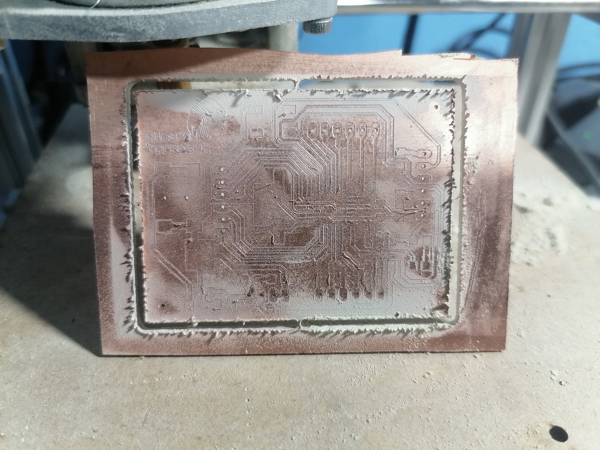
Milling process

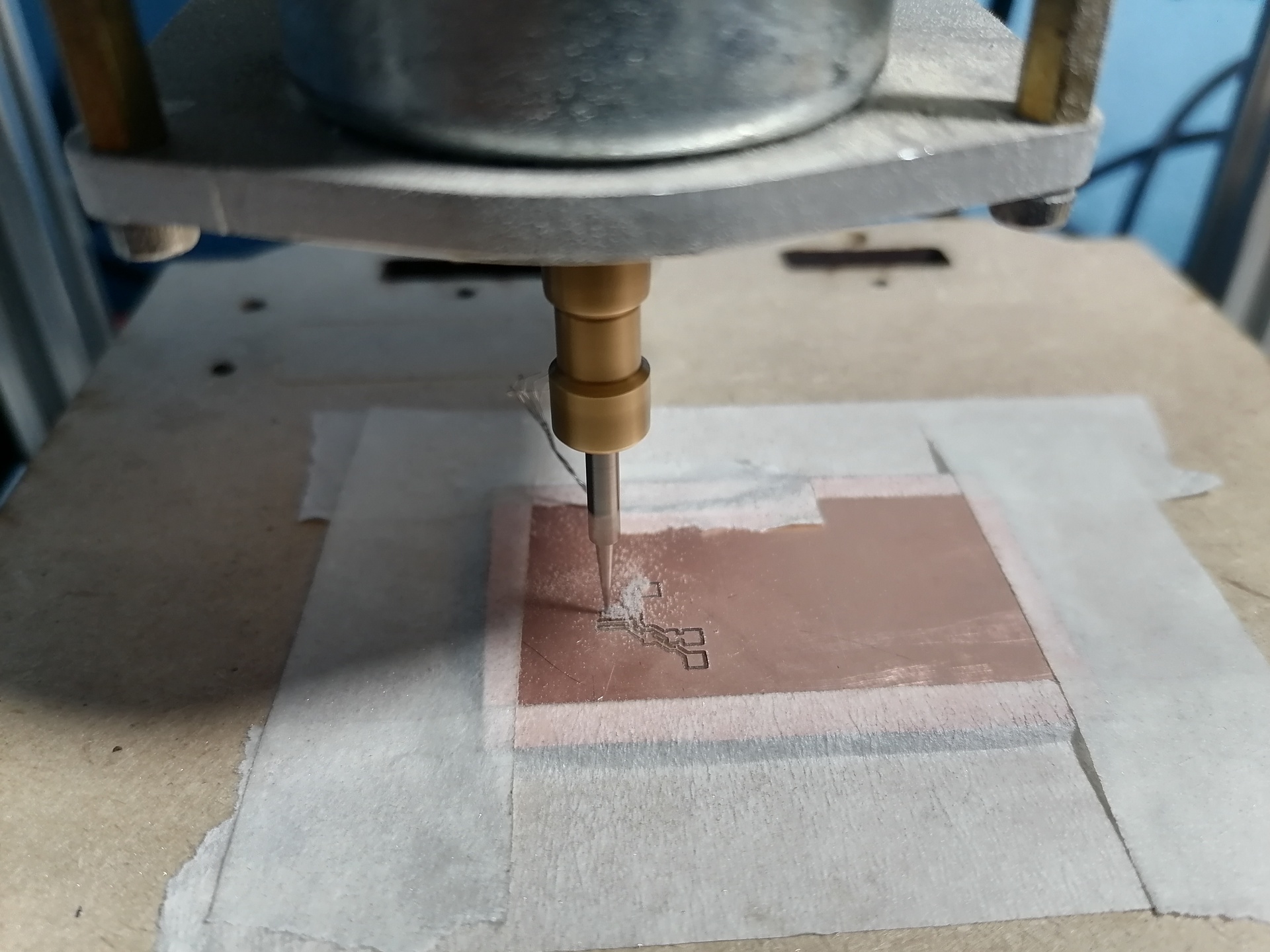
First attempt at PCB milling

I used four fasteners on the ends of the plate to improve grip

Some tracks didn't turn out as expected
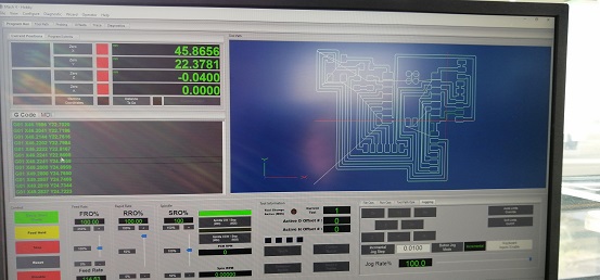
Milling Path on MACH4
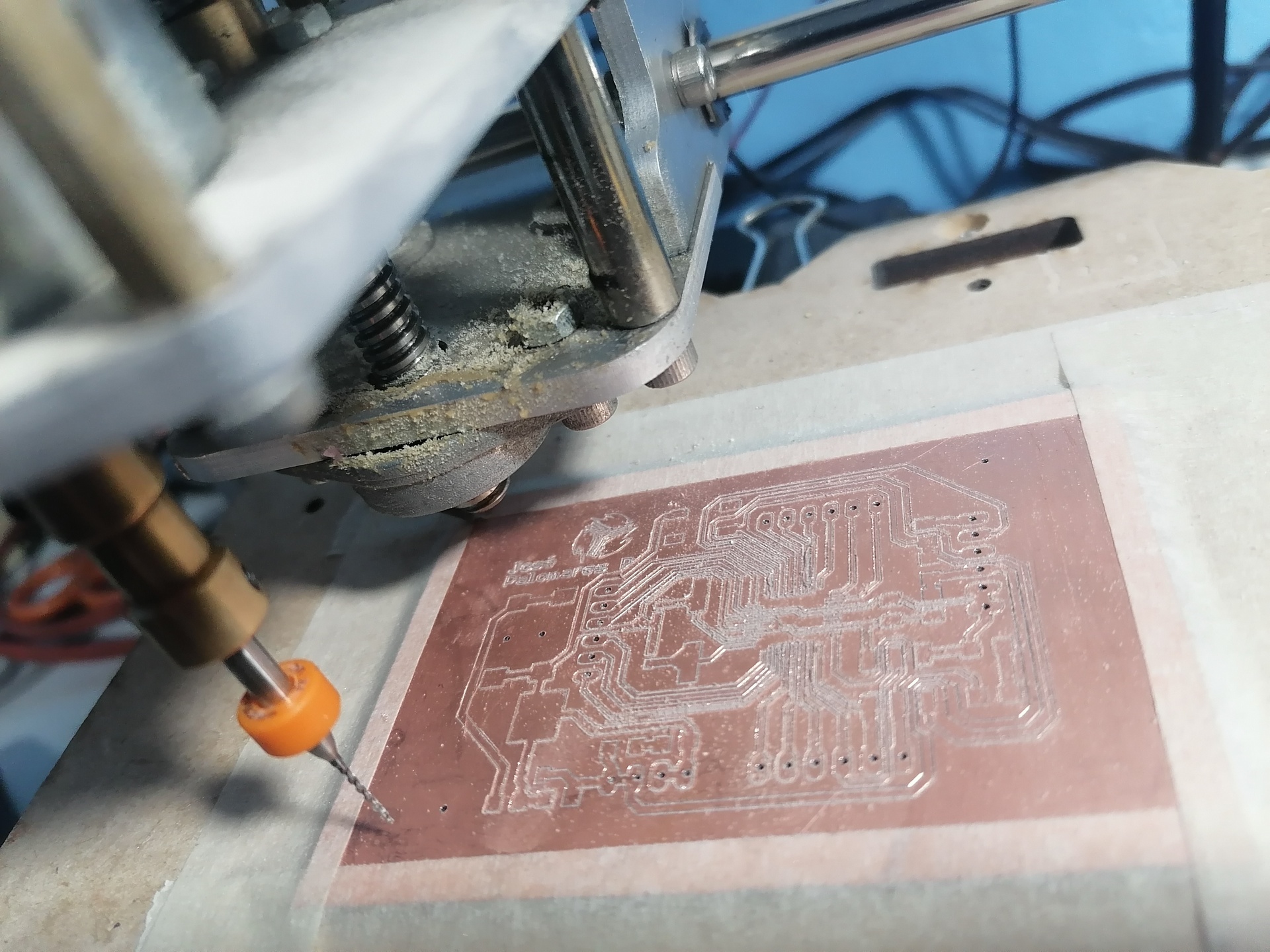
Milling Fabduino
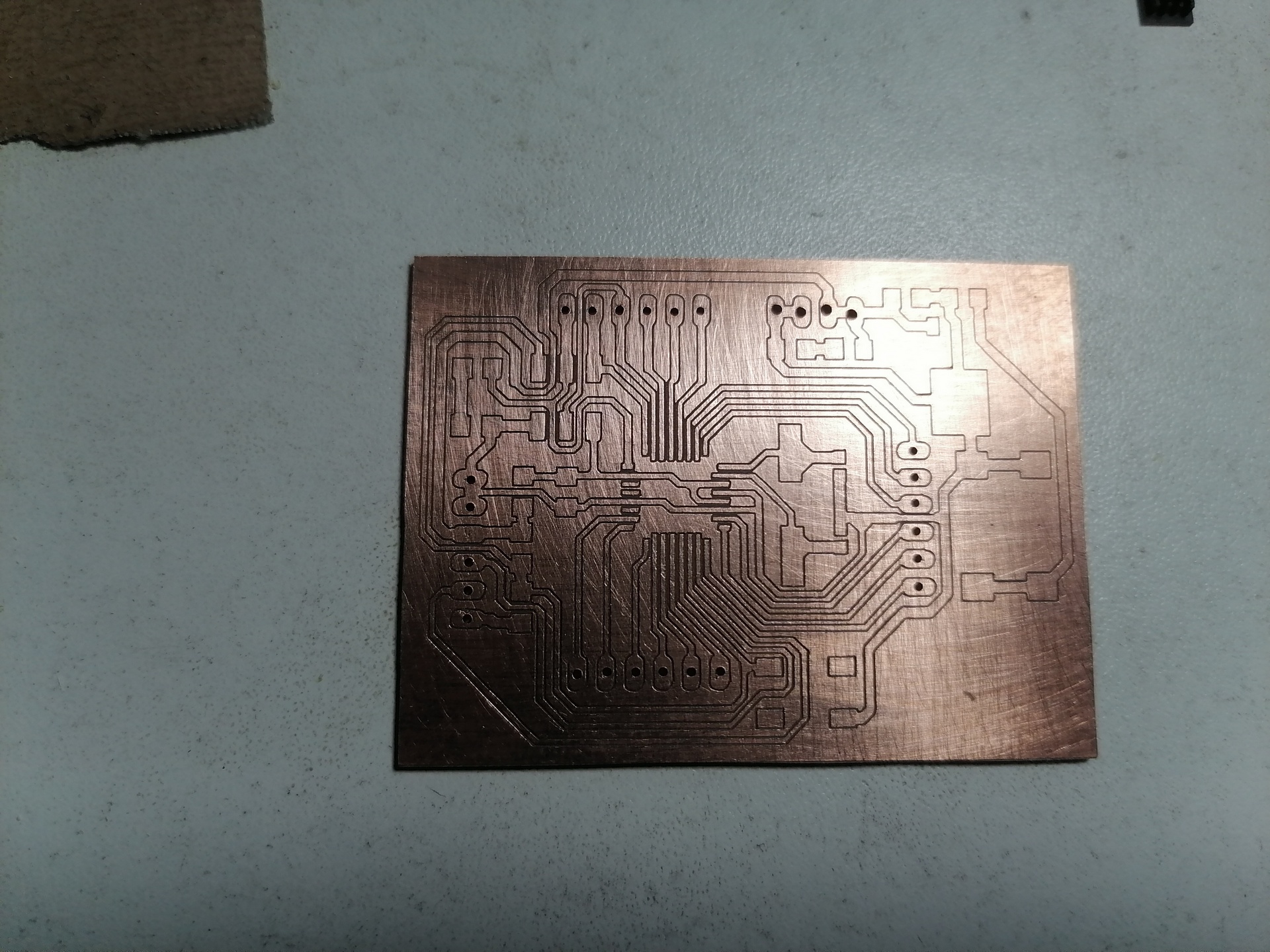
Previously I had some inaccuracies when milling so I decided to use another mini CNC. Where I got better precision on the plate.
MiniCNC details:
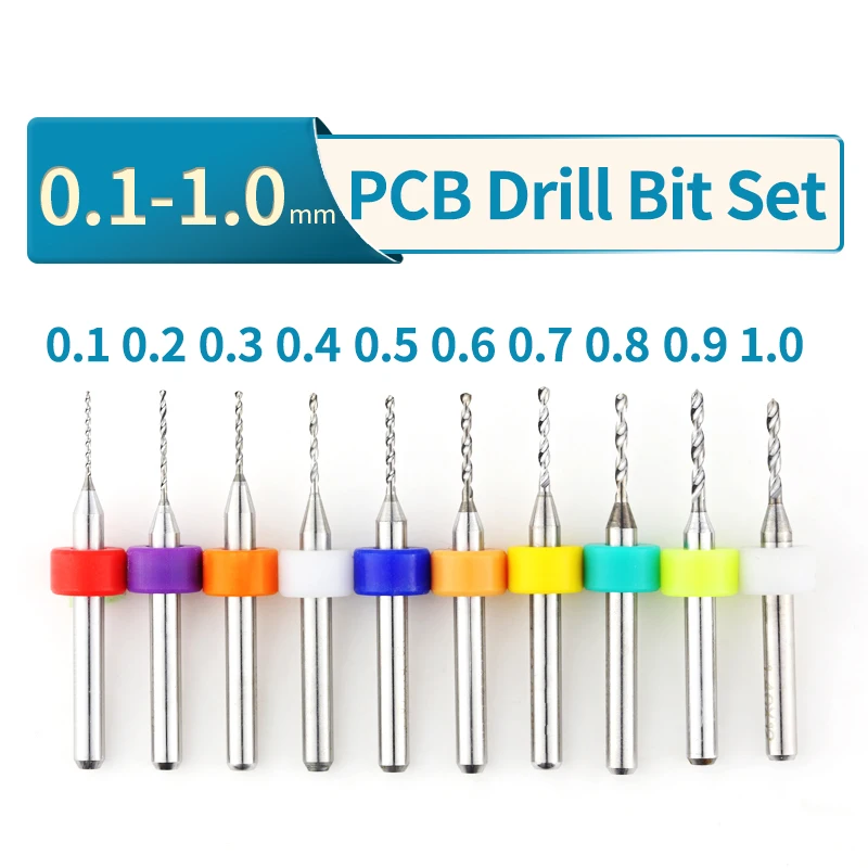
The milling tool I've used is a v-bit type, 30 degreees, 0.1mm (for paths)

And I've used a drill bit to cut the border. (1.0mm diameter)
To hold the plate on the platform, use masking tape on all edges of the plate, so that it remains static and as flat as possible to avoid any errors.
Once the tracks were milled I proceeded to cut the edge.
In the cutting configuration, leave 1.5mm spaces (gap) at the beginning and end to prevent the plate from moving in the final moments of the cut.
By applying a little cleaning with isopropyl alcohol you can see the perfect cut of the PCB board.
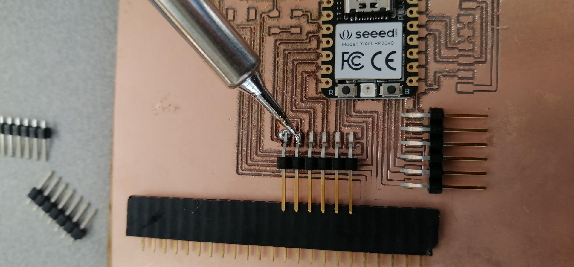
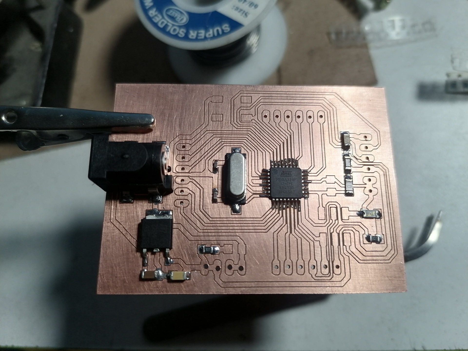
The next step was to solder the components to the board, being very careful not to overheat them.
Component list:
01 ATMEGA328P microcontroller SMD
01 10K ohm resistor
01 Button (reset)
02 499 ohm resistor
02 Led
02 Capacitor 0.1 uF
02 18pF Capacitor
01 pinhead (ICSP)
01 pinhead (6 pin) (port C)
01 pinhead (6 pin) (port D)
01 pinhead (6 pin) (port B)
01 pinhead (4 pin) power
01 Pinhead (6 pin) (UART port)
02 Capacitor 10uF
01 Jack 12V
01 16 MHZ crystal
01 0 ohm resistor
01 7805DT voltage regulator (5V)


So, I made some labels to identify the Fabduino pins .
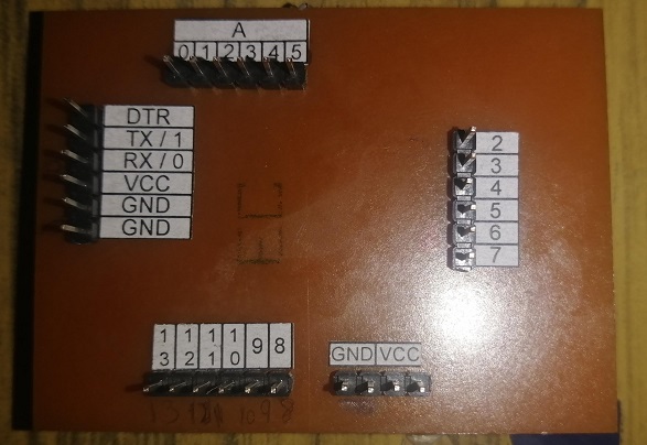
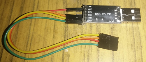
To make the serial communication of my PCB board with the computer I used a USB to TTL adapter. This is connected to the Rx and Tx pins of the microcontroller.

Testing board:
I programmed a code for serial communication using the UART port of my Fabduino board, in such a way, specifically when writing a word, it returns as an echo.
Code:
char inByte; // incoming serial byte
void setup() {
// put your setup code here, to run once:
Serial.begin(9600); // serial communication baud rate
}
void loop() {
// while loop begins here, continous loop:
if (Serial.available()) { // check for incoming data --> if available
inByte = Serial.read(); // store incoming data
Serial.print(inByte); // echo back the data
}
}
Connection:
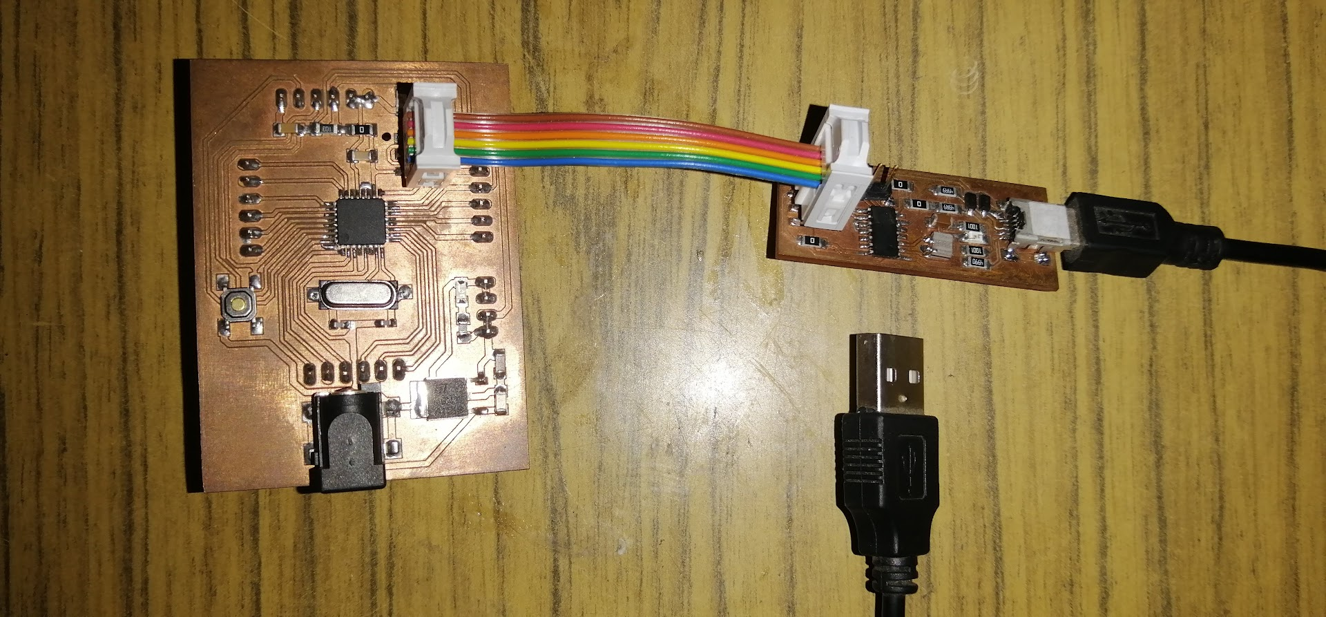
First, I connected the ICSP cable to ICSP port of Fabduino and FabISP. Then, I connected the USB port to your computer.
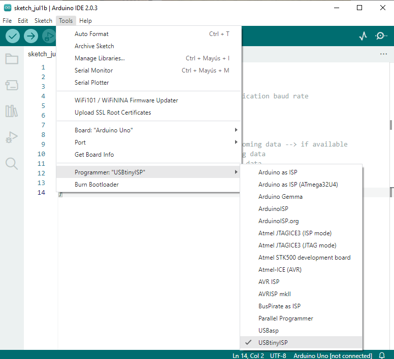
Next, I've selected the programmer USBTinyISP. (for FabISP)
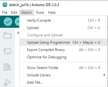
Next, I've compiled the code and select the option Sketch menu, Upload using programmer.
Then, I've disconnected the USB cable and connected the USB to TTL cable (Rx and Tx pins). Next, I selected the port for serial communication and I opened the Serial Monitor in Arduino IDE.
