Computer Controlled Machining
CNC What is it?
Computer numerical control (CNC) is a manufacturing method that automates the control, movement and precision of machine tools through the use of preprogrammed computer software, which is embedded inside the tools.
CNC is commonly used in manufacturing for machining metal and plastic parts. Mills, lathes, routers, drills, grinders, water jets and lasers are common cutting tools whose operations can also be automated with CNC. It can also be used to control nonmachine tools, such as welding, electronic assembly and filament-winding machines.
Materials and equipment
- CNC machine YINGHE YH-1214
- Link: https://es.made-in-china.com/co_yinghemachine/product_CNC-Yh-1224-Engraver-Machine-Yinghe-brand-_uoiosnuosu.html
- 18mm MDF
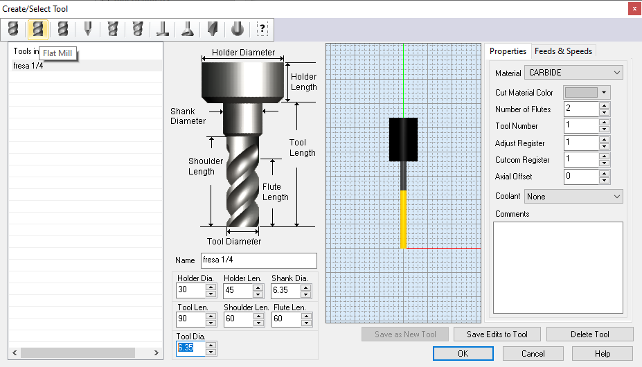
- 1/4'' mill (6.35mm)
- Safety equipment
First of all, we must bear in mind the identification of the CNC equipment
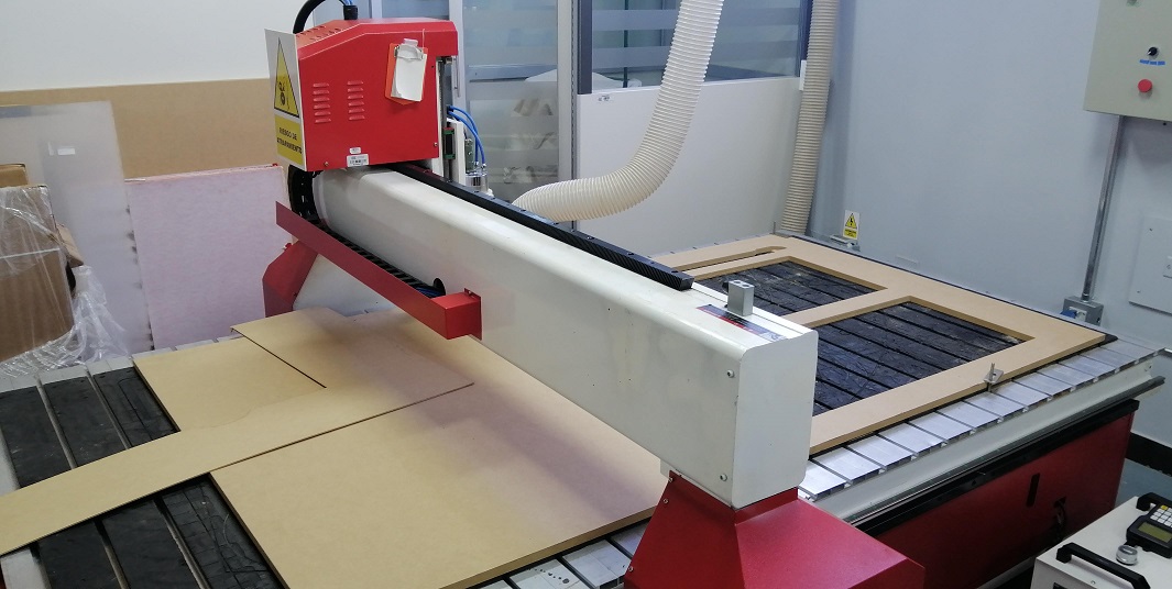
YINGHE YH-1224 CNC machine: The machine in charge of carrying out the roughing and cutting of MDF for our project. Workarea: 122 x 244 cms.
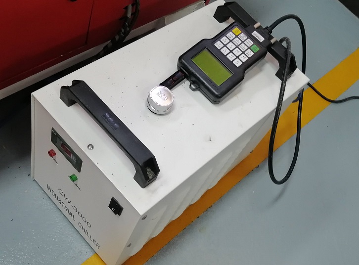
Chiller: The equipment that has the function of cooling the spindle that rotates at high revolutions. It should always be kept at room temperature.
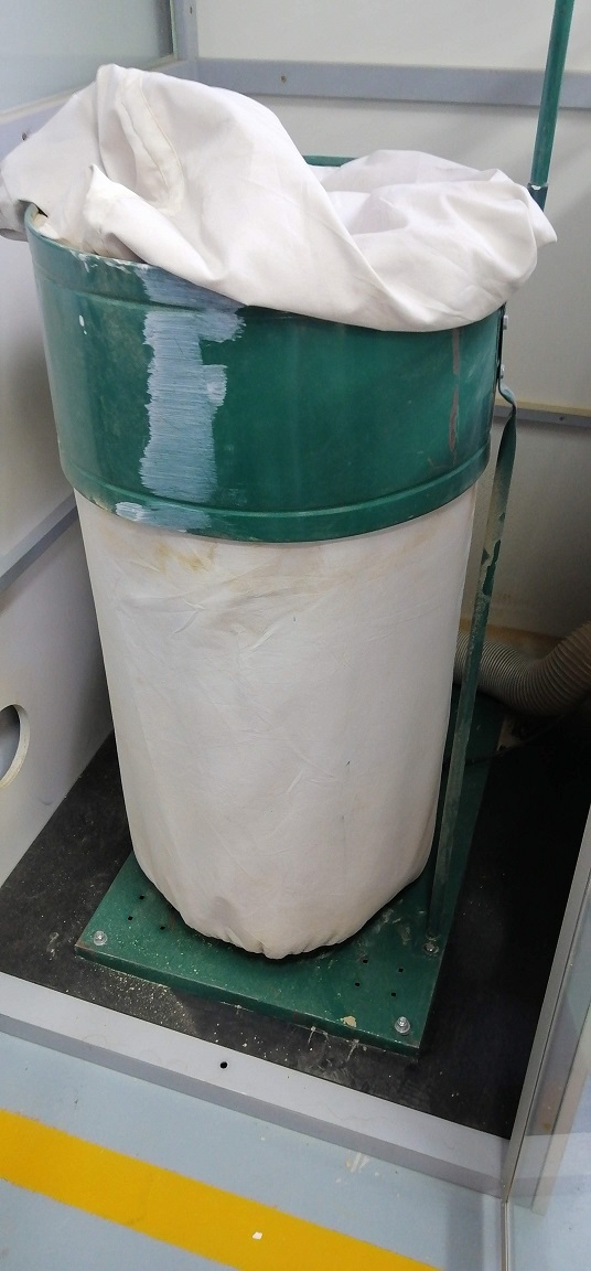
Dust extractor: This equipment has the function of extracting the dust and chips generated by the CNC milling machine. From time to time you have to do the respective cleaning.
Security zones are also very important.
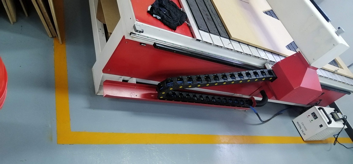
The CNC milling machine has an area delimited with a yellow tape. The marked area must be respected for the safety of the operator.
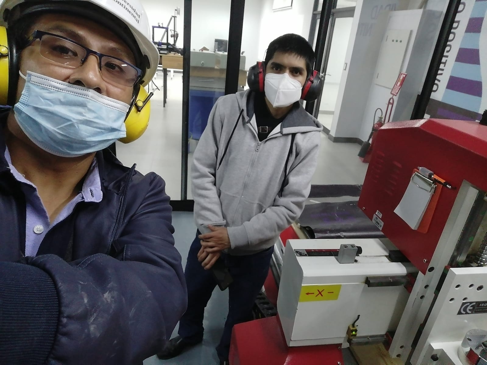
Finally the Personal Protection Equipment (PPE) to work safely on this machine.
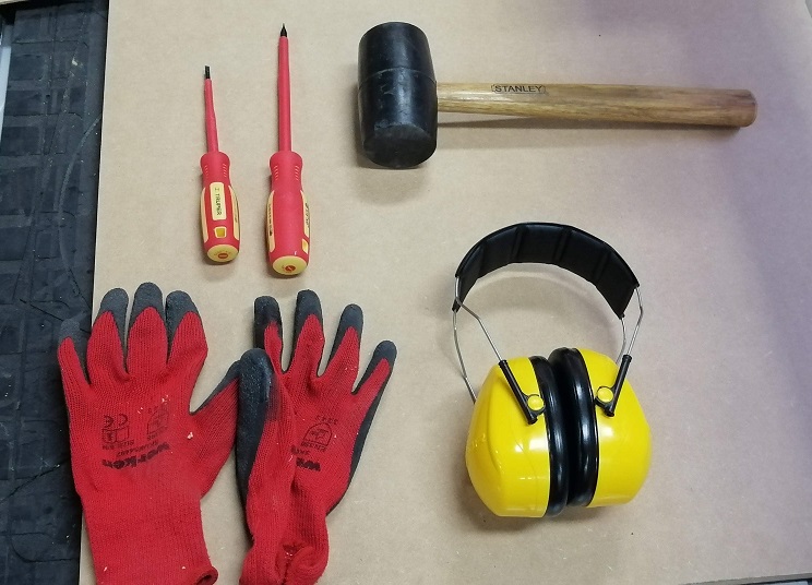
In this case we need the mandatory use of ear plugs to mitigate the noise generated by the CNC machine and dust extractor. The use of gloves to handle MDF sheets and fasteners is very important to take care of our hands. The use of minor tools is also necessary to extract some pieces of the platform.
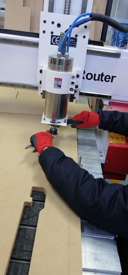
Finally we installed the milling cutter in the head to get our machine ready.
Support Material:
On the subject of fixing the material to the machine platform we can mention some options such as with screws, vacuum bed, or some pressure fasteners.
Our CNC machine has a slotted platform and rubber cloths, for this reason we do not use screws to fix the material. Another option would have been to opt for a vacuum bed to avoid placing any elements such as screws. However, the noise that the motor for the vacuum bed would generate added to the noise of the other motors of the machine and virtua extractor would exceed the permitted noise levels. Taking into account that we are on the 7th floor of the university, it would affect the other adjoining classrooms too much.
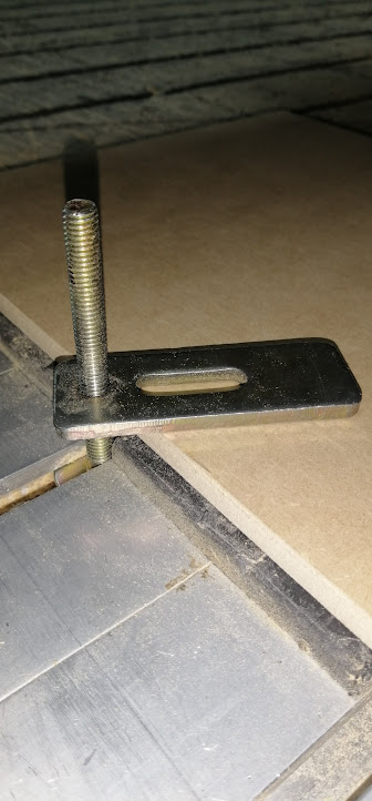
We place the fastener in the slot of the platform in such a way that it coincides with one of the edges of the material
Next, we rotate the fastener clockwise until there is the necessary pressure so that the material remains fixed and does not move.
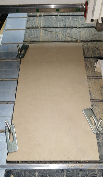
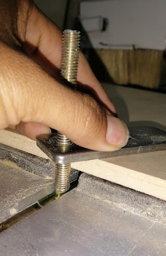
To work correctly, it will be enough to place 3 or 4 fasteners on the edges of the material.
With the material correctly adhered to the platform, we are ready to start the milling work!
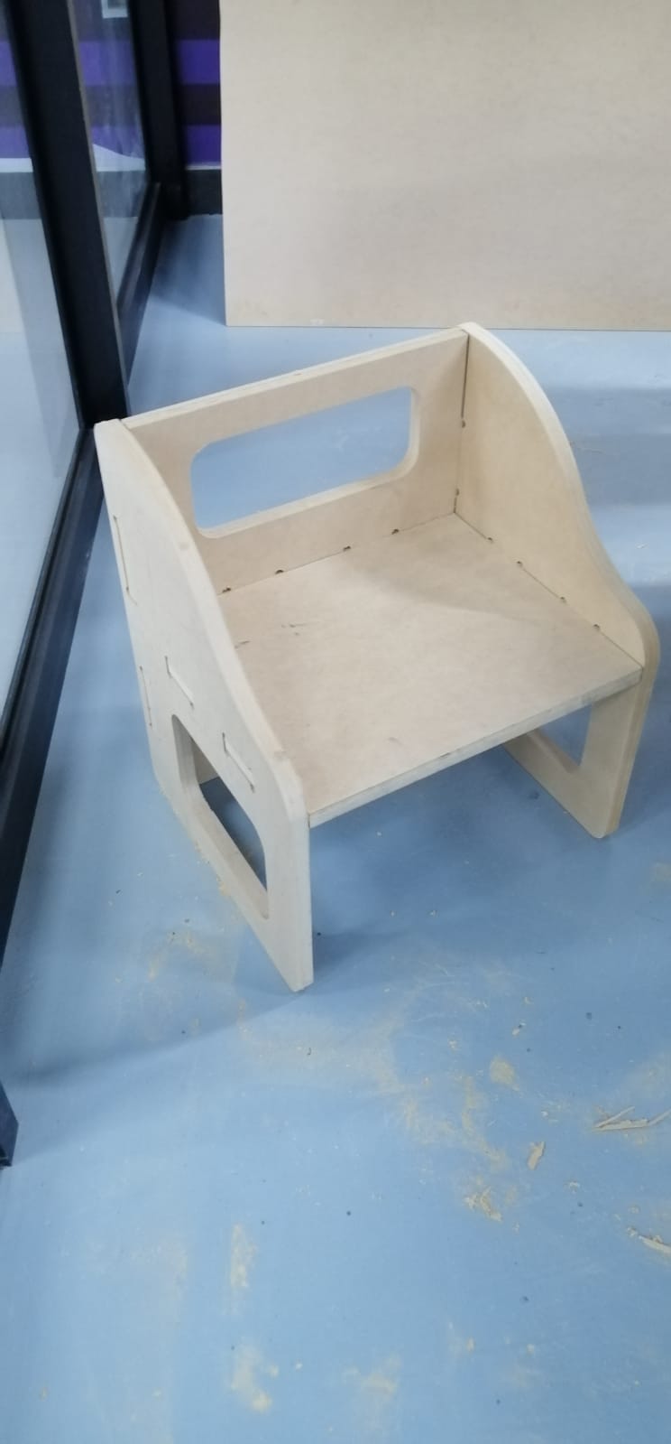
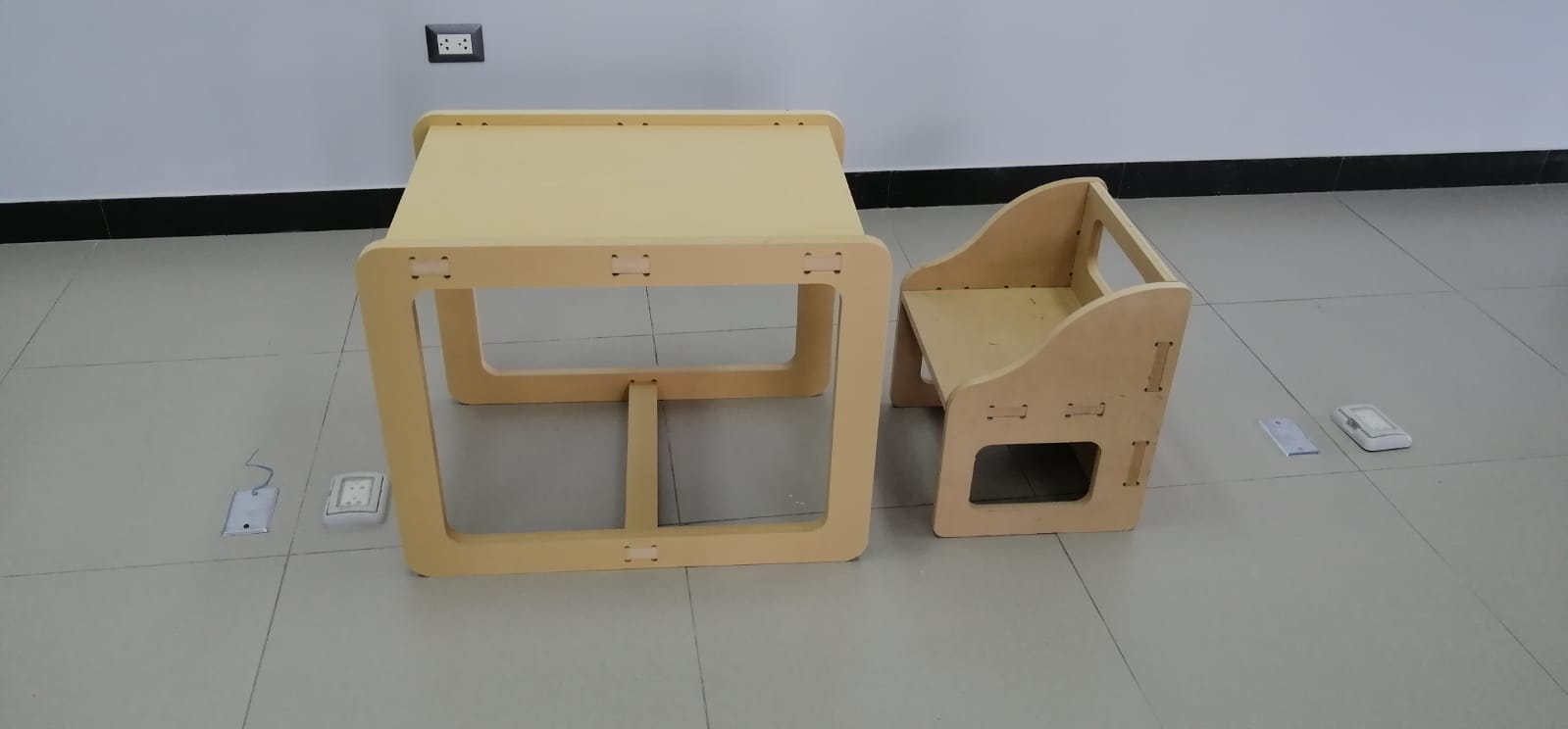
My Design
In this activity I decided to design a Montessori table and chair for kids.My goal is inspired in the image below.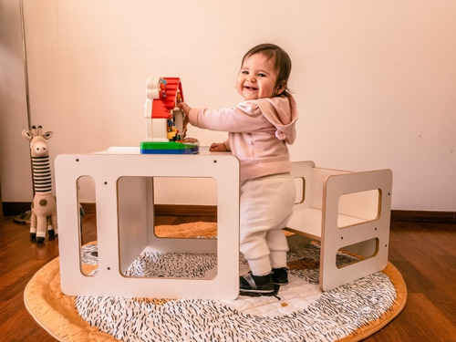
Design Process
STEP 1:
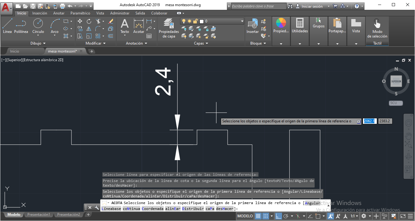
Determine the measurements of the table. Using AutoCAD software, the table was drawn. Width 5 cm for joints.

STEP 2:
A 2.4mm depth of MDF material was used for this design, so the height of the joint will be 2.4mm
STEP 3:
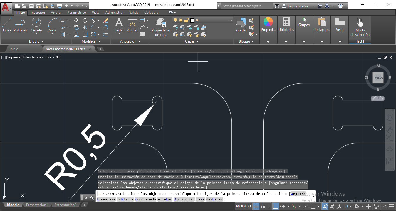
As well as we kwow, the borders will be circular beacause of the cutter, so , for best results we need to make additional circles on corners, like image below. We use 0.5mm of circular radius.
STEP 4:
In the tests we realized to consider a tolerance of 0.05 cm (0.5 mm) in both sides.

STEP 4:
Completing the design of the table.

STEP 5:
Now, the design was exported in DXF format.
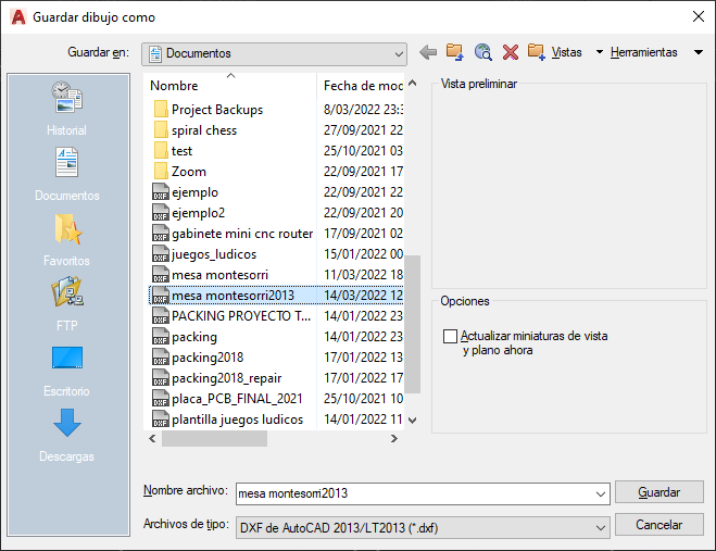
STEP 6:
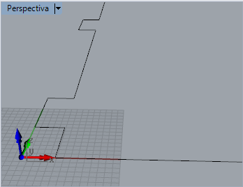
Next, the DXF exported file was imported on Rhinoceros 5 software.
STEP 7:
We can see the design in all views (Top, front, right, perspective)
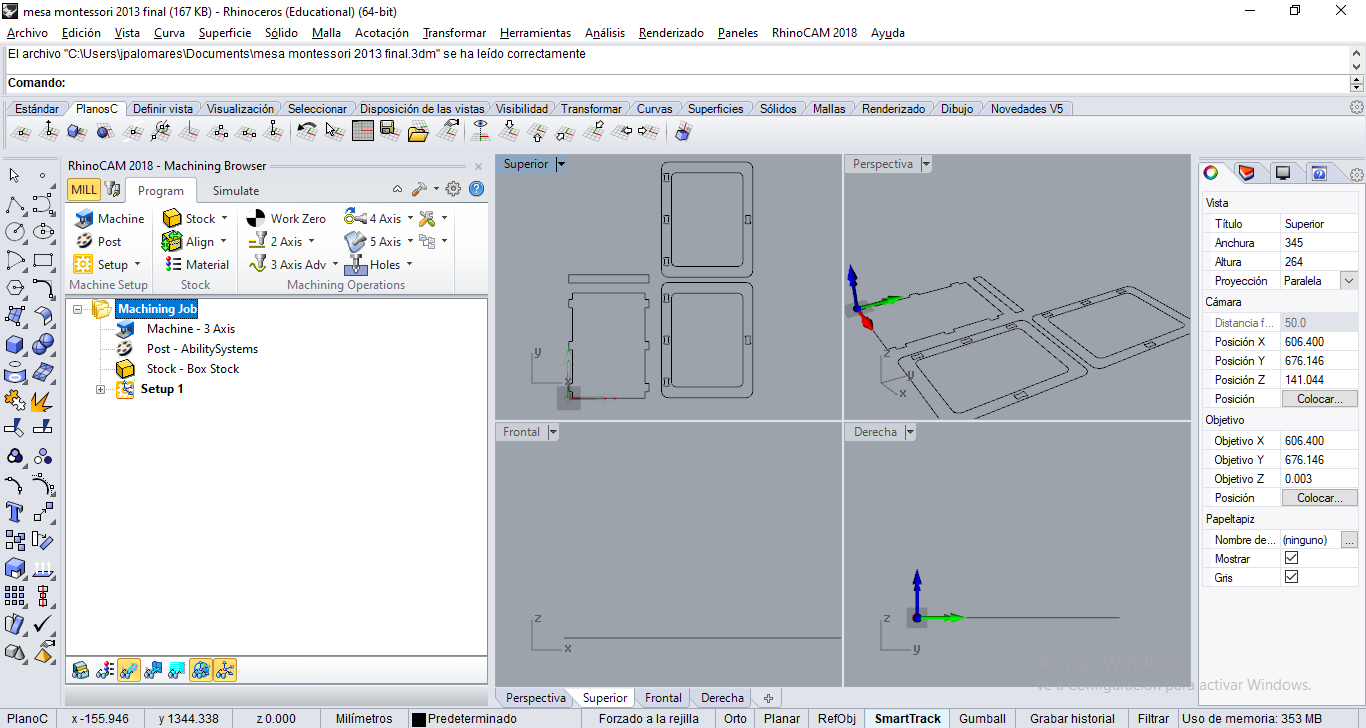
STEP 8:
Activate RhinoCAM 2018, MILL.
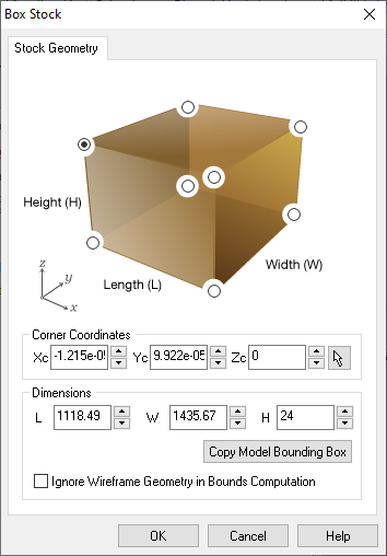
STEP 9:
We'll see some options for MILL. Select Stock Box. Copy Model Bounding Box, Height (H), and set 24 mm.
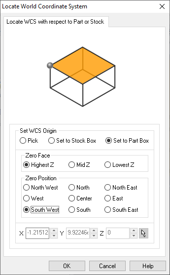
STEP 10:
Select Align, Set World C.S. option. Next, select Set to part box, Highest Z, South West.
STEP 11:
Next, select Work Zero option. Select Set to Stock Box, Highest Z, South West.

STEP 12:
Those settings are set to align x,y,z in zero.
STEP 13:
Next, the milling settings. Select 2-axis dropdown list and choose Profilling option.
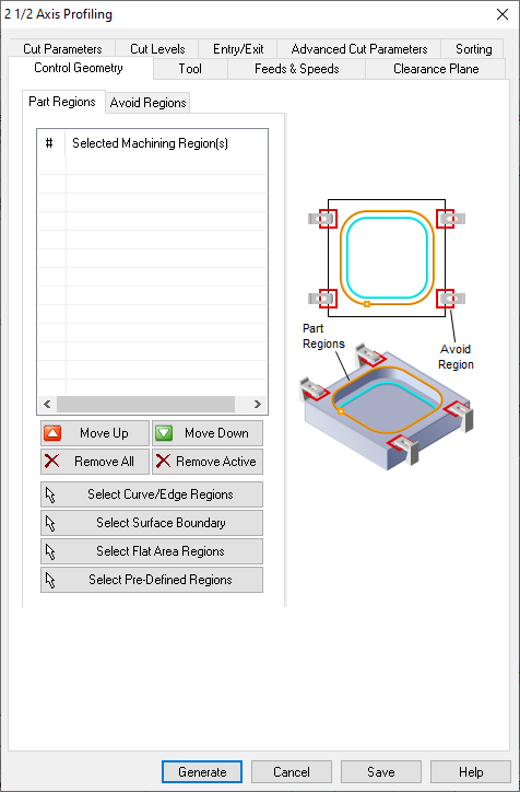
STEP 14:
Select curves or edges, first for inside elements.
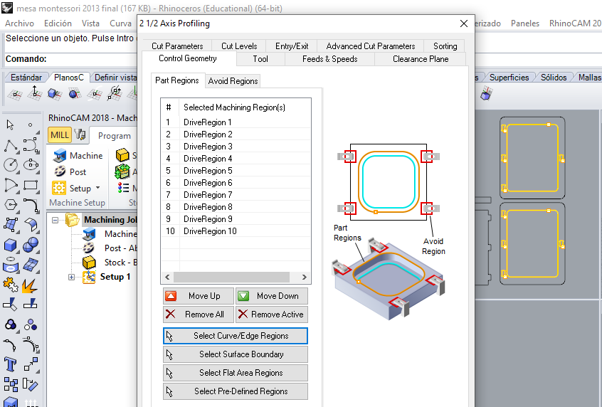
STEP 15:
Now configure the Profiling Parameters, Tool option, Select Flat Mill and set 6.35 mm on tool diameter (1/4 inch), next put a name for new tool.
Milling types:
In the laboratory we have some cutters for the CNC milling process. Below I show what we have.
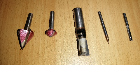
Milling cutters for profiling or engraving. Straight milling cutters and cutting milling cutters.
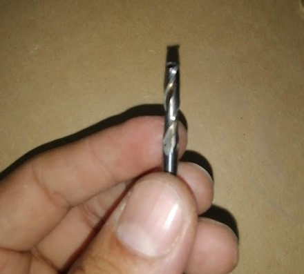
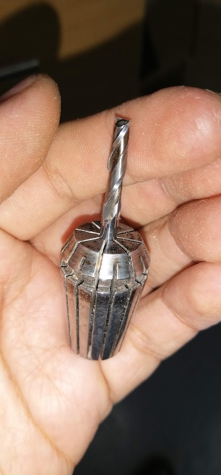
The following cutting milling cutter is the most used in our Fab Lab, since it allows us to make cuts with a good finish, and it is precisely the one we use to do this task.
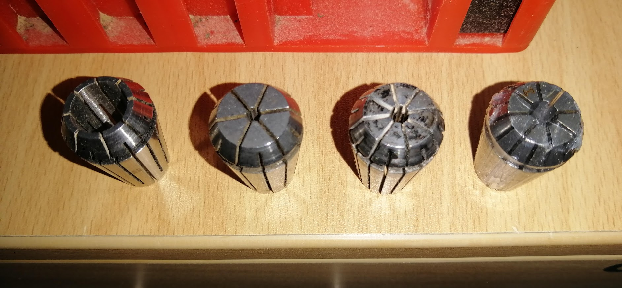
The milling cutters require an element called a collet chuck, which is where the milling cutter will be adjusted and then placed on the CNC milling machine.
As you can see in the image, they come in different sizes or diameters.
We place the milling tool through the hole and press inward to make it fit. It is very important to choose the correct collet chuck so that it fits well.
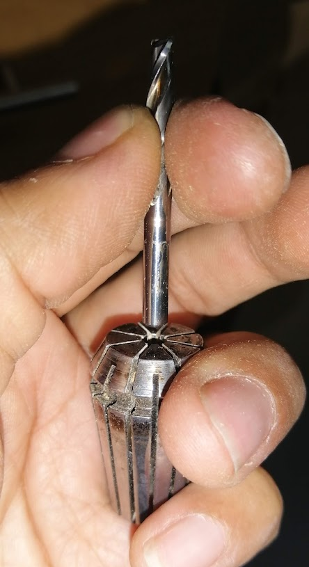
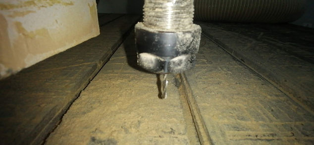
Finally we place the collet chuck and the milling cutter on the CNC milling machine and adjust it with the wrenches so that it is ready to start working.
STEP 16:
On Entry/exit parameters, set None in Entry Motions and None in Exit Motions.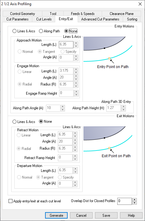
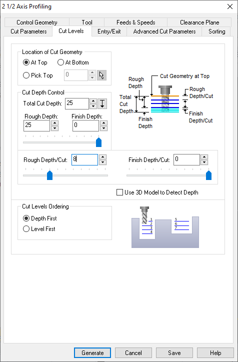
STEP 17:
On Cut Levels, Set total depth 25 mm, (1 mm additional tolerance). Set Depth Cut to 8. This means 3 passes of 8 mm and last 1mm.
STEP 18:
On Cut Parameters, check Use outside/inside for closed curves box. Now select Inside. Then select Generate button.

In Feeds and Speeds menu, I can set the parameters of the feed rates. The most critic for me is Cut (Cf) and Transfer (Tf). The units are in mm/min.

Here I will describe a little about feeds and speeds in the RHINO CAM settings.
Spindle Parameters:
Speed: By default, RPM speed of CNC 24000 RPM
Cut (Cf): Cut speed, 2000 mm/min, in DSP Controller. (Work Speed)
Transfer (Tf): Transfer speed 2000 mm/min, in DSP controller (Fast Speed)
Plunge (Pf): Z move, 0.2 scale (Fall down)
STEP 19:
Repeat the process with outside curves/edges . Use the same cutting tool settings, on Cut parameters change to Outside. Then select Generate button.

STEP 20:
Next, Put the inside options first, outside after.

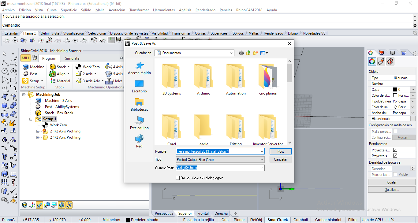
STEP 21:
Finally, Select Setup1, right click, select Post. Type a name, check .nc extension (G-code). The copy on usb drive.
Cutting Process
We assuming the MDF board is correctly adjusted on the platform of CNC machine. A 1/4 inch diameter cutter ready to cut.
STEP 1:
Put USB stick on DSP.

STEP 2:
Move axis X+ X- Y+ Y- Z+ Z- to calibrate the axis x,y,z origins using the DSP, next save position with XY-0, Z-0 buttons.

STEP 3:
Next, push RUN/PAUSE and select the .NC file we generated on Rhinoceros 5 software. Then push green button OK to start the cutting process.
As mentioned previously, in the SETWORKPARAM screen (work parameters), we can configure the speeds:
WorkSpd is cutting speed (CUT),
FastSpd is travel speed,
SpdScale is speed scale.
As you can see, it is controlled manually before making the cut, however there is a way to configure the DSP command so that it takes the values that we configured in our CAM software, for example RhinoCAM.
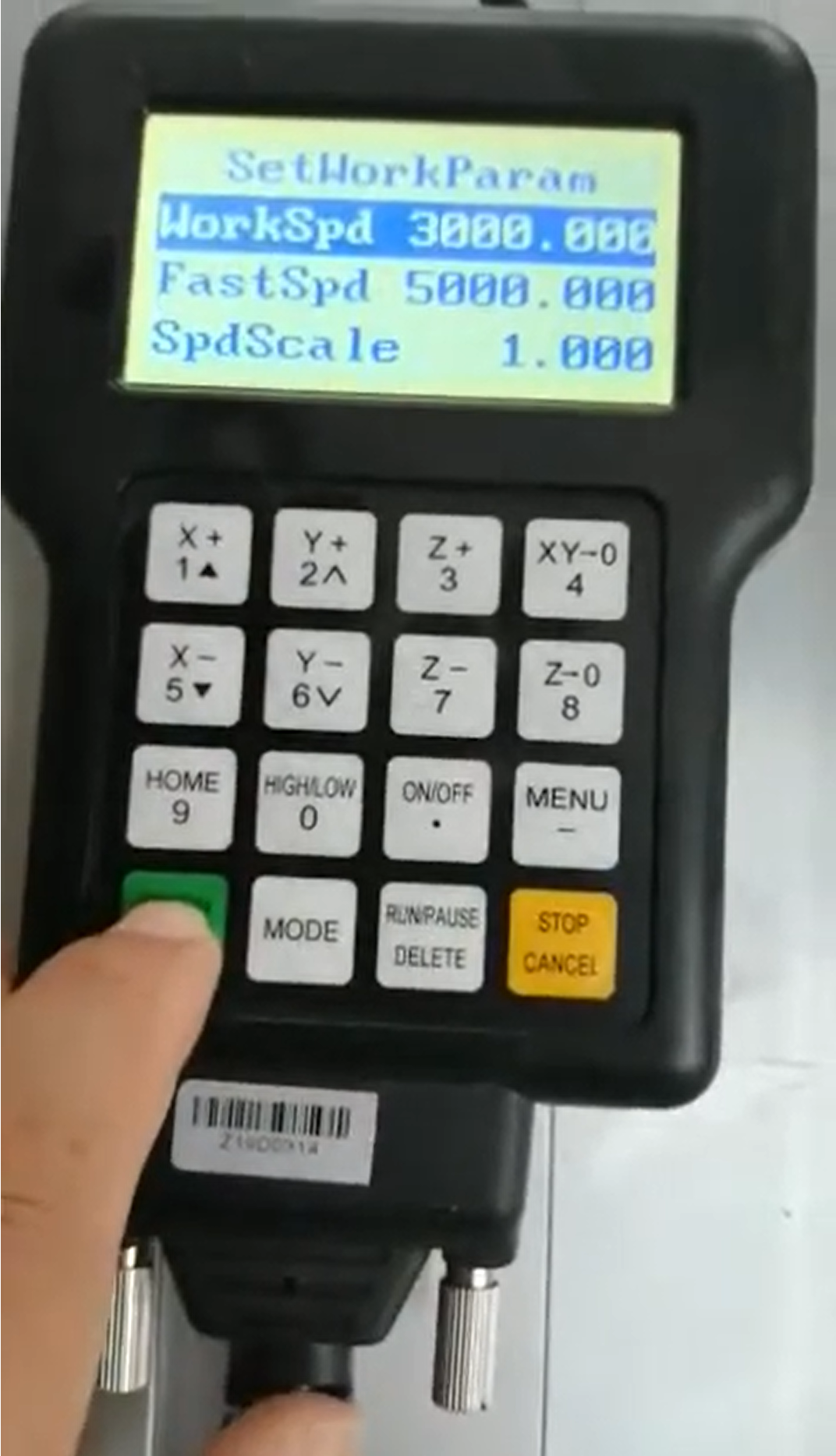
In this case, to perform this task, we set a value of 3000 mm/min, or 50 mm/sec, in WorkSpd and 5000 mm/min in FastSpd. Where there was no problem, since the machine normally supports those speeds.
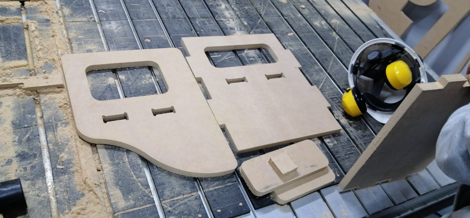
STEP 4:
Some photos of the process.


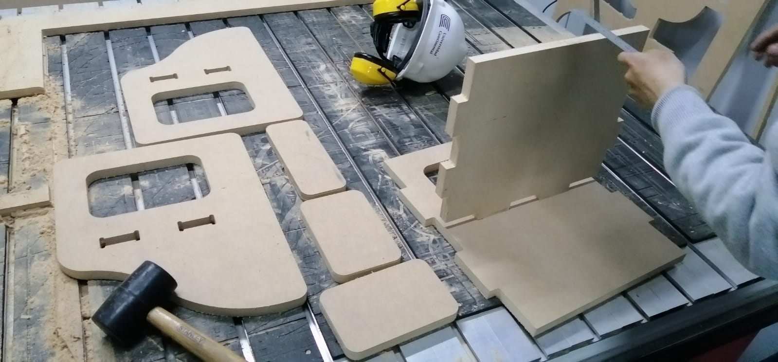
STEP 5:
We did the similar steps, but now for the Montessori chair.
Download
Project files and plans are available here
Takeaways Assignment
- I had to be very careful on this type of machine, since it uses rotating tools at high speed. Use the corresponding PPE.
- The lace technique helped me a lot to make a piece of furniture, however, the milling tool, being cylindrical, does not leave the cuts straight, therefore the dog bone technique must be performed, so that it can fit perfectly.
- It would be very useful to use a vacuum bed, since placing adjusters loses working space.