Embedded Programming
I will show information about the two computer architectures :
The von Neumann architecture — also known as the von Neumann model or Princeton architecture — is a computer architecture based on a 1945 description by John von Neumann, and by others, in the First Draft of a Report on the EDVAC.
The document describes a design architecture for an electronic digital computer with these components:
- A processing unit with both an arithmetic logic unit and processor registers
- A control unit that includes an instruction register and a program counter
- Memory that stores data and instructions
- External mass storage
- Input and output mechanisms
The Harvard architecture is a computer architecture with separate storage and signal pathways for instructions and data. It contrasts with the von Neumann architecture, where program instructions and data share the same memory and pathways.
The term originated from the Harvard Mark I relay-based computer, which stored instructions on punched tape (24 bits wide) and data in electro-mechanical counters. These early machines had data storage entirely contained within the central processing unit, and provided no access to the instruction storage as data. Programs needed to be loaded by an operator; the processor could not initialize itself.
In summary the main difference between the two is access to data memory and program memory. So:
- Von Neuman architecture has a single bus that is used to obtain instructions and transfer data.
- Harvard architecture has a separate memory space for instructions and data, physically separates signals and code from storage and memory.
In this Fab Academy I used the XIAO RP2040 (Von Neumann). It has a ARM Architecture
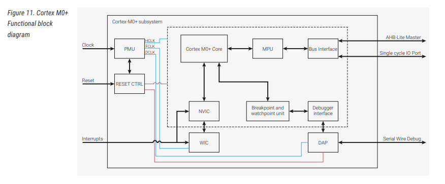
ARM Architecture
The Cortex-M0+ processor is a configurable, multistage, 32-bit RISC processor. It has an AMBA AHB-Lite interface and includes an NVIC component. It also has hardware debug, single-cycle I/O interfacing, and memory-protection functionality. The processor can execute Thumb code and is compatible with other Cortex-M profile processors.
The M0+ features:
• The ARMv6-M Thumb® instruction set.
• Thumb-2 technology.
• An ARMv6-M compliant 24-bit SysTick timer.
• A 32-bit hardware multiplier. This is the standard single-cycle multiplier
• The ability to have deterministic, fixed-latency, interrupt handling.
• Load/store multiple instructions that can be abandoned and restarted to facilitate rapid interrupt handling.
• C Application Binary Interface compliant exception model. This is the ARMv6-M, C Application Binary Interface (CABI) compliant exception model that enables the use of pure C functions as interrupt handlers.
• Low power sleep-mode entry using Wait For Interrupt (WFI), Wait For Event (WFE) instructions, or the return from
interrupt sleep-on-exit feature.
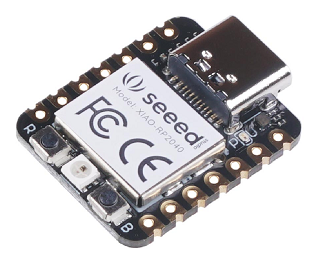
XIAO RP2040
The Seeed Studio XIAO RP2040 is as small as the Seeed Studio XIAO SAMD21 but it's more powerful. On one hand, it carries the powerful Dual-core RP2040 processor that can flexible clock running up to 133 MHz which is a low-power microcontrollers. On the Seeed Studio XIAO RP2040 there is also 264KB of SRAM, and 2MB of on-board Flash memory which can provide more program to save and run. On the other hand, this little board has good performance in processing but needs less power. All in all, it is designed in a tiny size as small as a thumb(20x17.5mm) and can be used for wearable devices and small projects.
There are 14 GPIO PINs on Seeed Studio XIAO RP2040, on which there are 11 digital pins, 4 analog pins, 11 PWM Pins,1 I2C interface, 1 UART interface, 1 SPI interface, 1 SWD Bonding pad interface.
Datasheet
https://files.seeedstudio.com/wiki/XIAO-RP2040/res/rp2040_datasheet.pdf
Specification
|
CPU |
Dual-core ARM Cortex M0+ processor up to 133MHz |
|
Flash Memory |
2MB |
|
SRAM |
264KB |
|
Digital I/O Pins |
11 |
|
Analog I/O Pins |
4 |
|
PWM Pins |
11 |
|
I2C interface |
1 |
|
SPI interface |
1 |
|
UART interface |
1 |
|
Power supply and downloading interface |
Type-C |
|
Power |
3.3V/5V DC |
|
Dimensions |
20×17.5×3.5mm |
Pinout

Software
This time use the Arduino IDE to configure this board. We need to perform some steps to achieve it.
First we need to install the classic Arduino IDE.
Components used:
01 Xiao RP2040
03 LED
Arduino IDE:
The open-source Arduino Software (IDE) makes it easy to write code and upload it to the board. This software can be used with any Arduino board. Active development of the Arduino software is hosted by GitHub. See the instructions for building the code.
Download:
Get the Arduino IDE form its official site.
https://github.com/arduino/Arduino/releases/latest

Installation:
Whe the download was finished, install software. Next, default folder and parameters.

Programming the Xiao RP2040
For programming in the Arduino environment you must add the XIAO RP2040 board to the list in "Boards Manager". To achieve this, you must enter the menu File - Preferences - Additional Boards Manager URLs and add this link: https://github.com/earlephilhower/arduino-pico/releases/download/global/package_rp2040_index.json
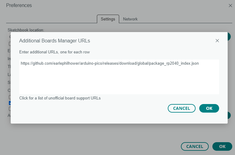
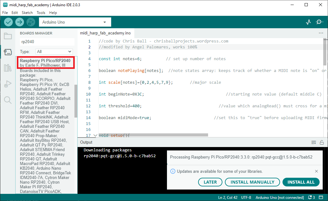
Then navigate to Tools - Board - Boards Manager, and install this Raspberry Pi Pico/RP2040 device.
Finally, we configure the port and board parameters.

Code / Firmware
/*
For the programming of the code I based and modified the original code located in the Arduino IDE examples, "blink". This modification consists of turning on and off 3 LEDs in cycles of 500 milliseconds each.
/*
// the setup function runs once when you press reset or power the board
void setup() {
// initialize digital pins D0, D1 and D2 as an output.
pinMode(D0, OUTPUT);
pinMode(D1, OUTPUT);
pinMode(D2, OUTPUT);
}
// the loop function runs over and over again forever
void loop() {
digitalWrite(D0, HIGH); // turn the LED off by making the voltage HIGH
delay(500); // wait for a half second
digitalWrite(D0, LOW); // turn the LED off by making the voltage LOW
delay(500); // wait for a half second
digitalWrite(D1, HIGH); // turn the LED off by making the voltage HIGH
delay(500); // wait for a half second
digitalWrite(D1, LOW); // turn the LED off by making the voltage LOW
delay(500); // wait for a half second
digitalWrite(D2, HIGH); // turn the LED off by making the voltage HIGH
delay(500); // wait for a half second
digitalWrite(D2, LOW); // turn the LED off by making the voltage LOW
delay(500); // wait for a half second
}
Circuit

Testing

Connecting the Xiao to LEDS to test.
Programming the ESP8266 board
It is possible to program the same cycle using another board, this time, an ESP8266 board.
The ESP8266 is a low-cost Wi-Fi chip with a full TCP/IP stack and microcontroller, manufactured by Espressif, a company based in Shanghai, China. The first chip hit the market around August 2014 with the ESP-01 module, developed by the company AI-Thinker. This small module allows other microcontrollers to connect to a Wi-Fi wireless network and make simple TCP/IP connections using Hayes-style commands. The ESP8266 is like an ESP8266 but with 1MB of internal flash memory, to allow single-chip devices to connect to Wi-Fi. The successor to these modules is the ESP32.
Specs: (Wikipedia)
- 32-bit RISC CPU: Tensilica Xtensa LX106 clocked at 80 MHz
- 64 KB instruction RAM, 96 KB data RAM
- QSPI external flash memory capacity - 512 KB to 4 MB* (can support up to 16 MB)
- IEEE 802.11 b/g/n Wi-Fi
- It has integrated: TR switch, balun, LNA, RF power amplifier and an impedance matching network WEP and WPA/WPA2 authentication support
- 16 GPIO pins (General Purpose Inputs/Outputs)
- SPI, I²C,
- I²S interface with DMA (shares pins with GPIO)
- Dedicated UART pins, plus a transmit-only UART that can be enabled via the GPIO2 pin
- 1 10-bit ADC converter
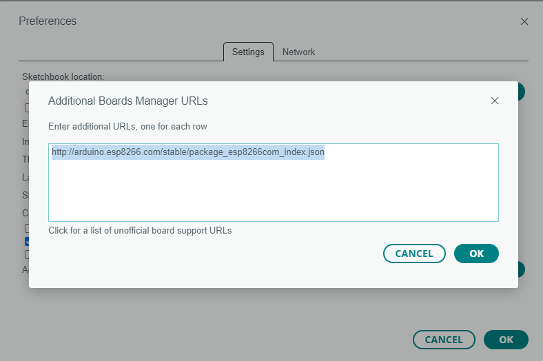
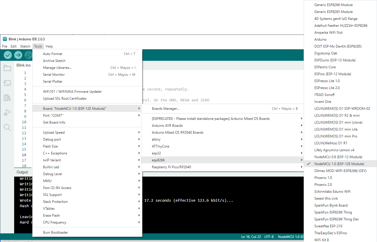
For programming in the Arduino environment you must add the ESP8266 board to the list in "Boards Manager". To achieve this, you must enter the menu File - Preferences - Additional Boards Manager URLs and add this link: http://arduino.esp8266.com/stable/package_esp8266com_index.json
Next, select the board to Arduino IDE
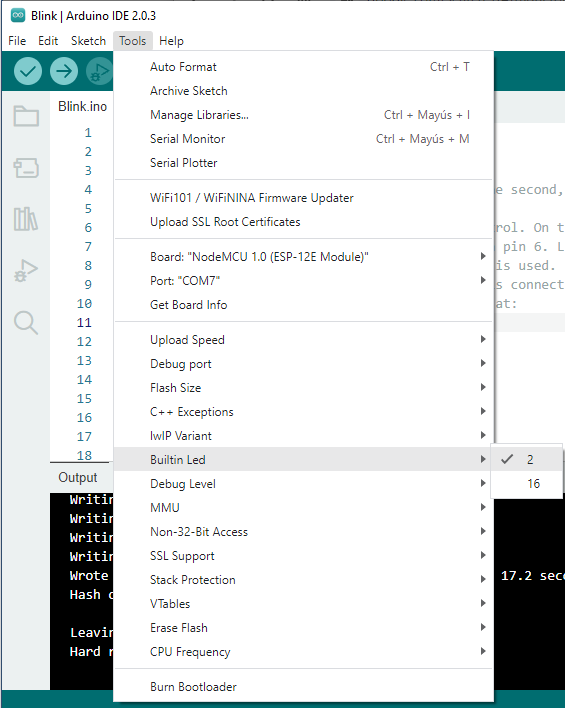
To perform this test we have to open the "blink" example and configure the "Builtin led" parameter located in the Tools menu. We must place pin 2.
Next, I modified the "Blink" example to turn on and off the builtin led for 4 cycles and differente times.
Code/Firmware
/*
Blink
Turns an LED on for one second, then off for one second, repeatedly.
Most Arduinos have an on-board LED you can control. On the UNO, MEGA and ZERO
it is attached to digital pin 13, on MKR1000 on pin 6. LED_BUILTIN is set to
the correct LED pin independent of which board is used.
If you want to know what pin the on-board LED is connected to on your Arduino
model, check the Technical Specs of your board at:
https://www.arduino.cc/en/Main/Products
modified 8 May 2014
by Scott Fitzgerald
modified 2 Sep 2016
by Arturo Guadalupi
modified 8 Sep 2016
by Colby Newman
This example code is in the public domain.
https://www.arduino.cc/en/Tutorial/BuiltInExamples/Blink
*/
// the setup function runs once when you press reset or power the board
void setup() {
// initialize digital pin LED_BUILTIN as an output.
pinMode(LED_BUILTIN, OUTPUT);
}
// the loop function runs over and over again forever
void loop() {
digitalWrite(LED_BUILTIN, HIGH); // turn the LED on (HIGH is the voltage level)
delay(200); // wait for a 200ms
digitalWrite(LED_BUILTIN, LOW); // turn the LED off by making the voltage LOW
delay(200); // wait for a 200ms
digitalWrite(LED_BUILTIN, HIGH); // turn the LED on (HIGH is the voltage level)
delay(500); // wait for a 500ms
digitalWrite(LED_BUILTIN, LOW); // turn the LED off by making the voltage LOW
delay(500); // wait for a 500ms
digitalWrite(LED_BUILTIN, HIGH); // turn the LED on (HIGH is the voltage level)
delay(1000); // wait for a second
digitalWrite(LED_BUILTIN, LOW); // turn the LED off by making the voltage LOW
delay(1000); // wait for a second
digitalWrite(LED_BUILTIN, HIGH); // turn the LED on (HIGH is the voltage level)
delay(1500); // wait for a 1500ms
digitalWrite(LED_BUILTIN, LOW); // turn the LED off by making the voltage LOW
delay(1500); // wait for a 1500ms
}
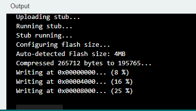
The way of programming is the typical conventional Arduino one (Sketch - Upload menu), however we can notice differences in the output section.
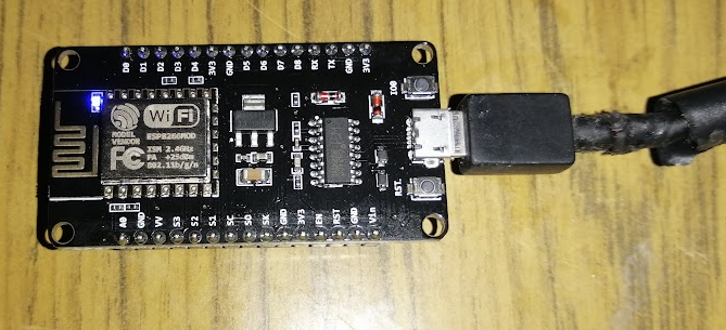
The blue builtin led is shown in the board.
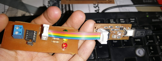
Programming ATtiny85 using FabISP
In this section I've found a difference for programming the ATtiny85, this is because I used the FabISP that I've make in Assignment 4: Electronics Production
Next, open the Arduino IDE, and select File, Samples, 01. Basics, Blink.
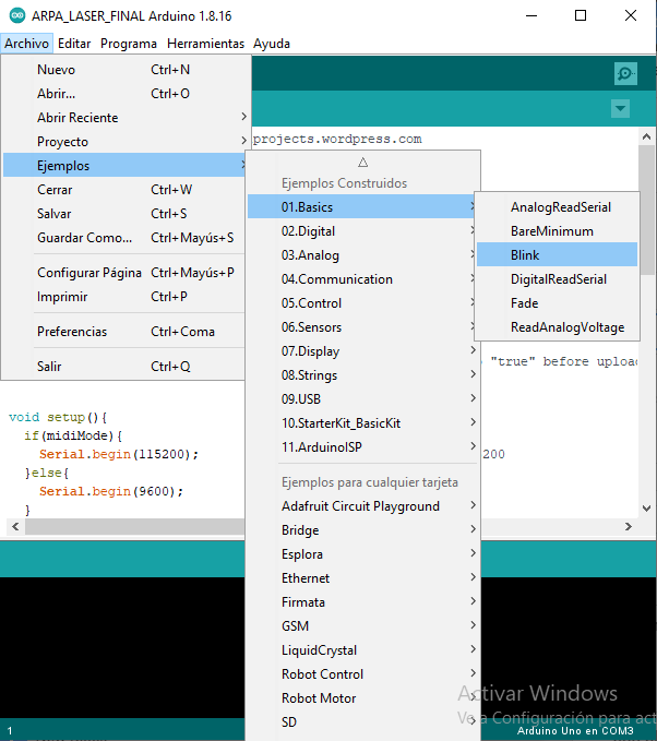
A blink led sample code was opened.

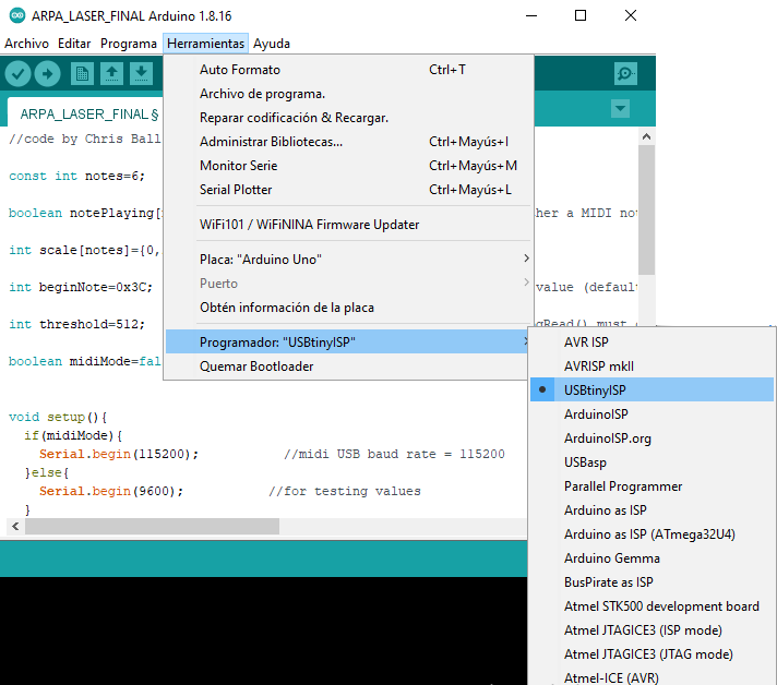
To use the ICSP programmer we need to select it. Go to Tools menu, Programmer, USBTinyISP
Code/Firmware
Next, I modified the "Blink" example to turn on and off 3 color leds for 200 milliseconds of time.
/*
Blink
Turns an LED on for one second, then off for one second, repeatedly.
Most Arduinos have an on-board LED you can control. On the UNO, MEGA and ZERO
it is attached to digital pin 13, on MKR1000 on pin 6. LED_BUILTIN is set to
the correct LED pin independent of which board is used.
If you want to know what pin the on-board LED is connected to on your Arduino
model, check the Technical Specs of your board at:
https://www.arduino.cc/en/Main/Products
modified 8 May 2014
by Scott Fitzgerald
modified 2 Sep 2016
by Arturo Guadalupi
modified 8 Sep 2016
by Colby Newman
This example code is in the public domain.
https://www.arduino.cc/en/Tutorial/BuiltInExamples/Blink
*/
// the setup function runs once when you press reset or power the board
void setup() {
// initialize digital pin LED_BUILTIN as an output.
pinMode(0, OUTPUT);
pinMode(1, OUTPUT);
pinMode(2, OUTPUT);
}
// the loop function runs over and over again forever
void loop() {
digitalWrite(0, HIGH); // turn the LED on (HIGH is the voltage level)
delay(200); // wait for a 200ms
digitalWrite(0, LOW); // turn the LED off by making the voltage LOW
delay(200); // wait for a 200ms
digitalWrite(1, HIGH); // turn the LED on (HIGH is the voltage level)
delay(200); // wait for a 200ms
digitalWrite(1, LOW); // turn the LED off by making the voltage LOW
delay(200); // wait for a 200ms
digitalWrite(2, HIGH); // turn the LED on (HIGH is the voltage level)
delay(200); // wait for a 200ms
digitalWrite(2, LOW); // turn the LED off by making the voltage LOW
delay(200); // wait for a 200ms
}
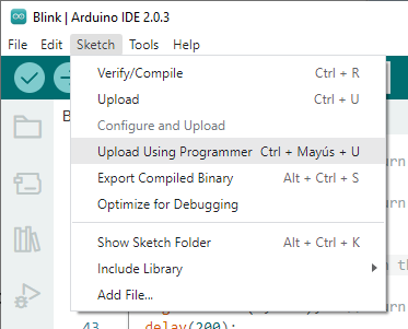
So, for upload the code, I've chose the "Upload using programmer" option.
Serial Monitor Test
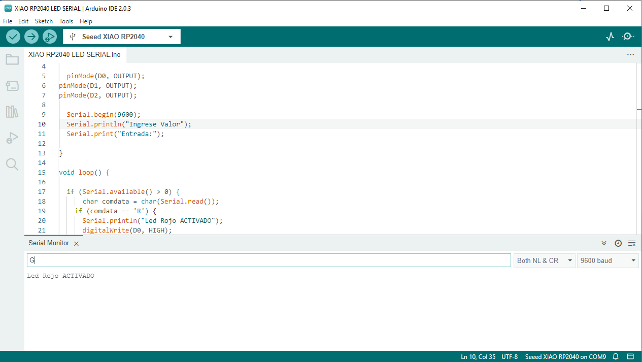
Next I made a code (using Xiao RP2040) where when sending a character to the serial console, an LED of its respective color is activated.
void setup() {
pinMode(D0, OUTPUT);
pinMode(D1, OUTPUT);
pinMode(D2, OUTPUT);
Serial.begin(9600);
Serial.println("Ingrese Valor");
Serial.print("Entrada:");
}
void loop() {
if (Serial.available() > 0) {
char comdata = char(Serial.read());
if (comdata == 'R') {
Serial.println("Led Rojo ACTIVADO");
digitalWrite(D0, HIGH);
}
if (comdata == 'G') {
Serial.println("Led Verde ACTIVADO");
digitalWrite (D1, HIGH);
}
if (comdata == 'Y') {
Serial.println("Led Amarillo ACTIVADO");
digitalWrite (D2, HIGH);
}
}
}
Then, open Tools menu - Serial Monitor. So, a Serial monitor window appeared, where I have 3 options to write, R to turn on Red led, G to Green led and Y for Yellow led. A baud rate is set to 9600 baud on the code. Check if is the same on the Serial Monitor window.
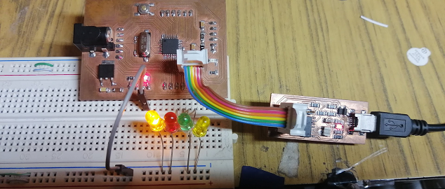
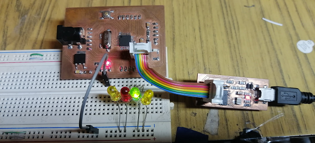
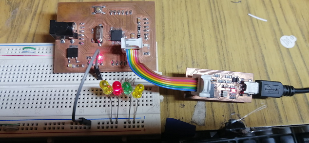
Programming the Fabduino Board
In the same way mentioned above in the Arduino IDE we place the following code to turn on 04 LEDs using the Fabduino board through the FabISP.
//Blink code example modified for 04 leds
// the setup function runs once when you press reset or power the board
void setup() {
// initialize digital pin LED_BUILTIN as an output.
pinMode(10, OUTPUT);
pinMode(11, OUTPUT);
pinMode(12, OUTPUT);
pinMode(13, OUTPUT);
}
// the loop function runs over and over again forever
void loop() {
digitalWrite(10, HIGH); // turn the LED on (HIGH is the voltage level)
delay(500); // wait for a second
digitalWrite(10, LOW); // turn the LED off by making the voltage LOW
delay(500); // wait for a second
digitalWrite(11, HIGH); // turn the LED on (HIGH is the voltage level)
delay(1000); // wait for a second
digitalWrite(11, LOW); // turn the LED off by making the voltage LOW
delay(1000); // wait for a second
digitalWrite(12, HIGH); // turn the LED on (HIGH is the voltage level)
delay(1000); // wait for a second
digitalWrite(12, LOW); // turn the LED off by making the voltage LOW
delay(1000); // wait for a second
digitalWrite(13, HIGH); // turn the LED on (HIGH is the voltage level)
delay(1000); // wait for a second
digitalWrite(13, LOW); // turn the LED off by making the voltage LOW
delay(1000); // wait for a second
}
Testing Fabduino