Electronics Production
Testing Traces
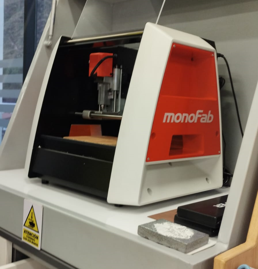
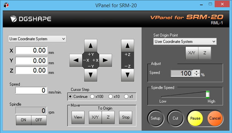
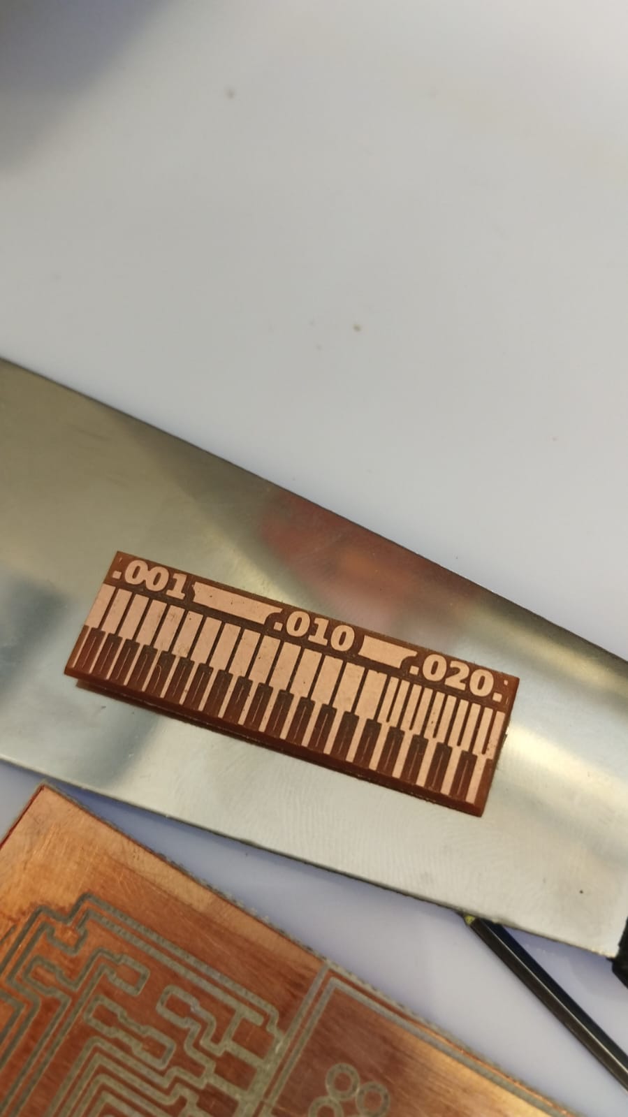
This time we will do the track thickness test that the machine can perform, in this case, a Roland model SRM20.
Link: https://www.rolanddga.com/es/productos/3d/srm-20-fresadora-compacta
Some specs:
Cuttable Material: Modeling Wax, Chemical Wood, Foam, Acrylic, Poly acetate, ABS, PCB board
X, Y, and Z Operation Strokes: 8 (X) x 6 (Y) x 2.38 (Z) inches, 203.2 (X) x 152.4 (Y) x 60.5 (Z) mm
Workpiece table size: 9.14 (X) x 6.17 (Y) inches, 232.2 (X) x 156.6 (Y) mm
Distance From Collet Tip to Table: Maximum, 5.15 in (130.75mm)
Loadable Workpiece Weight: 4.4 lbs (2kg)
X-, Y-, and Z-Axis Drive System: Stepping motor
Operating Speed: 0.24 – 70.87inch/min, 6 – 1800mm/min
Software Resolution: 0.000039 inches/step (RML-1), 0.000039 inches/step (NC code), 0.01 mm/step (RML-1), 0.001mm/step (NC code)
Mechanical Resolution: 0.0000393 inches/step, 0.000998594 mm/step
Spindle Motor: DC motor Type 380
Spindle Rotation Speed: Adjustable 3,000 – 7,000 rpm
Cutting Tool Chuck: Collet method
Interface: USB
Control Command Sets: RML-1, NC code
Power Requirements: Machine: DC24V, 2.5A,
Dedicated AC adapter: AC 100-240V ±10%, 50/60Hz
Power Consumption: Approx. 50W
Operating Noise: During operation: 65 dB (A) or less (when not cutting), during standby: 45 dB (A) or less
External Dimensions: 17.76 (W) x 16.80 (D) x 16.78 (H) inches, 451.0 (W) x 426.6 (D) x 426.2 (H) mm
Weight: 43.2 lbs, 19.6 kg
Installation Environment: Temperature of 41 to 104 °F (5 to 40°C), 35 to 80% relative humidity (no condensation)
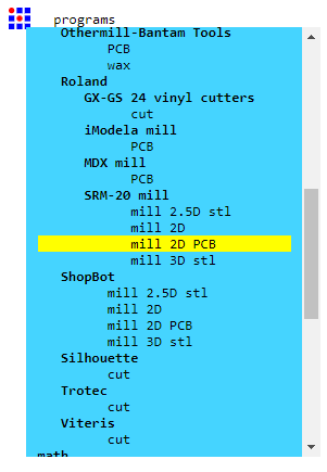
To carry out these tests we enter the Fab Academy Mods CE Project page: https://modsproject.org.
Then, I choose the the program Roland, SRM20 mill, mill 2D PCB.
This is general view.
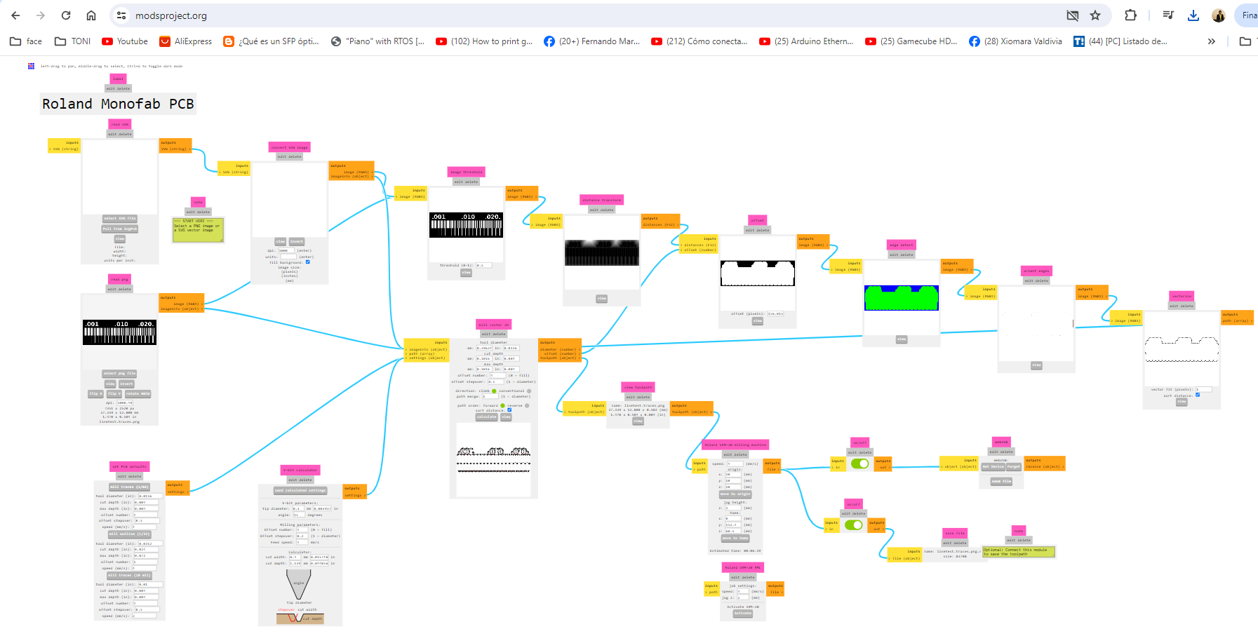
Then we need to configure the circuit to cut, the cutter, the speeds, etc.
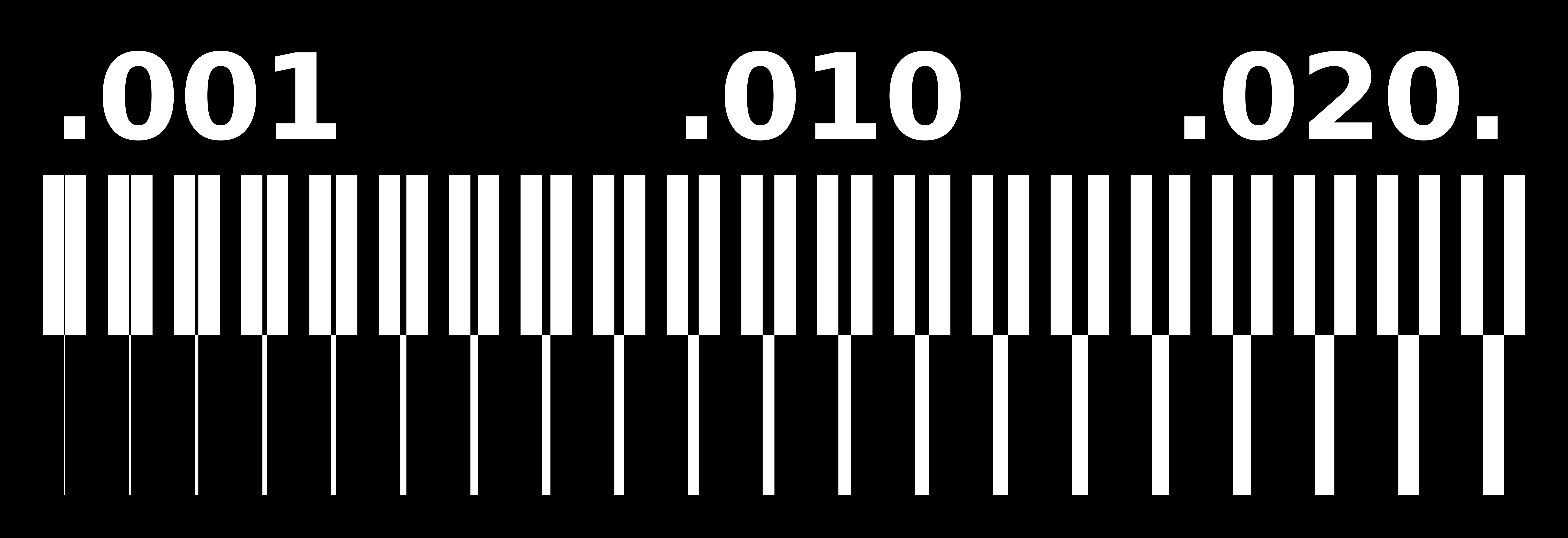
First, we select our Fab Academy test image. https://academy.cba.mit.edu/classes/electronics_production/linetest.traces.png

Next, in Mods CE website, https://modsproject.org/. Then select png file (linetest.traces.png)
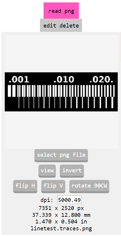
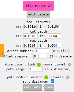
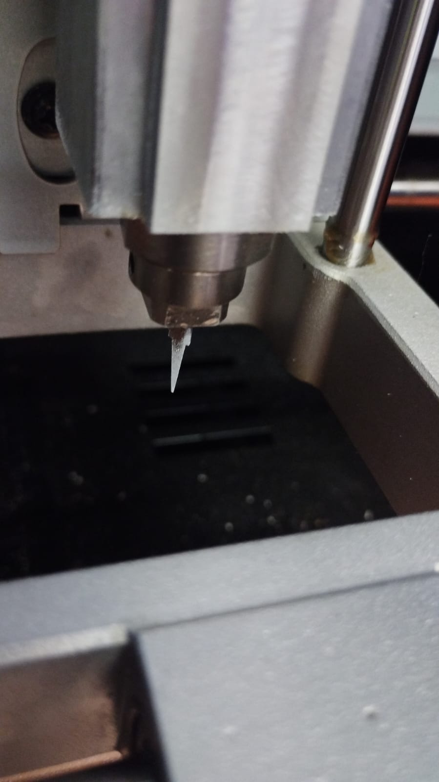
Next, verify the v-bit (in my case 0.1mm, 30 degrees)
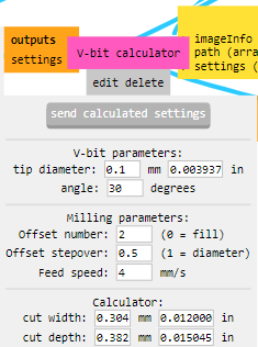
Check the speeds, I used 2.5mm/s
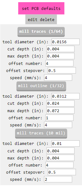
Next, for milling PCB I used the "2mill traces (1/64)" settings.
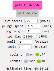
Next, configure set origins x:0, y:0, z:0 to the machine.
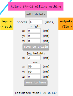
Finally, I choose the calculate option to generate the RML file for cutting.
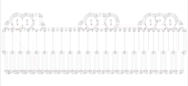
These are the milling routes of the test file.
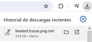
The file generated in download folder.
In the Vpanel for SRM20, load the RML pressing Cut button.
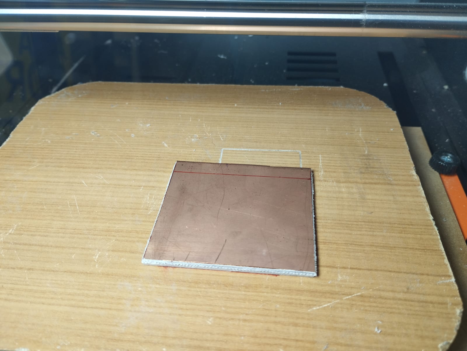
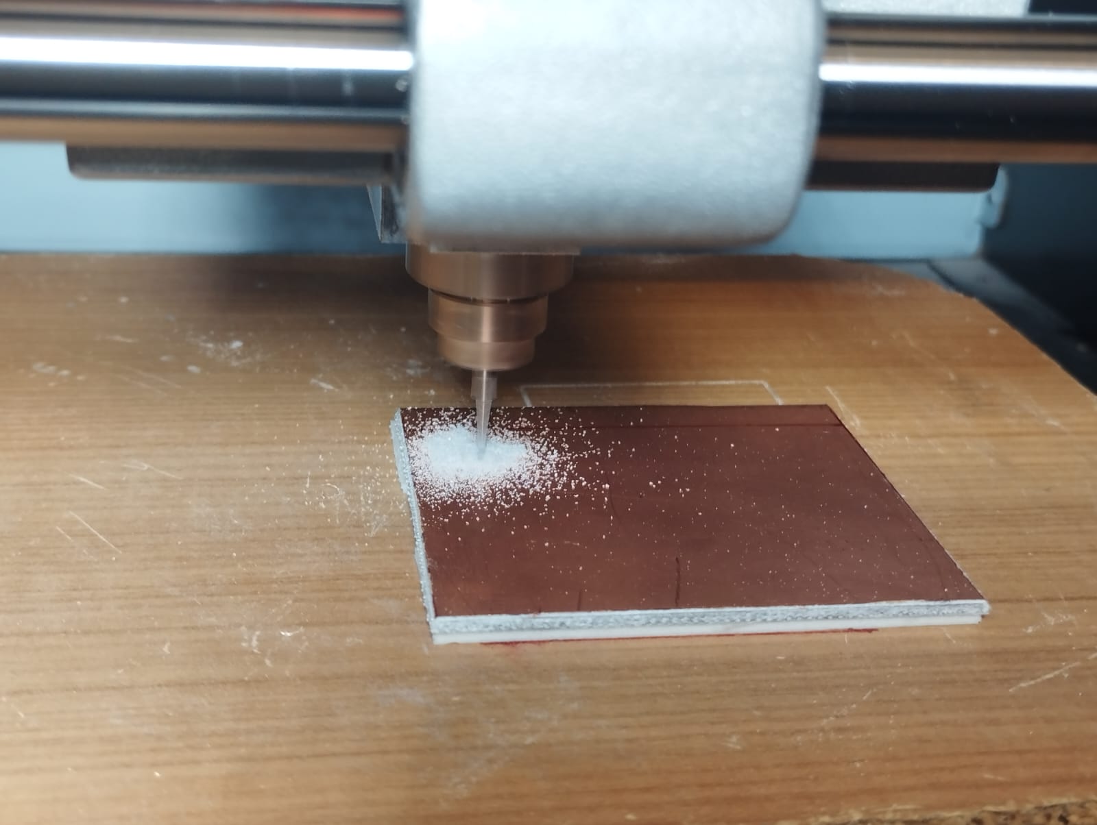
So, I chose a PCB board that was as flat as possible to avoid future cutting errors.
I choose the v-bit 0.1mm, 30 degrees.
Afterwards, double contact is used to fix the plate on the platform
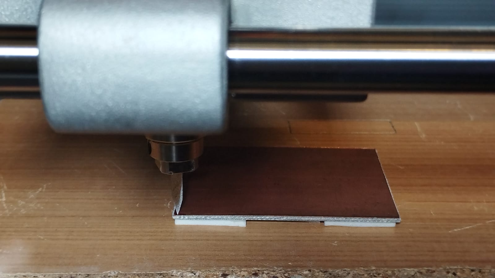
Once the process was done, I noticed that there were some imperfections in the smaller tracks.
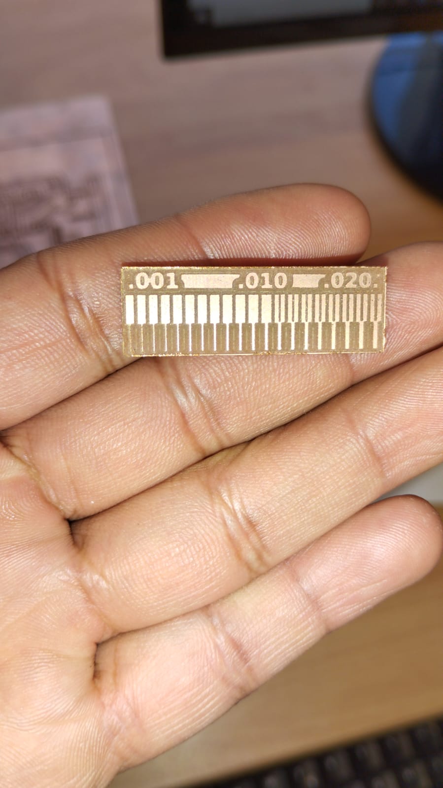
So I decided to place a double contact tape in the center of the PCB board to make it as level as possible.
I repeated the process again and obtained a better cutting result.
Making the ISP
I used ATtiny44 microcontroller as programmer for FabISP. I followed this document to program the firmware.
I follow this guide to make a FabISP http://fab.cba.mit.edu/content/archive/projects/fabisp/
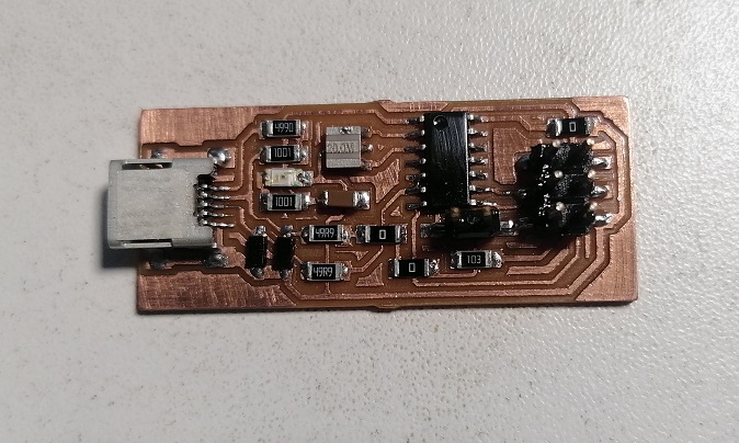
This is the PCB board:
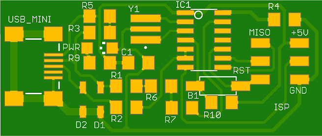
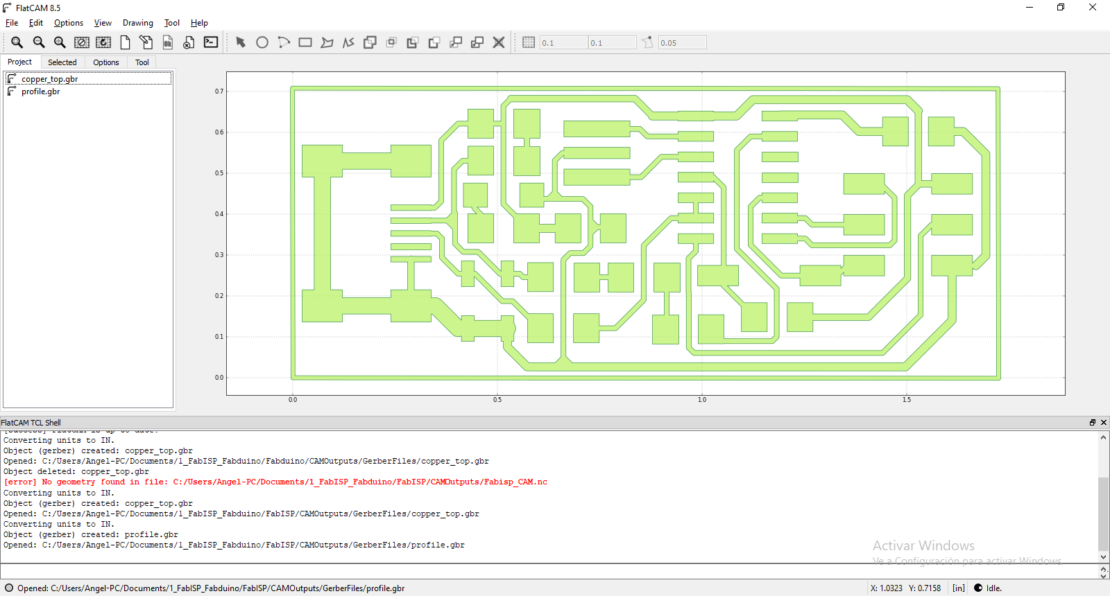
I used FlatCam software to open the gerber files. I selected the copper top and profile layers.
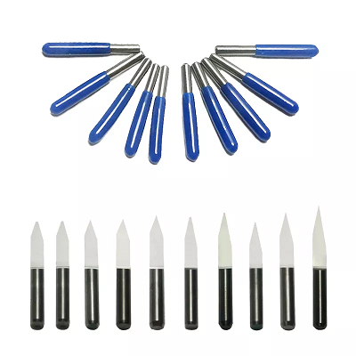
To make the FabISP board I chose this 3.175 mm shaft diammeter , 20º angle (according to the manufacturer), 0.5 mm cutting diammeter V-shape mill.
Then I changed some parameter on FlatCam for milling the PCB. 20 degrees angle was configurated, v-tip so close to 0.5 because I need for milling the copper 35 microns.
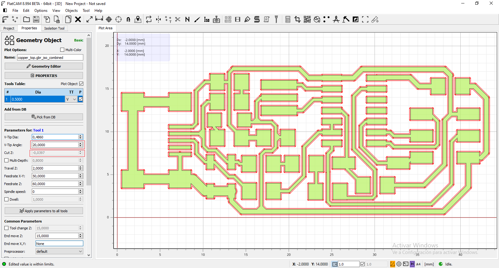
Then, I saved the changes for generating the paths, g-code file.

Similar configuration for the profile cutting, but I used a standard milling tool.
Tool diammeter and speed was changed for profile cutting. A little gap was configured for easy removing the board.
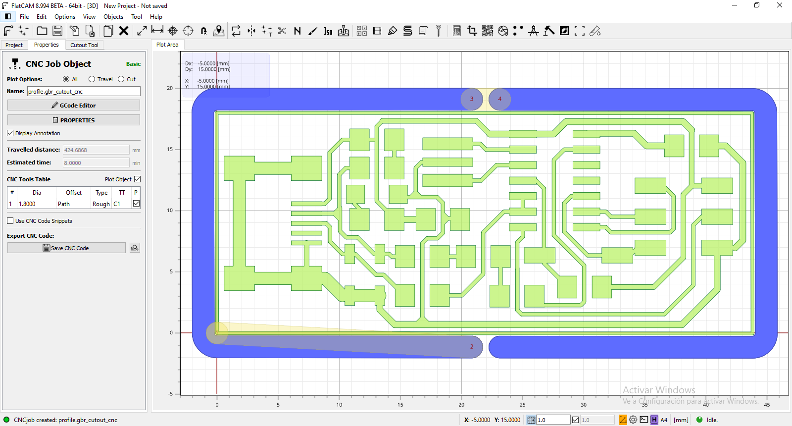
Next, G-code file was generated!
Then, I used MACH4 for controlling the machine.
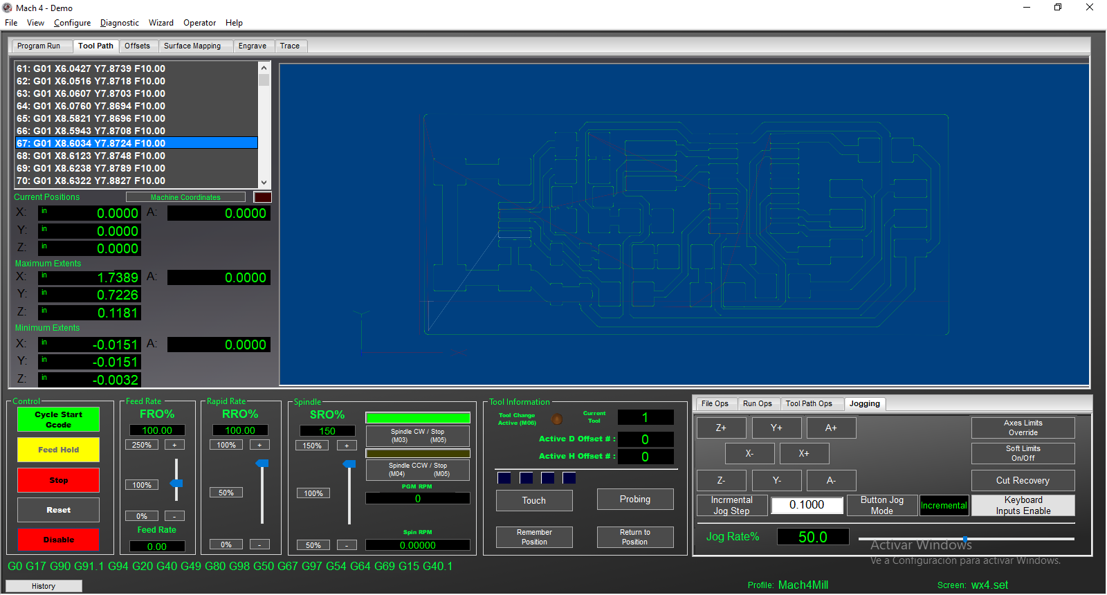
It shows the gcode lines and the paths for milling. Then, Cycle Start Gcode button was pressed to start milling!
Milling the PCB
I used a miniCNC router to milling the PCB.
My setup is:
Machine: MiniCNC 3040
Link: https://www.ebay.com/itm/333380911663
Brand: China CNC Zone
Controller: MACH4 (Lifetime Licensed)
Speed: 24000 RPM Spindle
Mill: v-shaped engraving bit 0.5mm
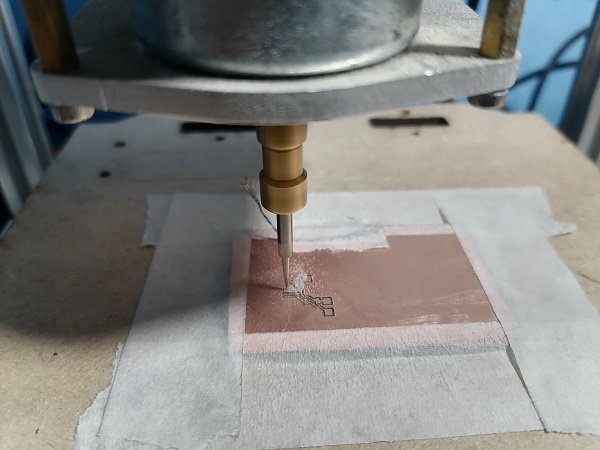
Process start

We use masking tape to fix the pcb on the platform
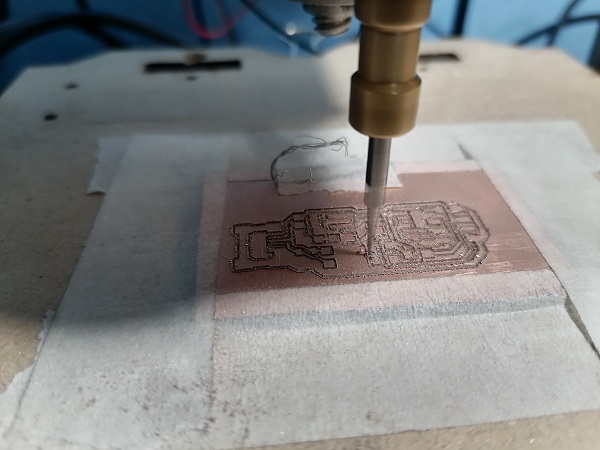
Finishing the milling
Components used
01 x ATtiny44 SMD
01 x miniUSB connector
02 x resistor 1K ohm
01 x resistor 499 ohm
02 x resistor 49 ohm
01 x resistor 499 ohm
01 x green LED
01 x red LED
01 x USB Type A
01 x jumper 02x03
01 x jumper
02 x zener diode 3.3V
01 x capacitor 100n
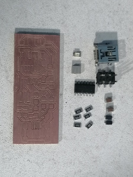
Components ready to solder
I have performed several tests to determine a good result.
It is very important that before welding we verify that there are no short circuits and verify The width of the track corresponds to the design.
I chose this board, the FabISP 2017, because I have those components in the Fab Lab inventory, because due to a logistics problem it would take too long to arrive.
Perhaps I would have had to redesign the board to use another type of connector.
Connecting board to the PC
When the board was connected to the PC through USB port, a new devide was detected. It means missing driver.
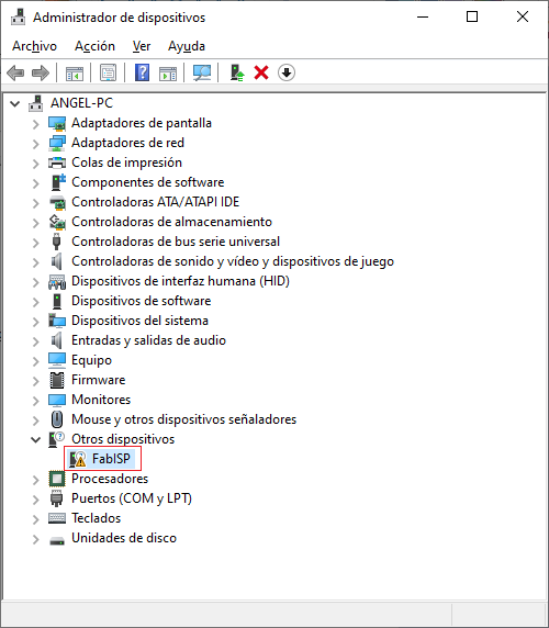
Then, I downloaded the USBTiny (Adafruit) driver for this device. This is the link: https://learn.adafruit.com/usbtinyisp/drivers
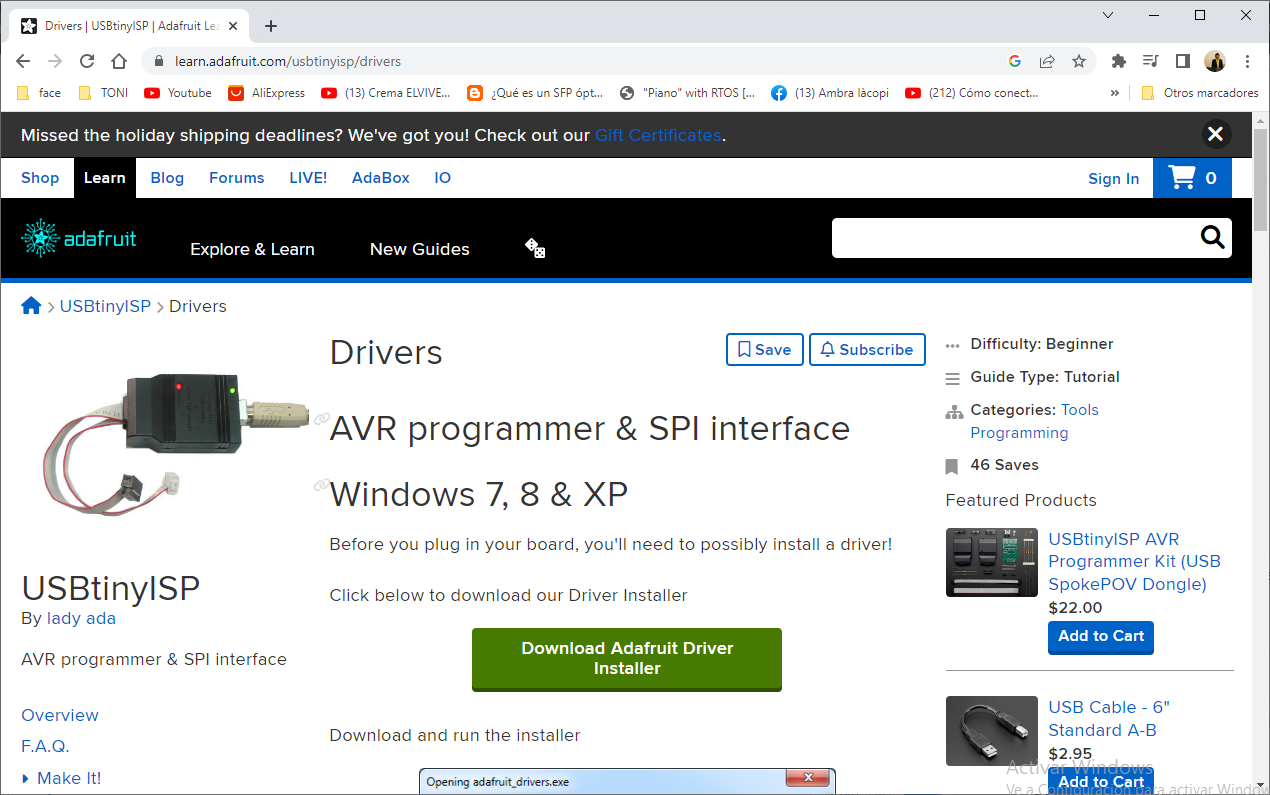
Then, I clicked on the link to download it. (adafruit_drivers_2.5.0.0.exe)
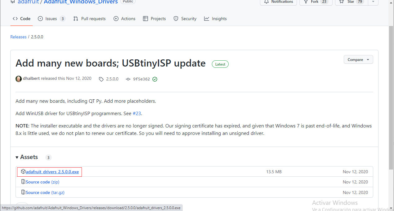
Next, I've installed the drivers.

Then, the FabISP is correctly installed.

Testing the FabISP
I used this FabISP to program a Attiny85 PCB to make a led sequence. I used my old PCB for test purposes.
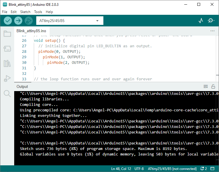

For programming I used the ISP connector.
 The FabISP works!
Problems and solutions
*The PCB board is often not completely flat, this was solved by applying masking tape to fix it better.
*The MACH4 software interface may seem a little complex, however, it only requires configuring some important parameters for its correct operation.
Download
Download files
Sending PCB to a Board House
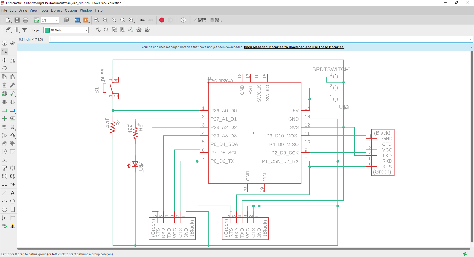
I have decided to send my Fab Xiao PCB board design to a board house.
I developed my PCB board design in Autodesk's Eagle software.
Load the schematic file
Load the board file
Next, I needed to export data in Gerber format for processing in the PCBgogo.
I selected File - CAM processor.
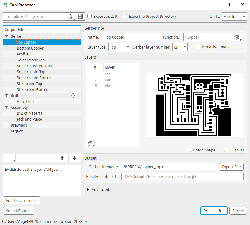
Next, I selected a new folder to export, then Process Job
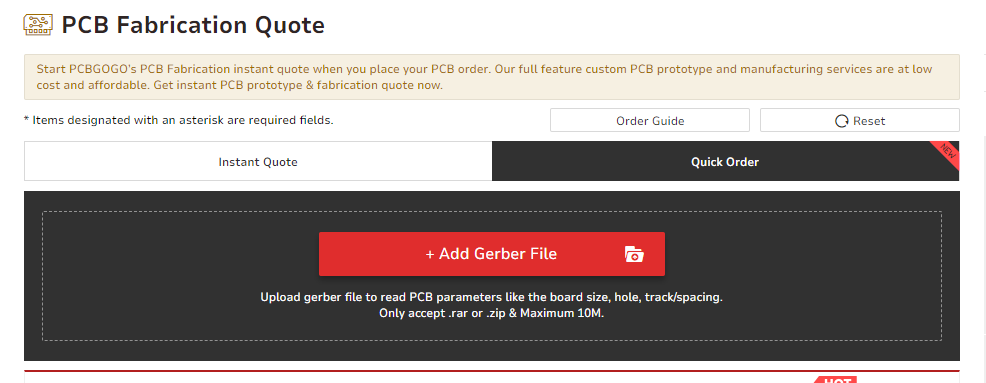
So, the website only accept the files in zip or rar format.

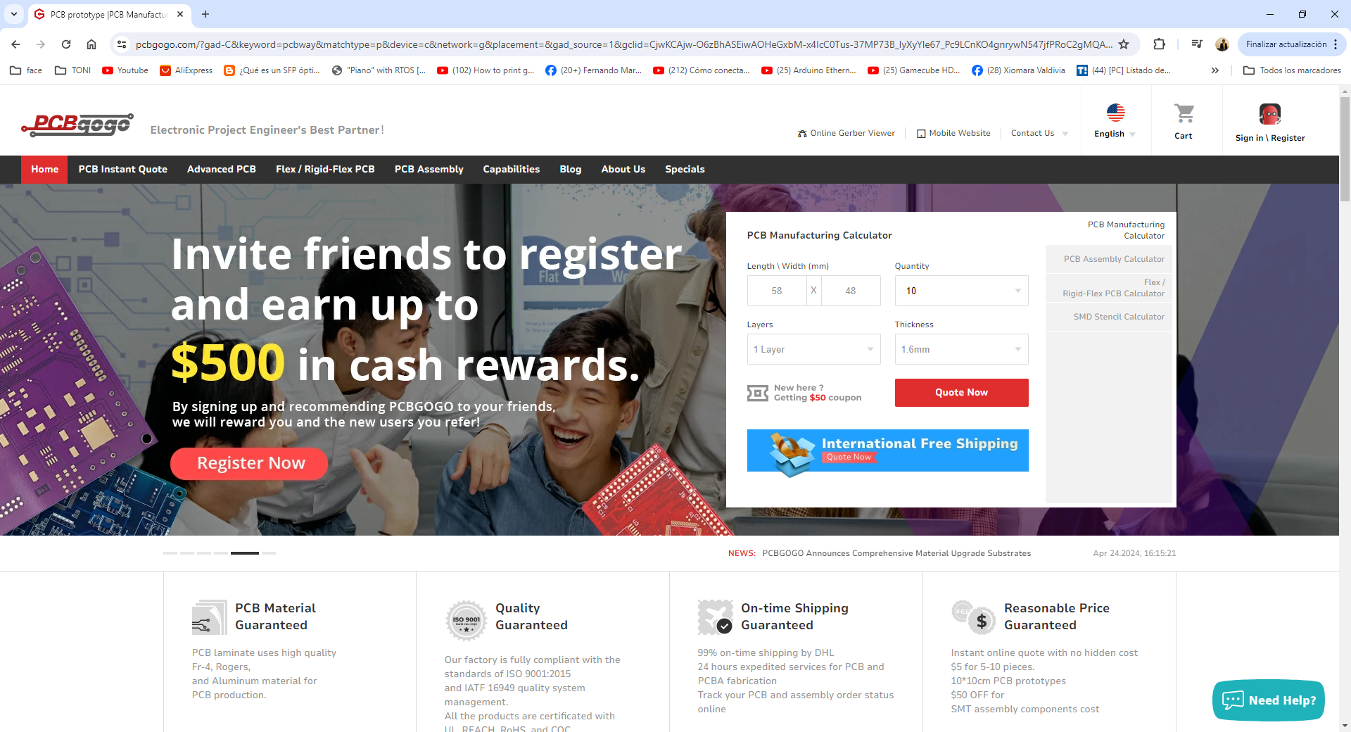
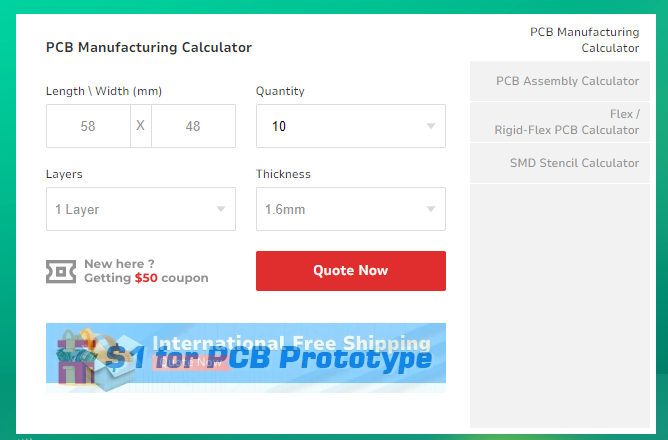
Now, in PCBgogo website go to PCB Manufacturing section and type the size of board, quantity, numer of layers and thinkness. Then, Quote Now.
 Next, go to Quick order and upload the rar or zip file with the gerber files.
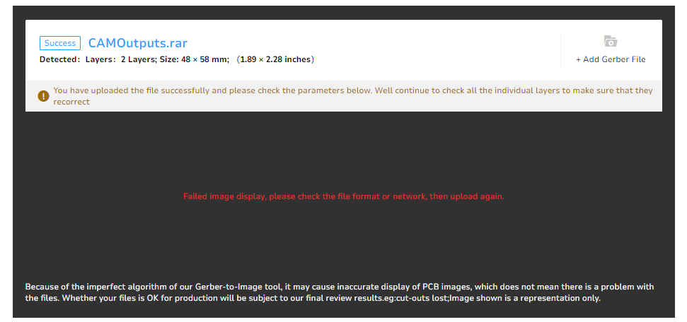
Upload Successful showing some information of the design
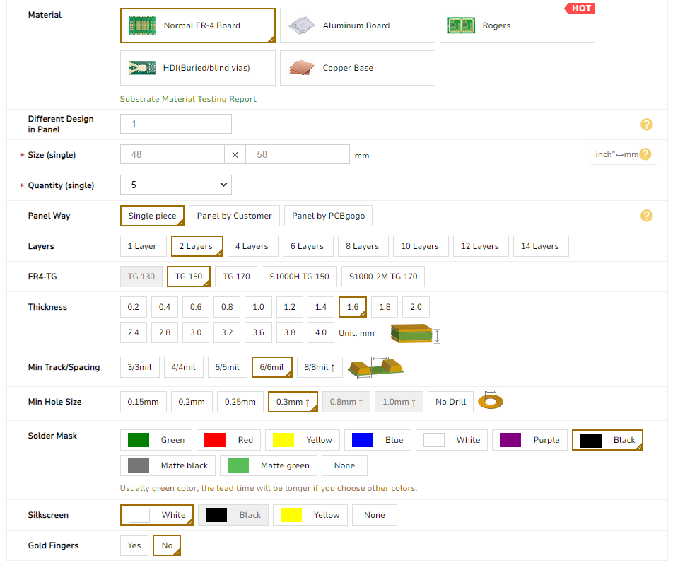
Next, I selected some options for fabrication, material, color, etc.
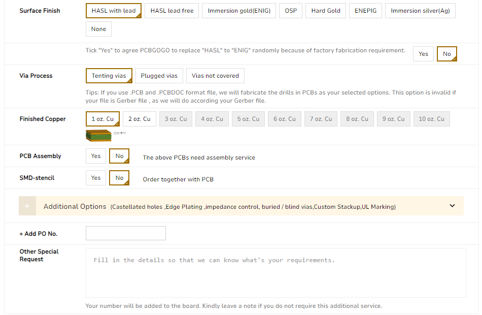
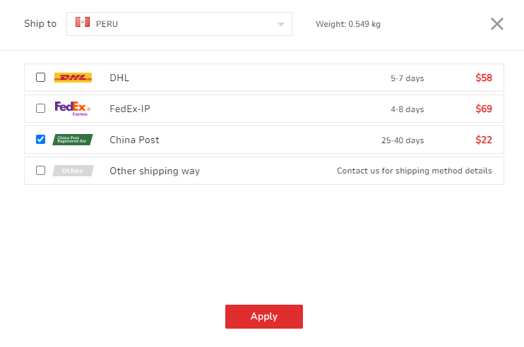
Next, I confugured the shipping options for my country. Then, Apply.
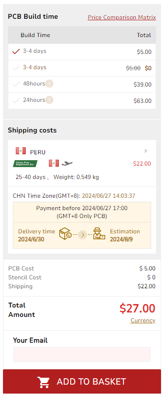
Finally, it show the PCB Build time and total amount.
Takeaways assignment:
- Because I am in another campus of the university, I did this activity alone.
- In this assignment I was able to verify how easy and fast it is to make an ISP-type programmer. However, unlike DIP boards, there are some considerations to be taken when making SMD boards.
- I think it is very important to have a programmer to program microcontrollers in general using ISP in any type of project.
- In the milling process, some very important issues must be taken into account, such as the leveling of the PCB board and the edge of the milling cutter to obtain optimal results.
- For me it helps me to make modifications and firmware updates quickly