Computer Controlled Cutting
Laser Cutting
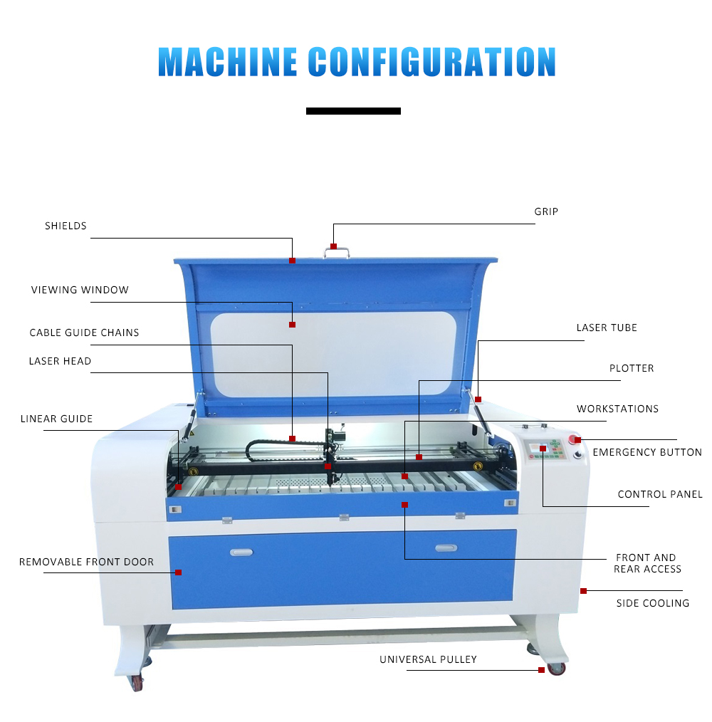
Laser Cutter Specs: 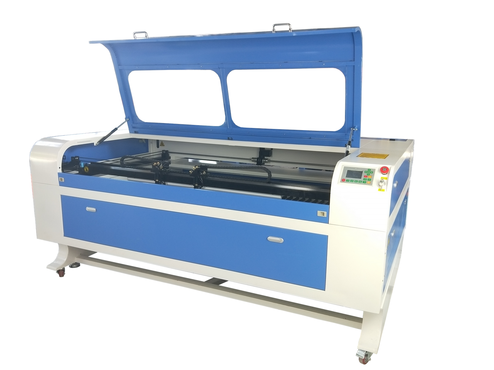
Autofocus Laser Head: Precision stepper motor industrial laser head with red light and blow function, autofocus, and CCD function can be installed.
High Power Co-Laser Tubes: Metal end and glass direct sintering process, beam stability, high power, cost effective.
Intelligent Control Systems: Visual operating panel with synchronized display of cutting graphics, speed, time, power, etc.
Large Format Plotter: Genuine imported limit switches, stable quality, cellular platform and cutter bar platform available.
Precision steppers motors: Adopt 57 Rexroth stepping motor, precise positioning, low noise, fast lifting, low vibration resistance.
Precision Linear Guides: Sturdy and durable, low friction, low operating resistance, effective increase in working speed..
Working Photos: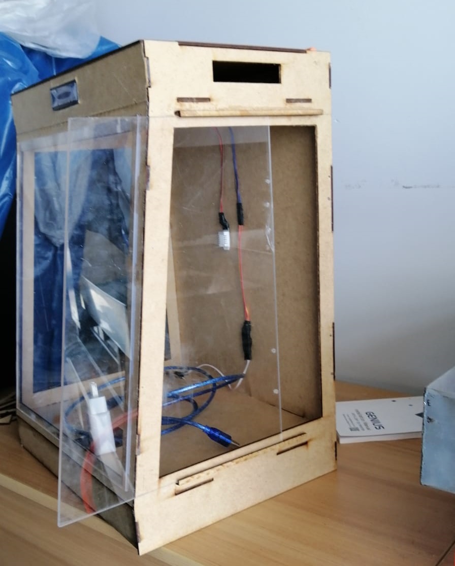
RDWorks Software:
RDWorks enables users to perform laser cutting and engraving operations. The software allows you to create lines, shapes, Bezier curves and text. It also uses a number of vector formats (such as .dxf, .ai and .plt ) and raster formats (such as .bpm, .jpg, .gif and .png).
- Control of the machines speed and power settings via the software interface
- Programming of independent layers for different speed and power settings
- Basic drawing functions
- Basic edit functions such as move, resize, mirror and offset
- Work simulation and preview
- Compatible with Windows XP – 10. 32 and 64 bit available
- Low CPU and RAM usage
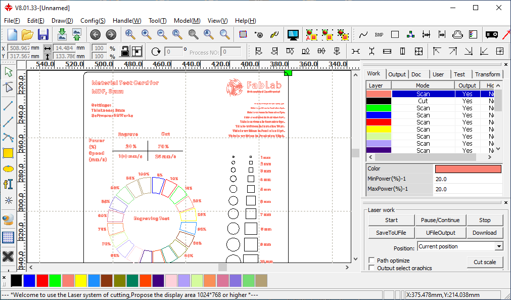
This machine uses RDWorks software to edit, prepare, configure the parameters for cutting. Also it can export into a file to load on the machine to start to cut, 
Even it has a simulator for previewing the cutting/engraving process.
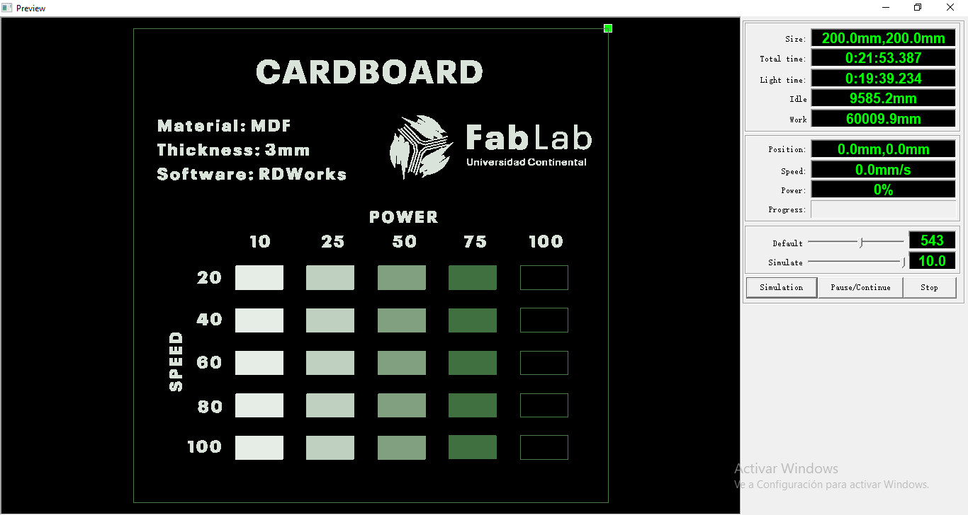
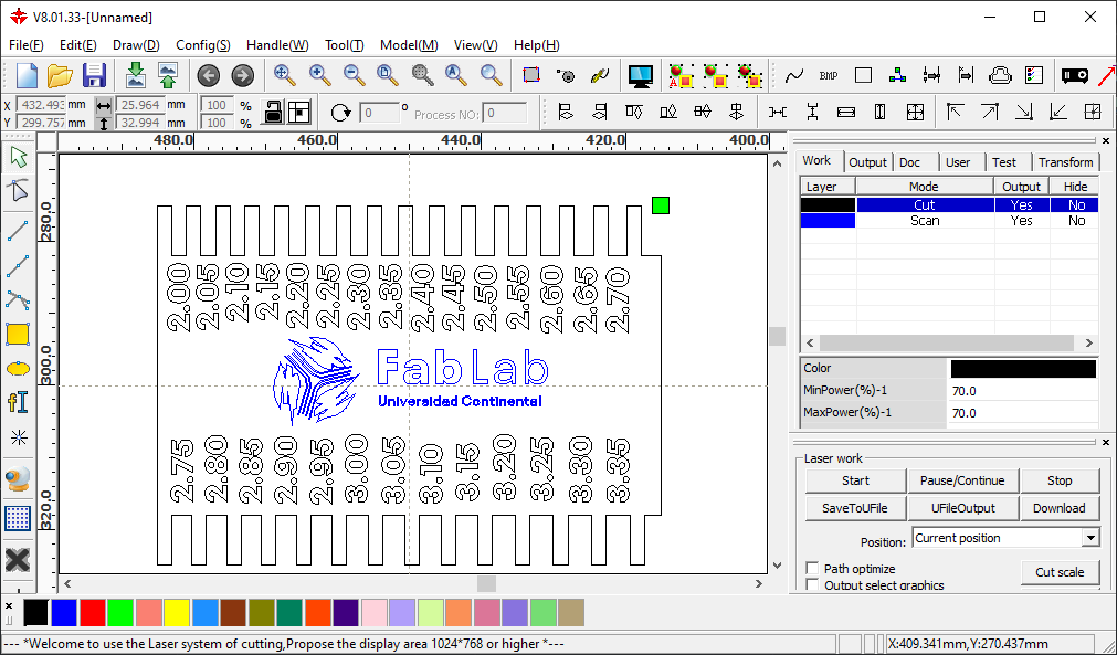
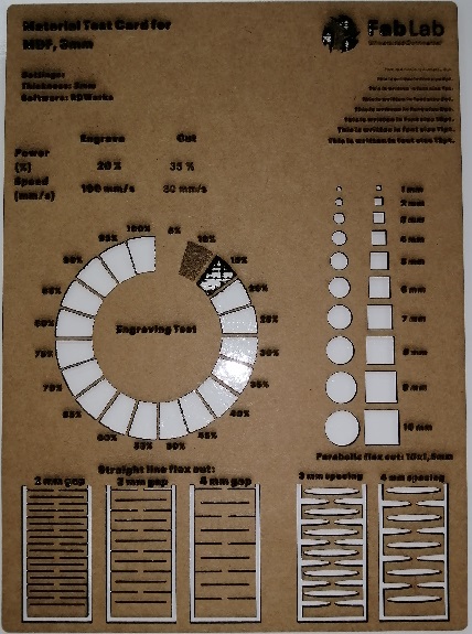
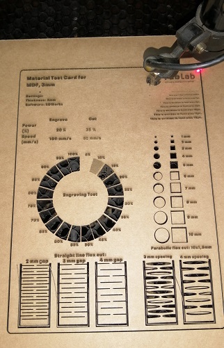
AutoCAD software was used to modify a template to test power and speed parameters of laser cutting/engraving.
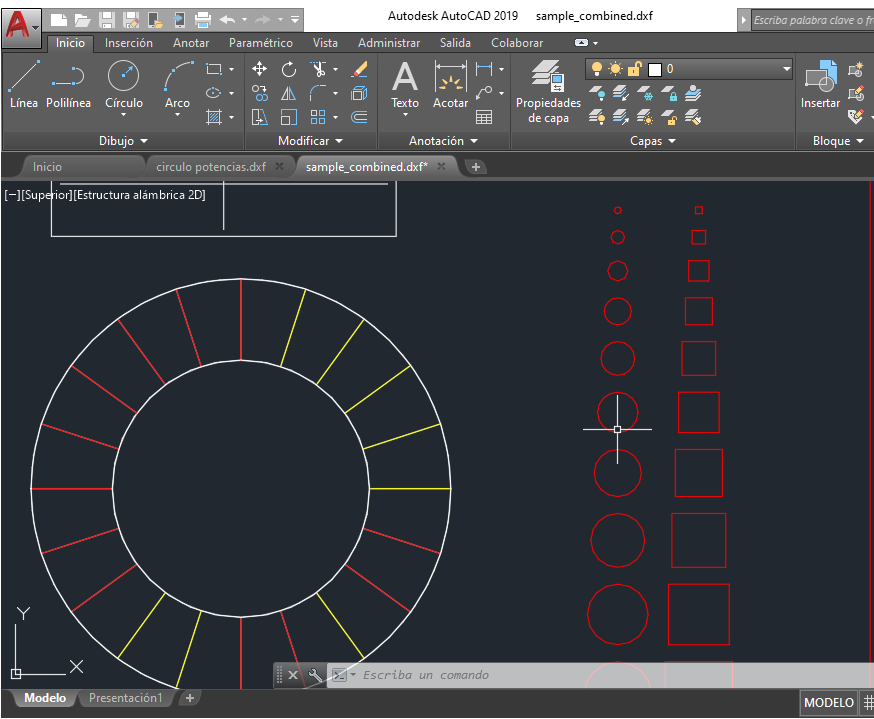
Then the design was exported in DXF format to open it in RDWorks, like image shown below.
Same case for joints test.
Results:
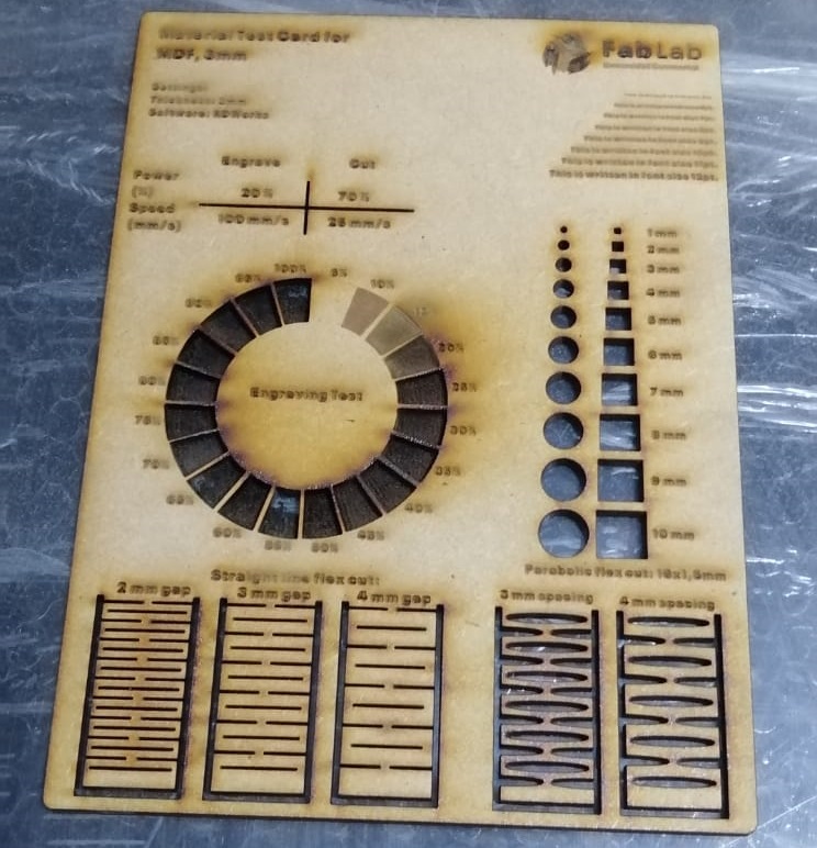
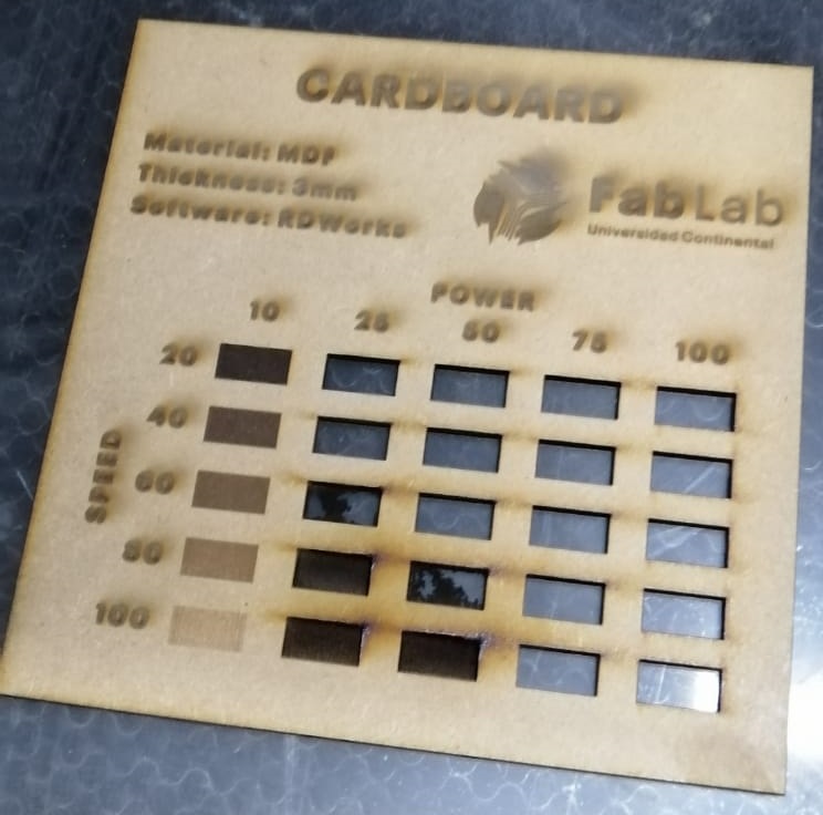
The material for test was MDF, 3mm of depth.
Cut parameters: Speed: 25mm/s Power: 70%
Engraving parameters: Speed: 100mm/s Power: 20%
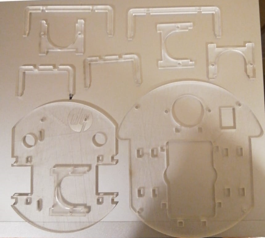
3mm MDF:
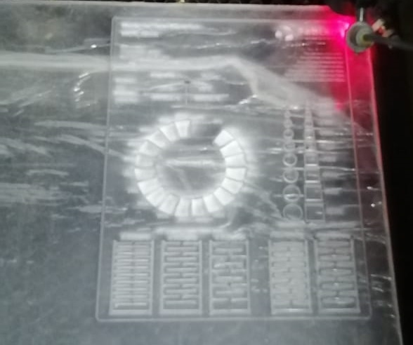
3mm Transparent Acrylic:
2mm corrugated cardboard:
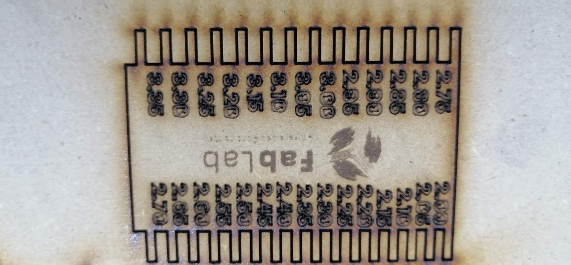
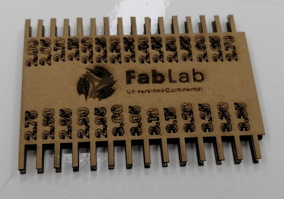
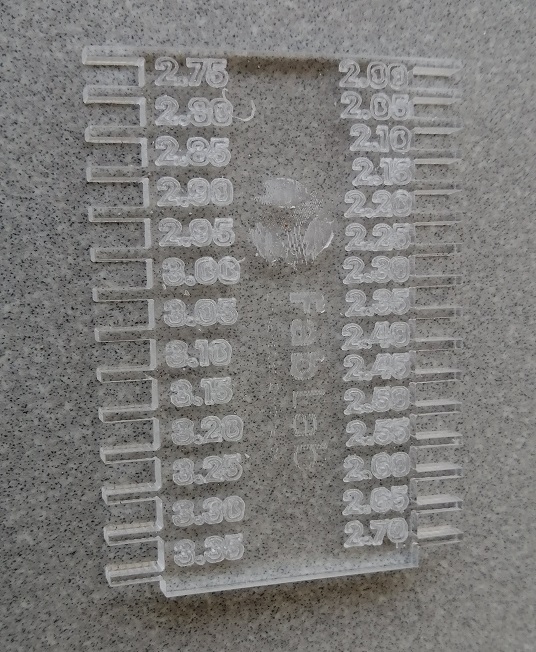
Testing the milimetrical precision:
with MDF (3mm):
with corrugated cardbox (3mm):
with acrylic (3mm):
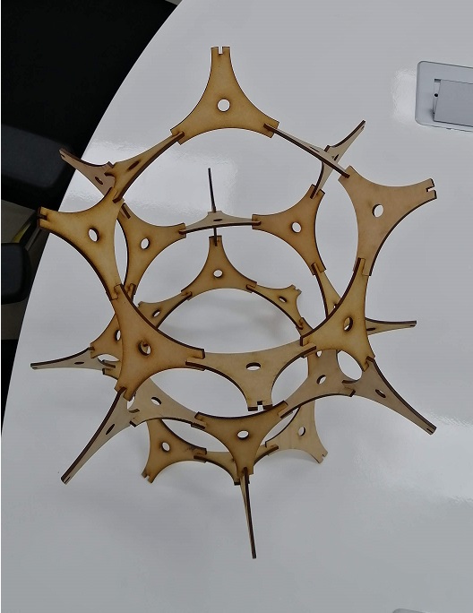
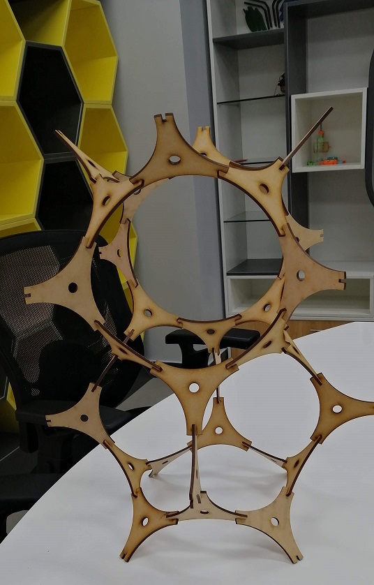
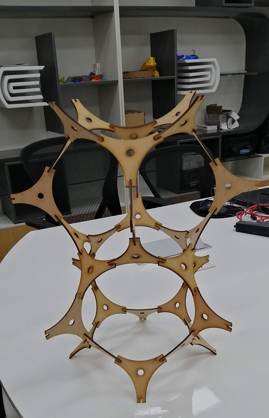
Pressfit Construction Kit:
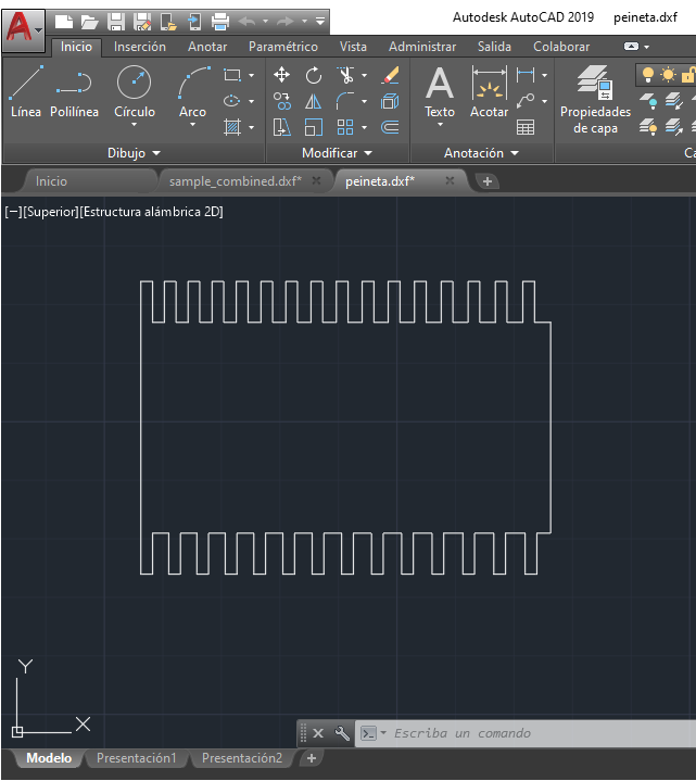
A design was made in Autodesk Autocad, it's a interesting piece to build diferent structures!
Set up 3mm kerf for junctions.
I used MDF 3mm, then in RDWorks I set speed 30 mm/s and power 35%.
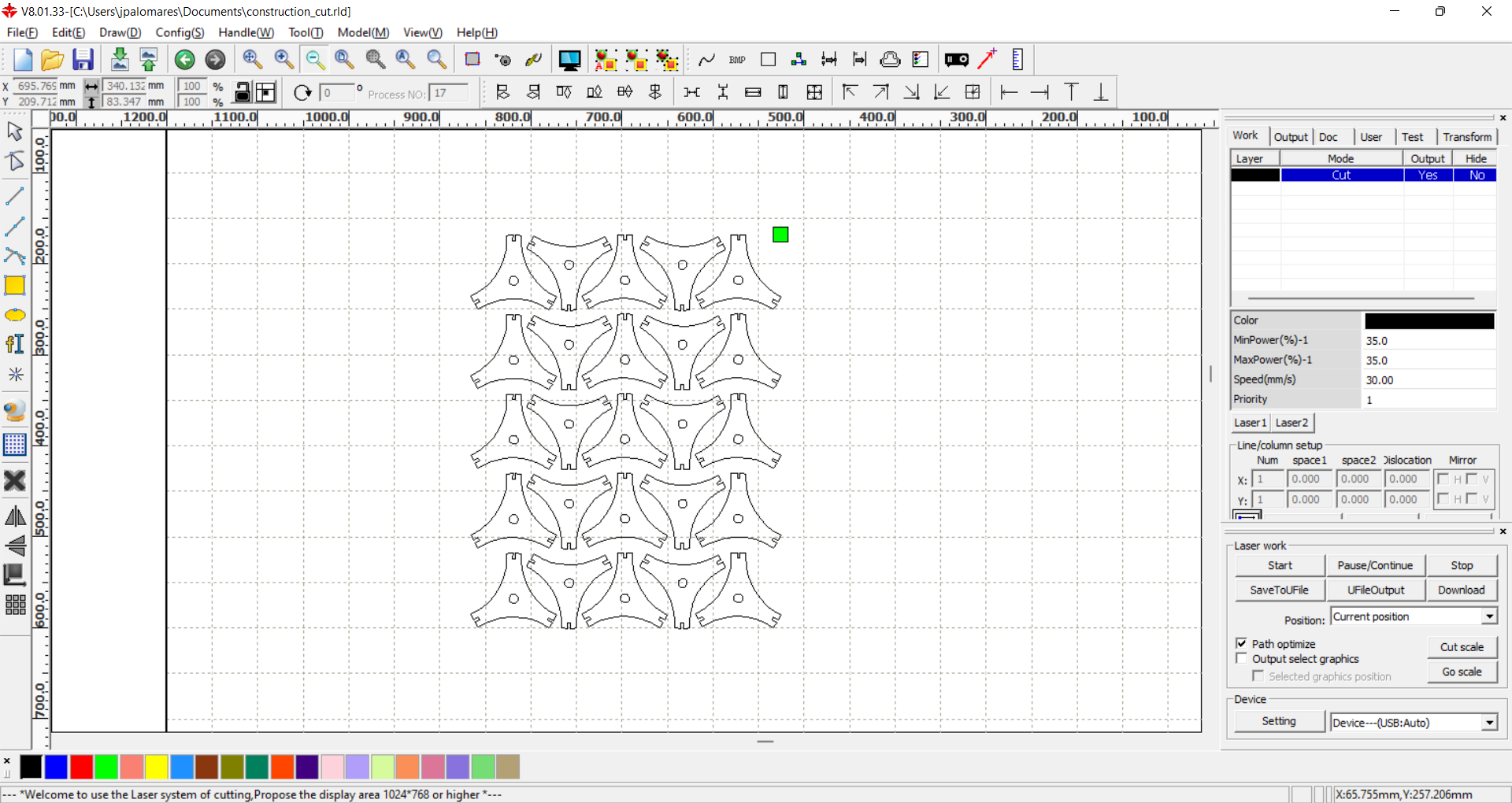
Then I proceed the cut
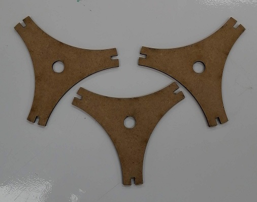
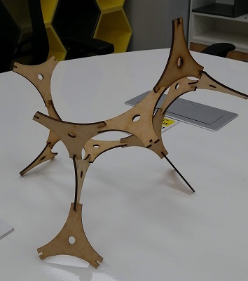
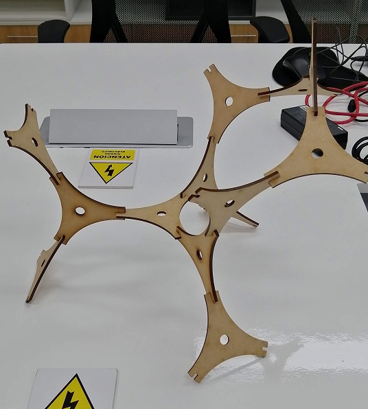
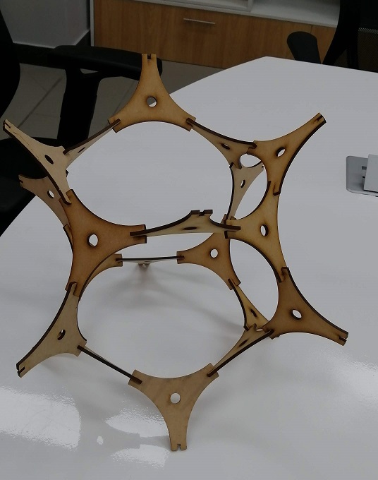
Then I assembled some structures!
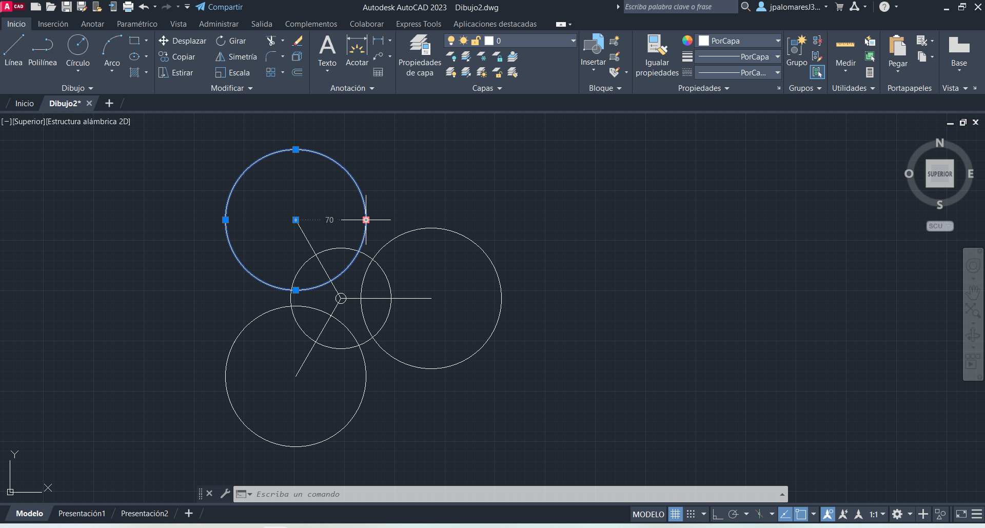
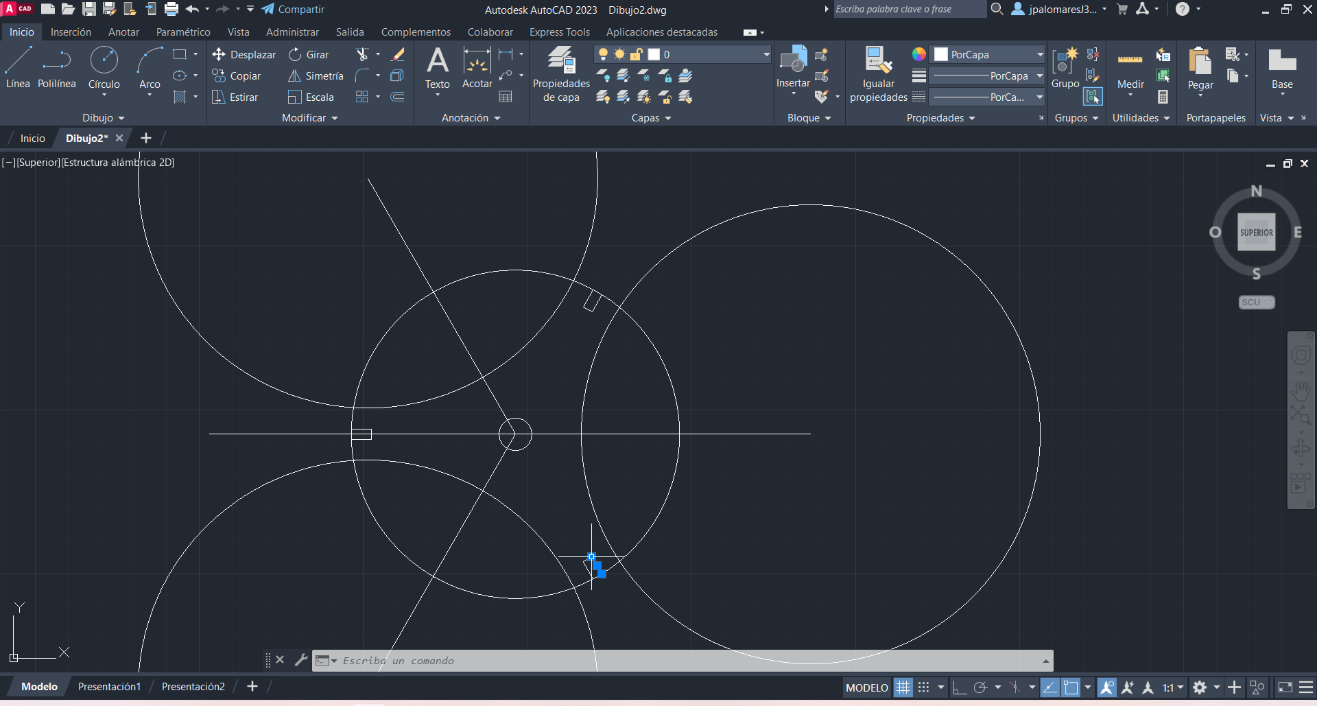
Parametric design in AutoCAD:
I decided to edit my box with parametric settings, with the purpose of use it with diferents depths. Template plans obtained from makercase.com, exported in DXF format.
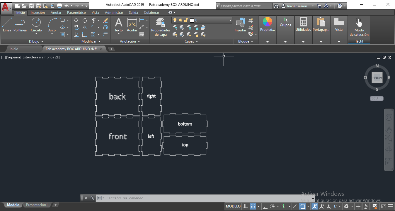
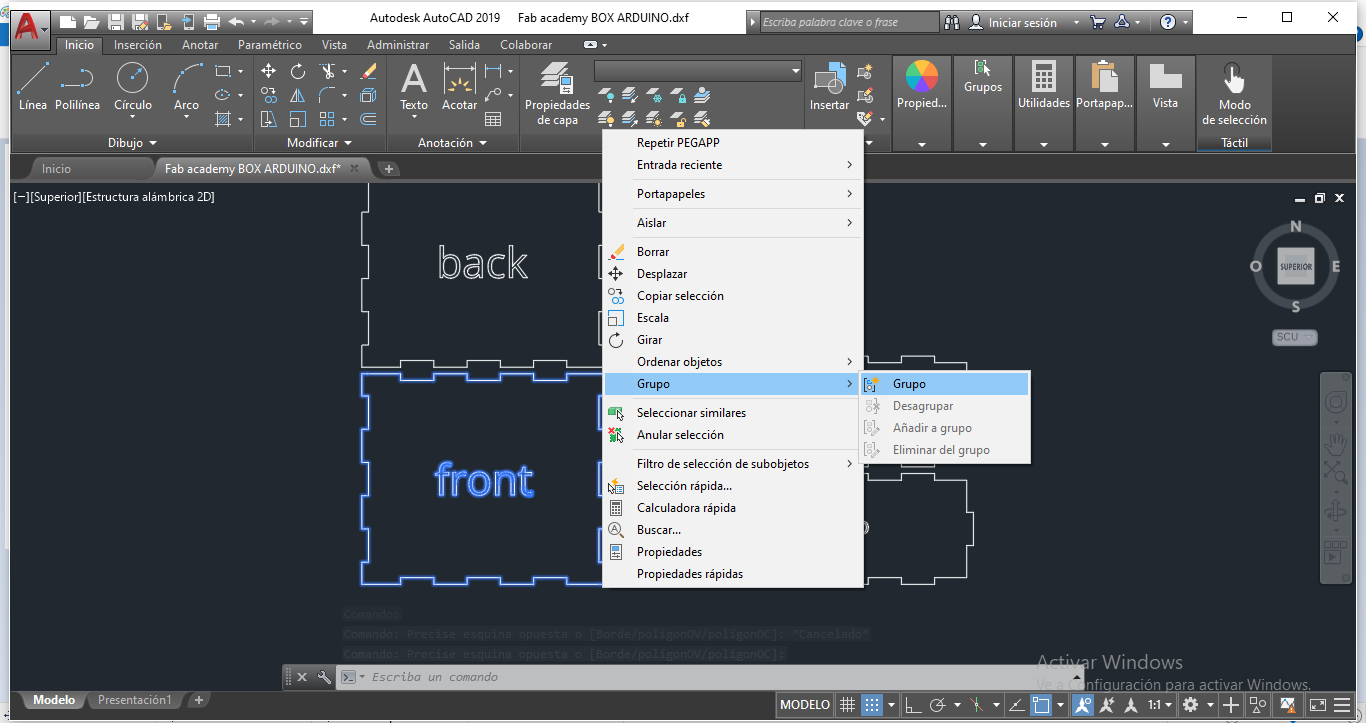
STEP 1:
First, I select the Front part and I group lines.
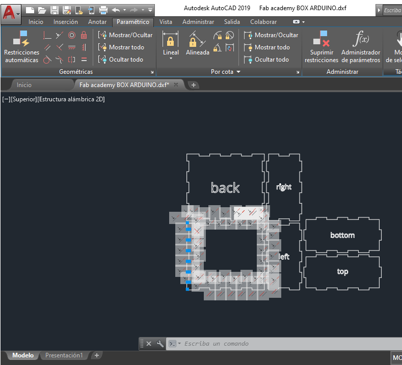
STEP 2:
Next, with front panel selected, choose Parametric Menu, and select Automatic Restrictions. We'll see every line with some options. The goal is parametrize the depth of junctions in all parts of the box.
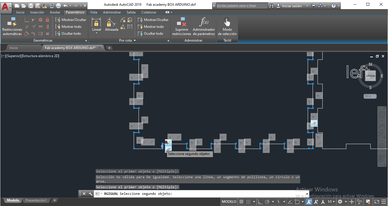
STEP 3:
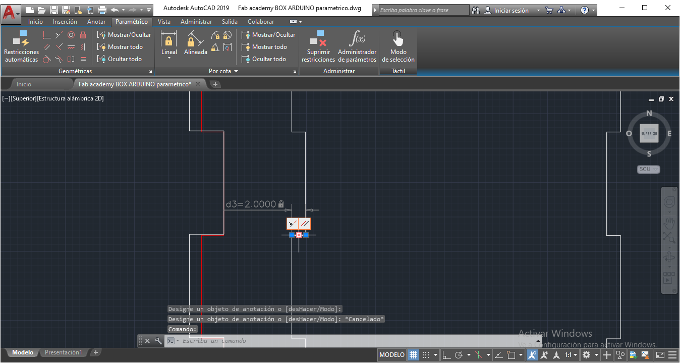
Choose Equal Restriction from the parametric toolbar and select the depth line from the bottom part, then the depth line from de left part. We'll se an equivalency when I we tried to stretch
STEP 4:
Repeat the process with the other parts (right and up).
STEP 5:
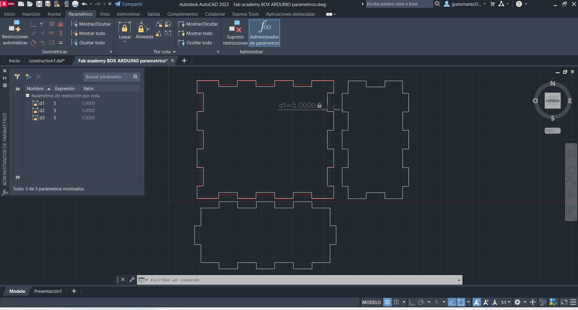
Measure the line with equal resctriction. It can be modified to other value, and we'll see all the parts are equal. In this case, it was tested with 5 mm.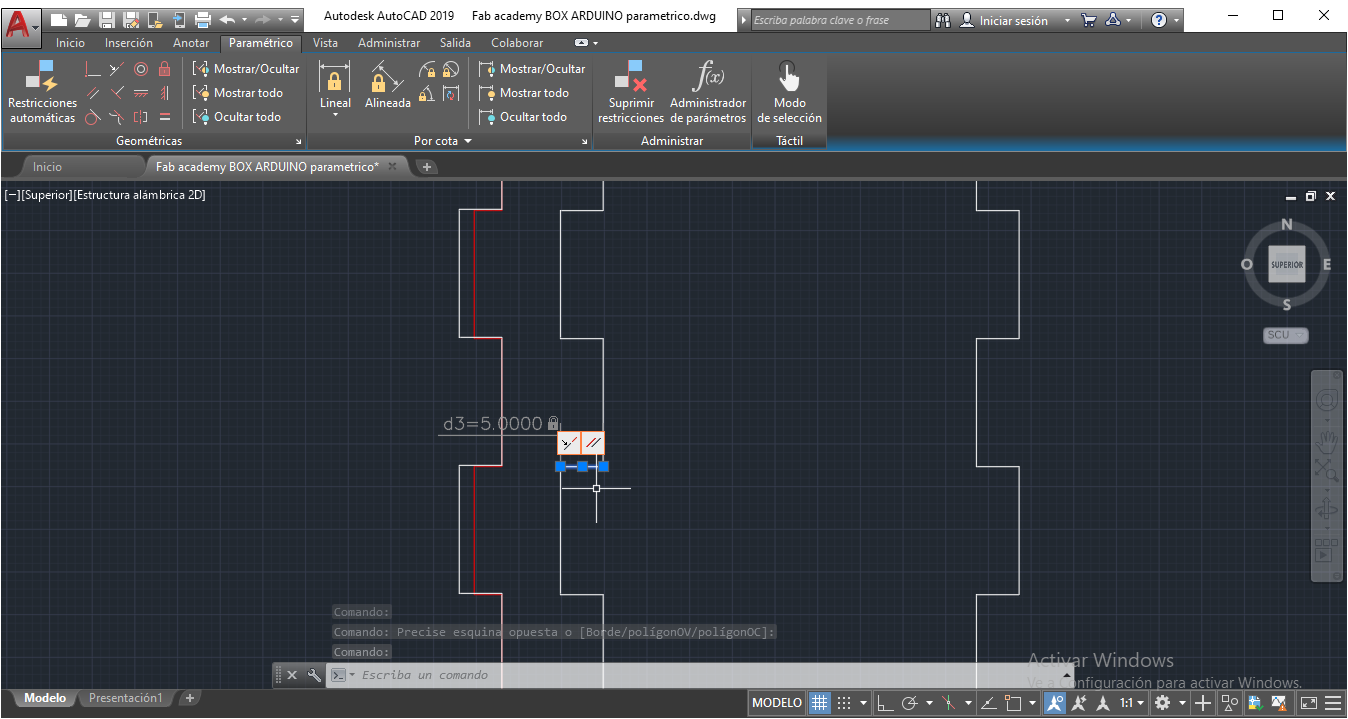
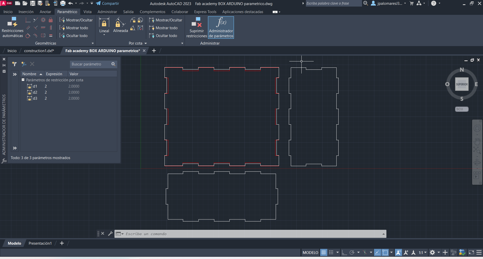
Then, it was tested with 2mm
To change depth values, Go to Parametrics menu, Parametrics administrator. Then, change d1,d2 and d3 values according material depth.
for 5 mm:
for 2mm:
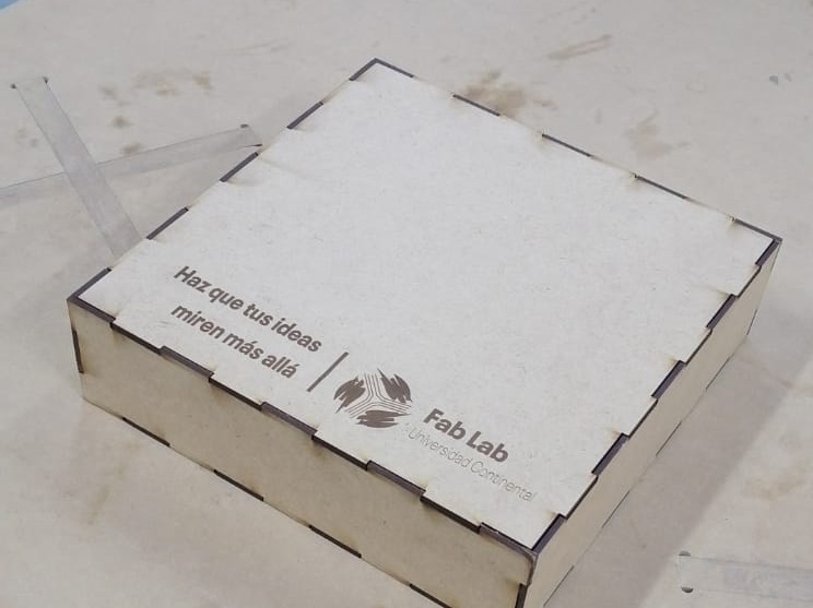
Pressfit Kit Design:
After the parametric design in AutoCAD, I made a pressfit box using the laser cutting machine.
The material for test was MDF, 3mm of depth.
Cut parameters: Speed: 25mm/s Power: 70%
Engraving parameters: Speed: 100mm/s Power: 20%
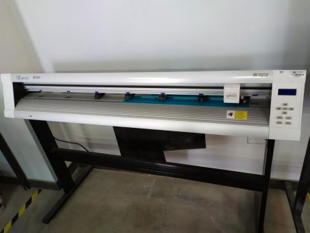
Vinyl Cutting:
Vinyl Cutter Specs:
Brand: MyCut
Model: MG1200
Voltage: 110V / 220V
Cache capacity: 256MB
Paper feed width: 1400mm
Cutter pressure: 0-600g / 1200g
Cutting width: 630 / 590mm
Cutting speed: 0-800mm/s
Driver: High Stepper Motor
Cutting length: Max 20000mm <=>
Repeated cut: 0-500 times
Size: 1670*320*390mm
Interface: USB / Serial Port / U-Disc Port / Network (WIFI optional)
Keywords: Vinyl cutting machine.
Large screen: easier operation.
Software: Coreldraw, Signmaster
Usage: Cut vinyl decal, heat press film
Item: Automatic Contour Cutting Plotter
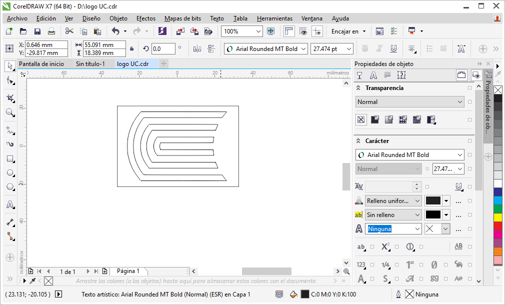
Corel Draw software was used to design and cut the Continental University logo for branding the final project.
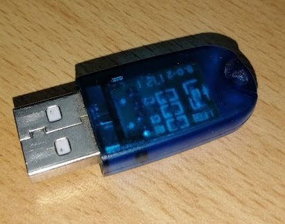
I used a plugin CutToolCDR to generate the G-code. So, I needed to insert a USB key for licensing.
Then, I selected the plugin CutToolCDR.
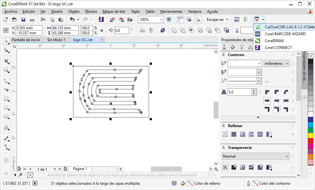
First I selected alI the design and chose the Cut/Plot option.
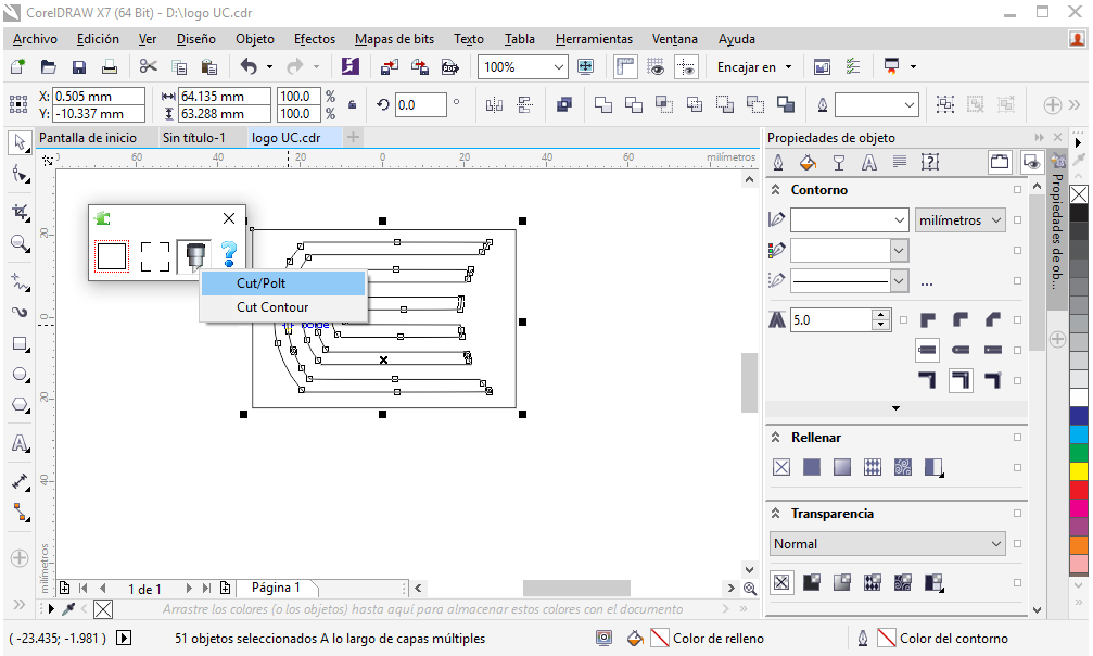
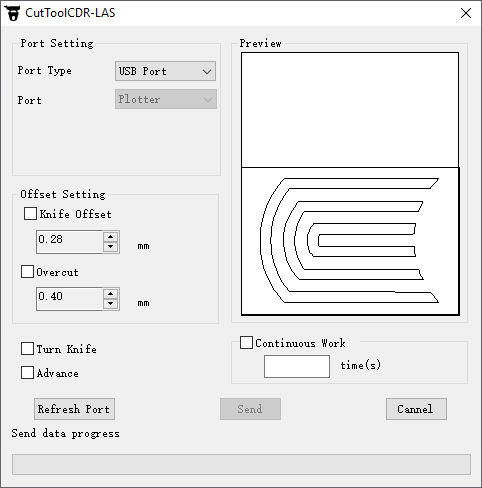
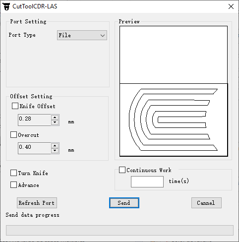
in the CutToolCDR plugin I saw some options:
Port type: USB Port, for connecting and controlling the vinyl plotter directly to PC through USB port.
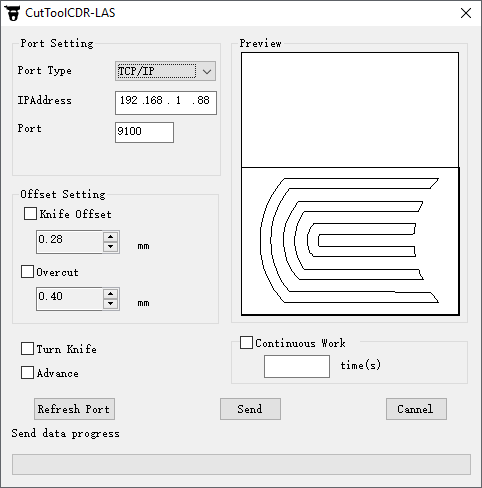
Port type: TCP/IP, for connecting and controlling the vinyl plotter through a Ethernet connection.
We can see other two parameters in Offset Setting
Knife Offset: Offset is the measurement that determines the blade’s turning radius and compensation for distance while turning corners.
Overcut: The overcut setting is used to tell the machine to cut a little further at the end of a shape to help guarantee closure. This is due to the fact that the blade tip is positioned at an angle and not directly in the center of the holder. The overcut amount set will indicate how much it should continue to cut past the end of the path.
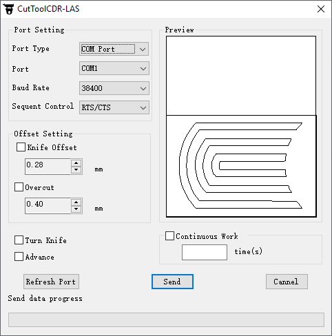
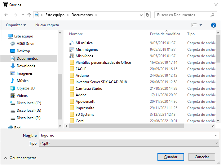
To generate the G-code I changed port type to FILE, next Send button to save the file.
I saved the plt file to a USB Stick.
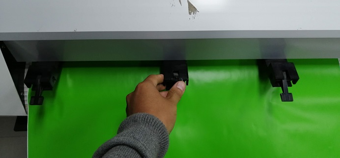
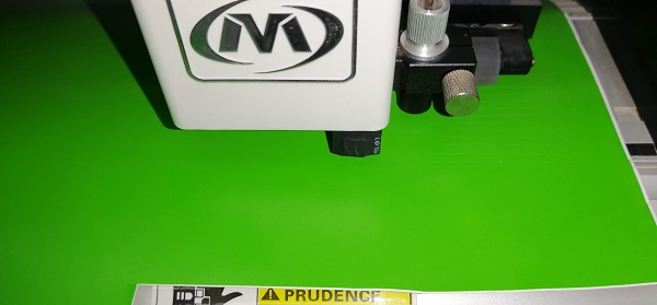
Next, I prepared the vinyl plotter, first I adjusted the green vinyl.
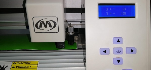
Then turned on the vinyl plotter. The speed and strength values are shown.
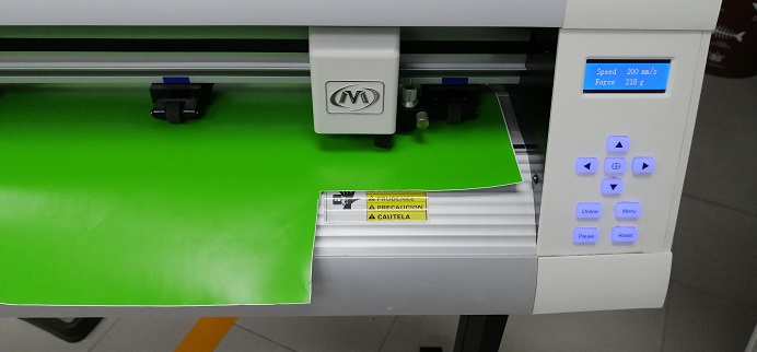
Next, I setted the origin point with the arrows. In this case X= -10 and Y= -435. Pushing middle button to accept.
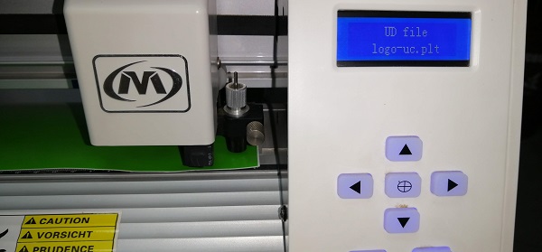
Then, I put the USB Stick on USB port of ninyl plotter, next I entered to Menu and selected the USB UD file, plt file. Pushing middle button to start cutting!
The cutting process was started.
After a couple of minutes, the cutting was finished.
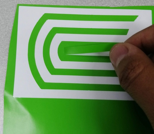
The unused vinyl was removed.
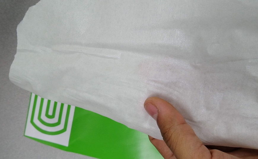
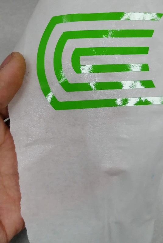
Then, I put transfer paper on top the vinyl.
I did some strengh over the transfer paper.
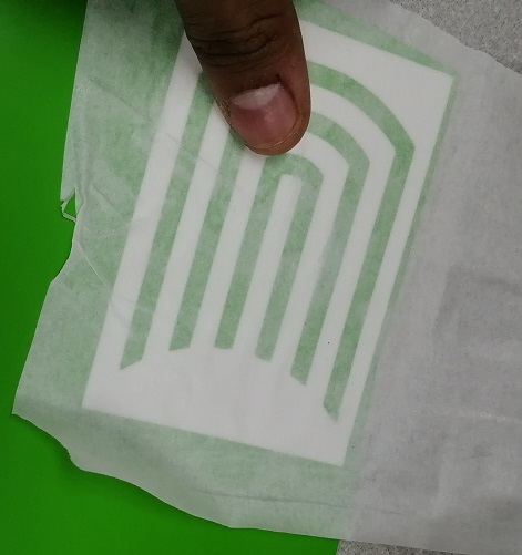
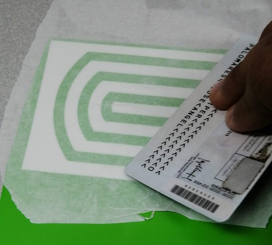
With the help of a plastic I put more pressure so that it sticks better.
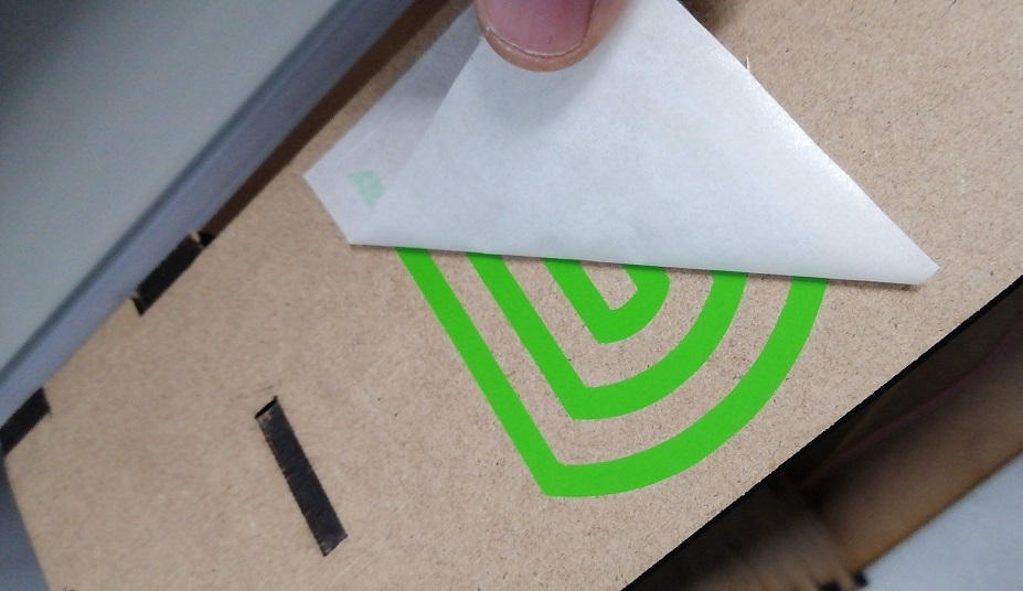
Then very carefully I released the transfer paper from the vinyl
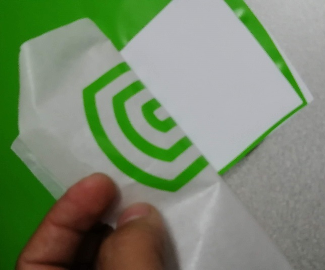
So, you can see that the vinyl was well attached to the transfer paper.
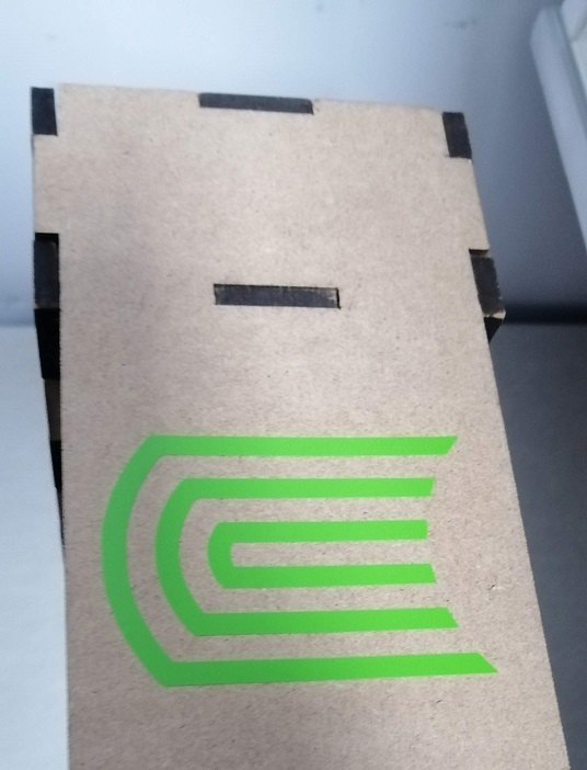
Next, I put the transfer paper over my estructure for branding.
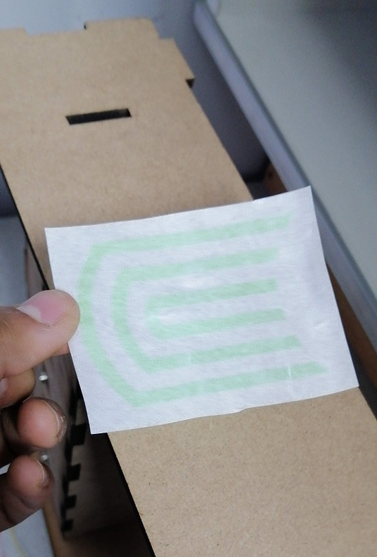
I did some preasure over the transfer paper to sticky.
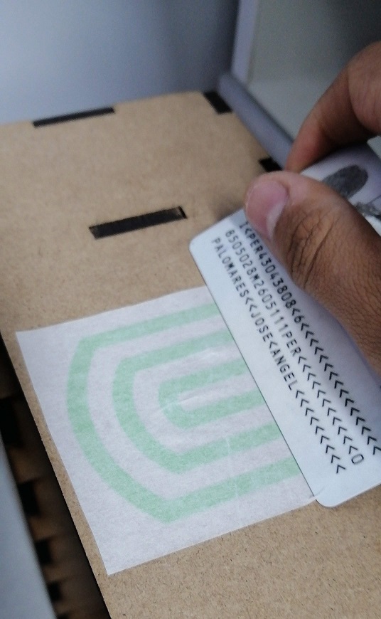
Next, I very carefully removed the transfer paper and noticed that it adhered correctly to the structure.
Finally view.
Download
The project files and plans are available here
Assignment Conclusions
- When designing, the precision of the laser cut is very important, as it must be matched so that it fits perfectly.
- The technique of parameterizing a design has many advantages, one of them is that it is not necessary to make a new design, but only to change parameters of length, width and thickness. With which we save a lot of time.
- When I made laser cuts in different materials, I realized that harder materials require more cutting power (MDF and acrylic) and less power for weaker ones like corrugated cardboard. It also has to do with the thickness of the material.
- Vinyl cutting was quite useful for labeling my final project. Vinyl cutting is done very quickly and the process to transfer the vinyl to the structure is simple and safe using transfer paper.
- This task was essential in the implementation of my final project since the power of the laser cutter must be configured correctly according to the material to make a fine cut and perfect fit.