Computer Design Aided
Logo Design
There are several software to design a logo:
Corel Draw:
CorelDRAW is a vector graphics editor developed and marketed by Alludo (formerly Corel Corporation). It is also the name of the Corel graphics suite, which includes the bitmap-image editor Corel Photo-Paint as well as other graphics-related programs (see below). It can serve as a digital painting platform, desktop publishing suite, and is commonly used for production art in signmaking, vinyl and laser cutting and engraving, print-on-demand and other industry processes. Reduced-feature Standard and Essentials versions are also offered.
This program requires a user license of $270.
Software link here

Inkscape:
Inkscape is a free and open-source vector graphics editor for traditional Unix-compatible systems such as GNU/Linux, BSD derivatives and Illumos, as well as Windows and macOS. It offers a rich set of features and is widely used for both artistic and technical illustrations such as cartoons, clip art, logos, typography, diagramming and flowcharting. It uses vector graphics to allow for sharp printouts and renderings at unlimited resolution and is not bound to a fixed number of pixels like raster graphics. Inkscape uses the standardized Scalable Vector Graphics (SVG) file format as its main format, which is supported by many other applications including web browsers. It can import and export various other file formats, including SVG, AI, EPS, PDF, PS and PNG.
Inkscape can render primitive vector shapes (e.g. rectangles, ellipses, polygons, arcs, spirals, stars and 3D boxes) and text. These objects may be filled with solid colors, patterns, radial or linear color gradients and their borders may be stroked, both with adjustable transparency. Embedding and optional tracing of raster graphics is also supported, enabling the editor to create vector graphics from photos and other raster sources. Created shapes can be further manipulated with transformations, such as moving, rotating, scaling and skewing.
This software is an open source solution. That's why I chose this option
Software link here

My logo was designed in the Inkscape software, that is free and open source vector graphics editor.
I used a logo from ETABLISSEMENTS MAZEAU S.A, (https://www.mazeau.fr/public/15-15-en.html) France.
![]()
Some basic concepts:
RASTER:
Raster files are images built from pixels — tiny colour squares that, in great quantity, can form highly detailed images such as photographs. The more pixels an image has, the higher quality it will be, and vice versa. The number of pixels in an image depends on the file type (for example, JPEG, GIF, or PNG).
VECTOR:
Vector files use mathematical equations, lines and curves with fixed points on a grid to produce an image. There are no pixels in a vector file. A vector file’s mathematical formulas capture shape, border, and fill colour to build an image. Because the mathematical formula recalibrates to any size, you can scale a vector image up or down without affecting its quality.
There are several programs that perform this function, like Corel Draw, Inkscape, Adobe Illustrator, etc. I choose Inkscape because it's free and simple to use.
RENDER:
The Render is a digital image that is created from a 3D model or scenario made in a specialized computer program, whose objective is to give a REALISTIC appearance from any perspective of the model.
STEP 1:
Next, download and install Inkscape, then open a new document.

STEP 2:
Open the image tu use into inkscape.
![]()
STEP 3:
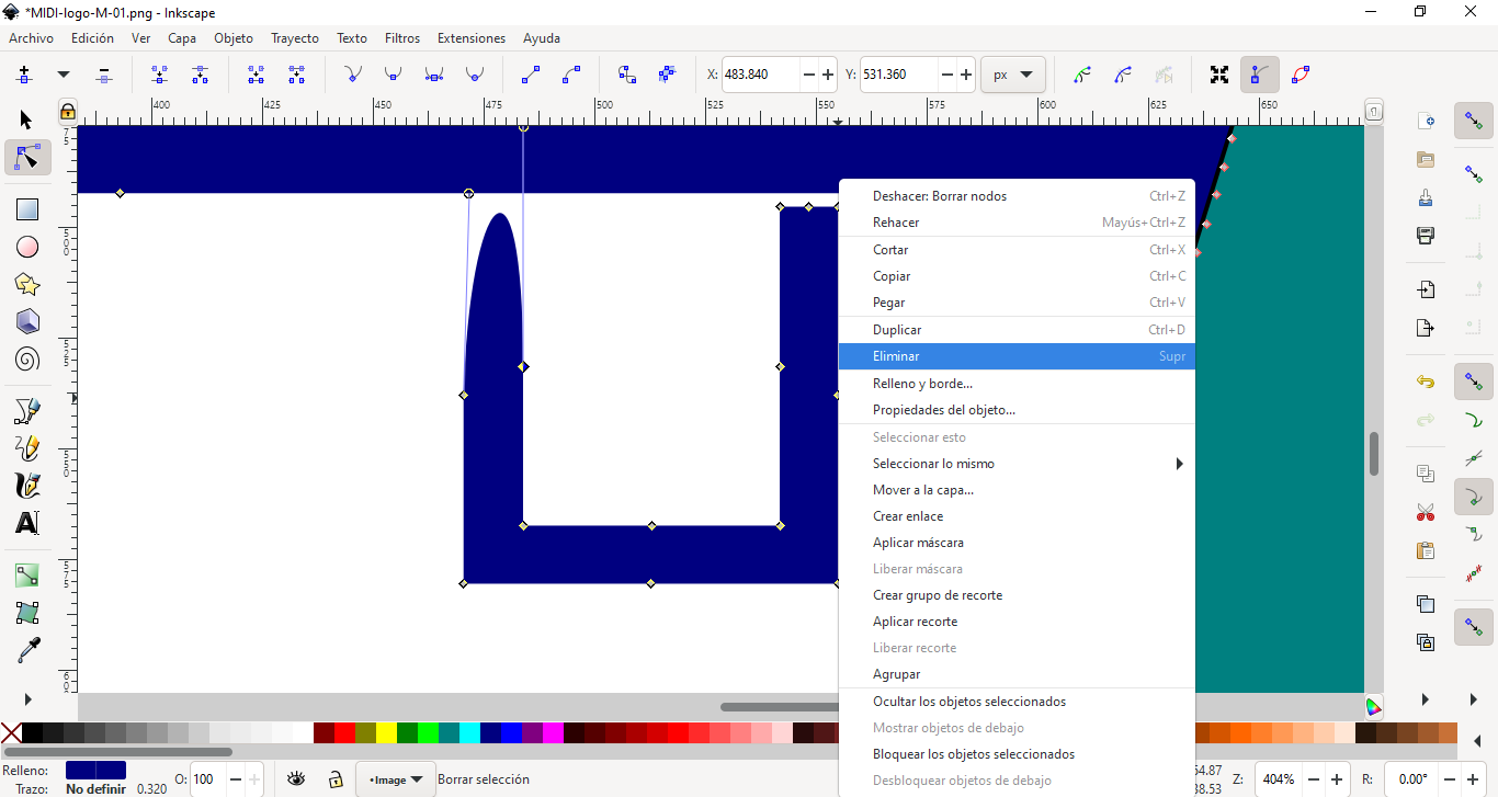
Next, vectorize image. Select option from menu. (right click on the image)
![]()
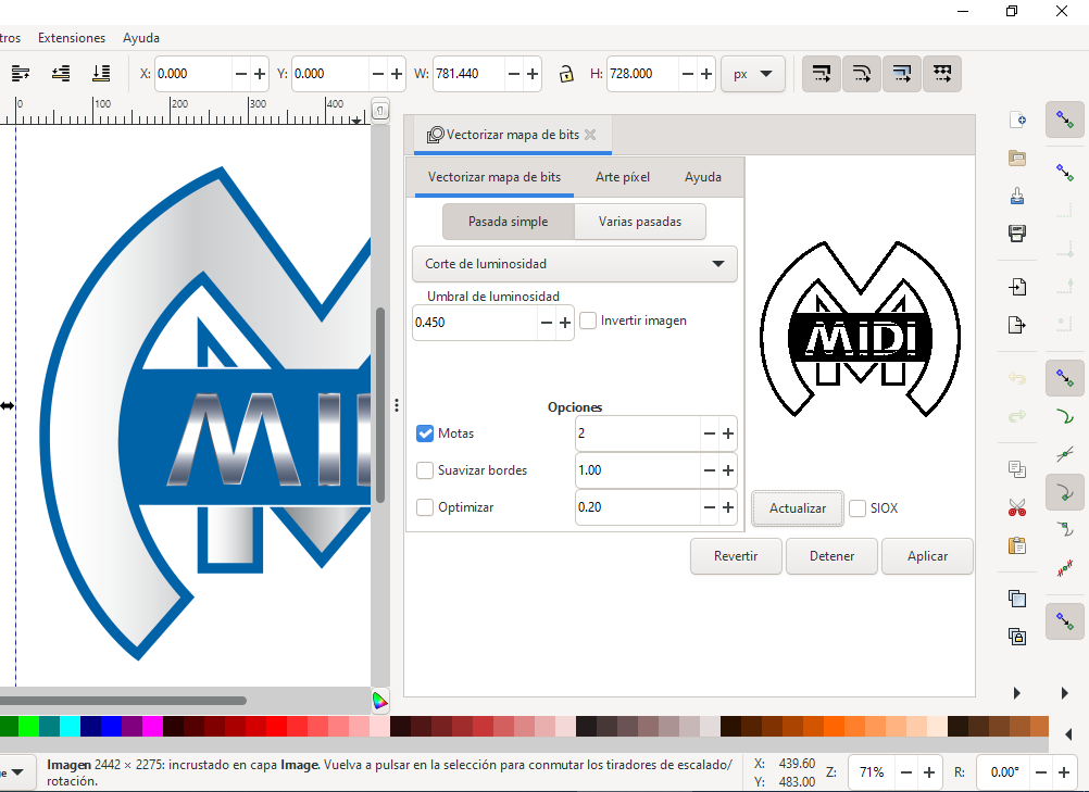
STEP 4:
Configure vectorize options for best results. In this case uncheck smooth borders and optimize. Then Apply.
STEP 5:
When vectorized, delete the old image (non vectorized) and select the vectorized image. Proceed to edit nodes to improve the image.

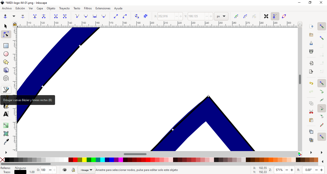
STEP 6:
Select Bezier tool to draw a fill of the image.
STEP 7:
Next, choose a color of the fill
STEP 8:
Then, I remove some nodes to add a block below the MIDI box.
STEP 9:
A text block was added, but set to background (Object Menu - set to back)

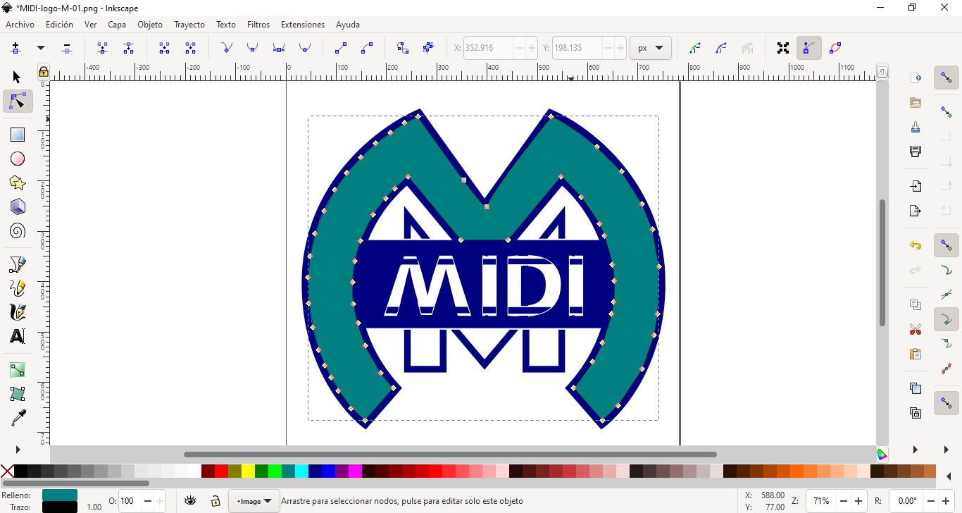
STEP 10:
Next, Change the text box and add some text, the text color was changed too.
![]()
STEP 11:
Finally, the image was exported in PNG format.
![]()
Conclusion
Finally, I think Inkscape is an easy tool to make this kind of logos for my projects. It's free (open source) and has a big community of users in the world.
I'm planning to put this logo on my final project, maybe using a vinyl plotter for cutting.
2D MODELLING
There are several software for 2D design:
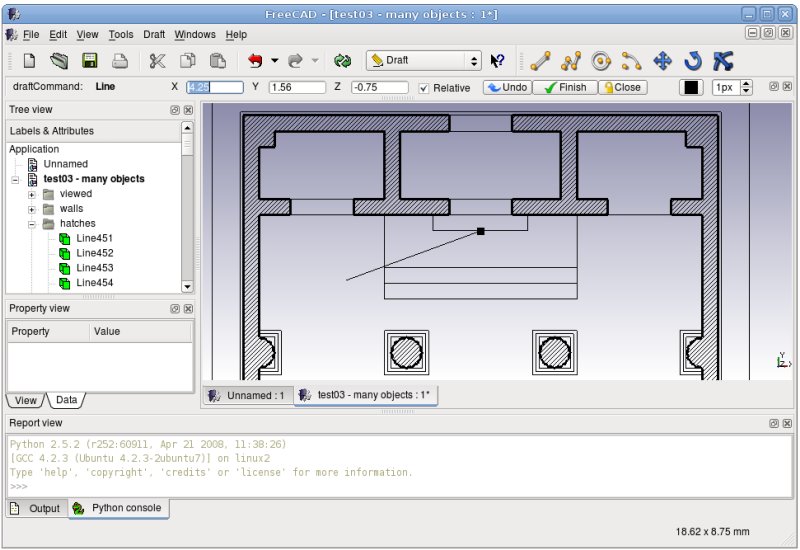
FreeCAD:
FreeCAD is a general-purpose parametric 3D computer-aided design (CAD) modeler and a building information modeling (BIM) software application with finite element method (FEM) support.[2] It is intended for mechanical engineering product design but also expands to a wider range of uses around engineering, such as architecture or electrical engineering. FreeCAD is free and open-source, under the LGPL-2.0-or-later license, and available for Linux, macOS, and Windows operating systems. Users can extend the functionality of the software using the Python programming language.
FreeCAD is an open source solution. But, I am not very used to using this program.
Software link here
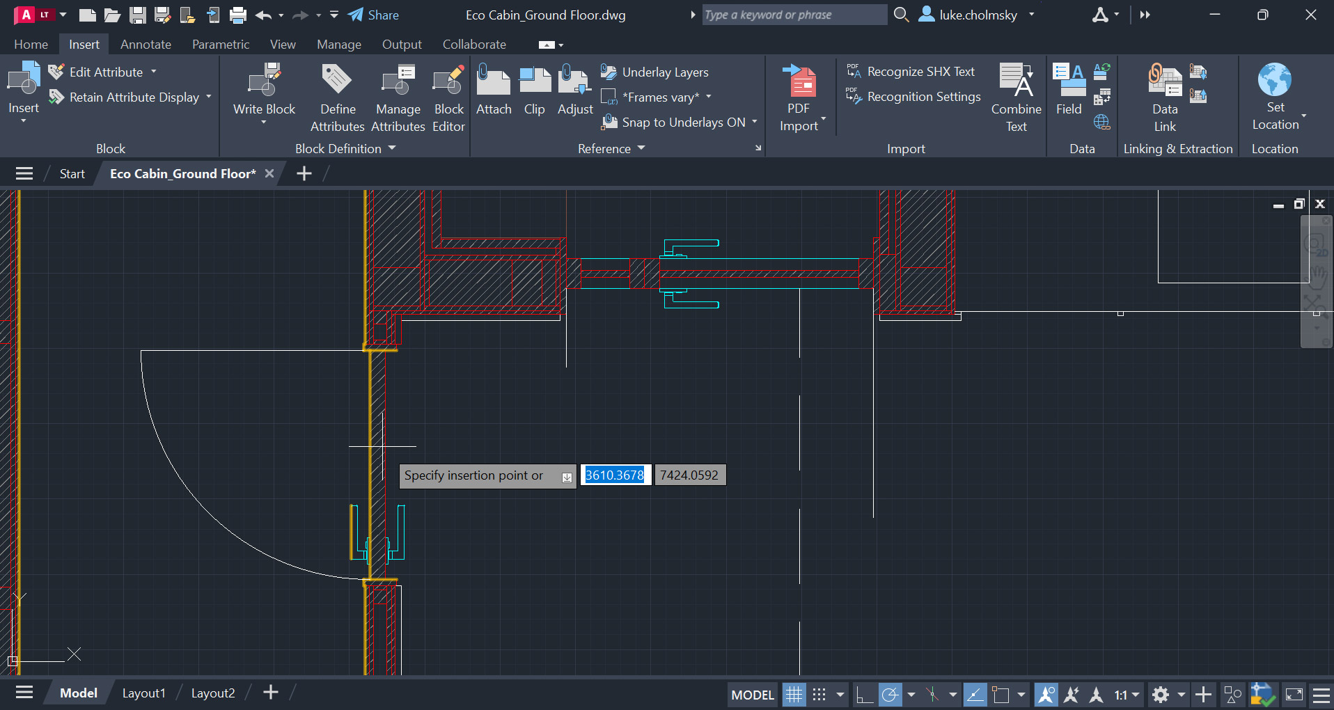
AutoCAD:
AutoCAD is a 2D and 3D computer-aided design (CAD) software application developed by Autodesk. It was first released in December 1982 for the CP/M and IBM PC platforms as a desktop app running on microcomputers with internal graphics controllers. Initially a DOS application, subsequent versions were later released for other platforms including Classic Mac OS (1989), Microsoft Windows (1993) and macOS (2010), along with companion web and mobile applications.
AutoCAD is a general drafting and design application used in industry by architects, project managers, engineers, graphic designers, city planners and other professionals to prepare technical drawings. After discontinuing the sale of perpetual licenses in January 2016, commercial versions of AutoCAD are licensed through a term-based subscription.
The university where I belong provides us with educational licenses, therefore, I have chosen to use this program under that modality. I am also quite used to this software.
Software link here
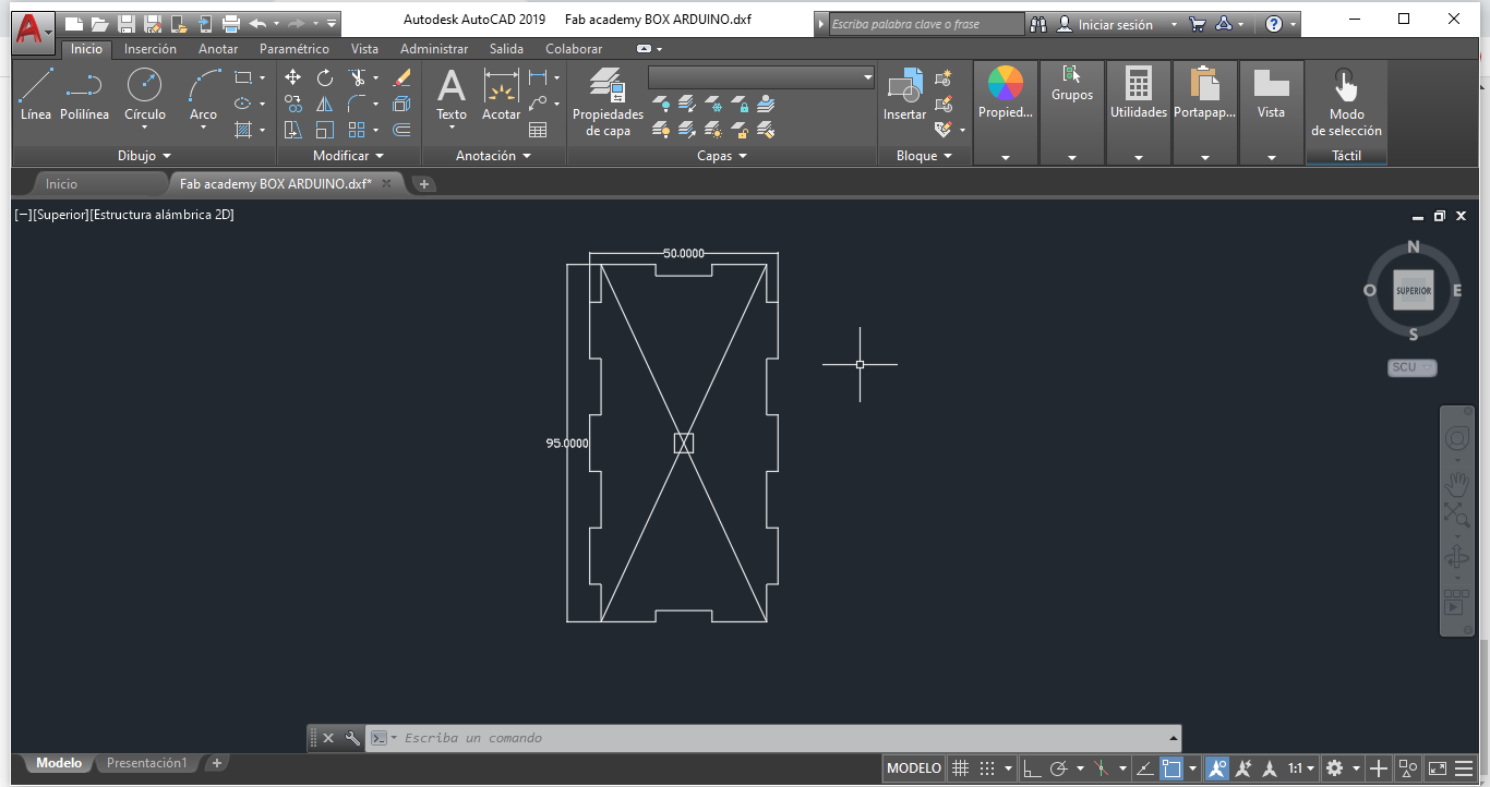
My project needs a box to support and protect my control circuit. I decided to make a custom box in MDF. I used the software AutoCAD to design it.

STEP 1:
The box will have a 110 (length) x 95 (width) x 50 (height) centimeters. Default units (mm) was used. It will has 2 holes, to pass the cables and power supply.

STEP 2:
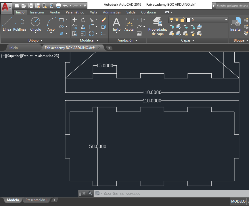
First, the box will has 3 joints per side for the cover and back; and 1 in the other sides. The joint will has a 15 mm of size. THe depth of the MDF is 3mm.


STEP 3:
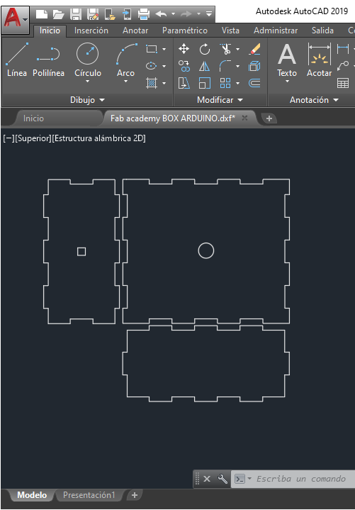
Complete the top side and make a circle in the center.
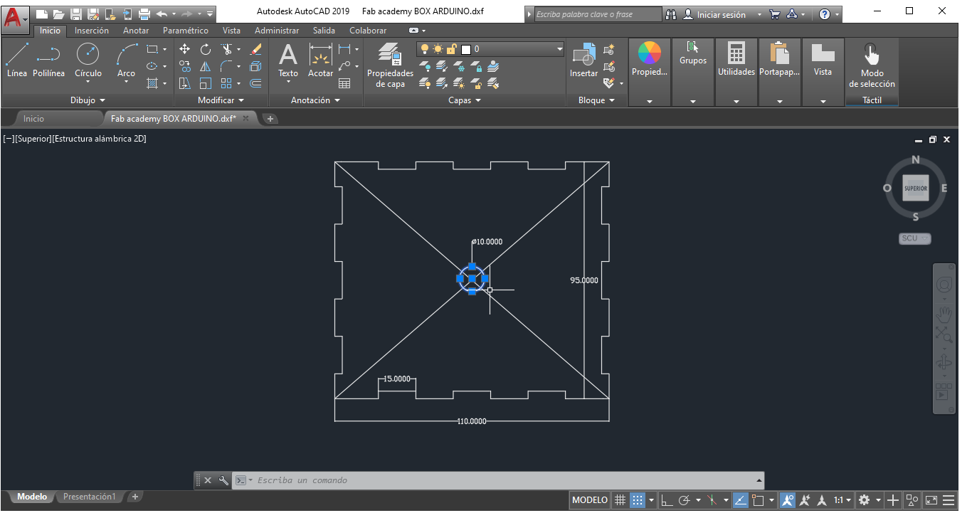
STEP 4:
Next, draw the left side, a square in the center.
STEP 5:
Draw the last part of the box, bottom part.
STEP 6:
Finally duplicate the designs to assemble the box. Use copy tool.
STEP 7:
My logo was added to the top side of the box.
![]()
My proposed structure for my final project is as follows.

Make a structure design of MDF material 53,1 cm high, 30 cm wide and 11 cm deep.
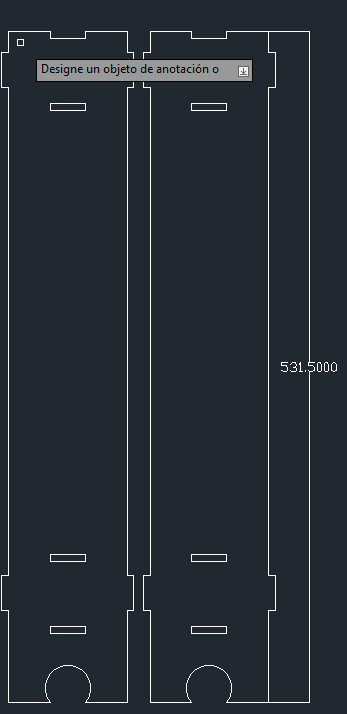
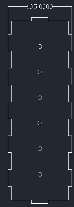

Drilled 6 holes in the base in order to place the laser modules emitters. The diameter is 6.5mm to match laser module diameter.

Then, 2 holes were made to place the LDR receiving light sensors. Its diameter is 1 mm.

Finally, leave a rectangle to pull out the USB cable from the controller to the PC. The measurements were 10cm x 12cm.

Conclusion:
This time I used Autocad software because I know this application since many years ago and it's easy for me to make a quick design of a box. I'm planning to use this box for support my electronic controller of my final project.
Files:
3D MODELLING
There are several software for 3D design:
Rhinoceros 3D:
Rhinoceros (typically abbreviated Rhino or Rhino3D) is a commercial 3D computer graphics and computer-aided design (CAD) application software that was developed by TLM, Inc, dba Robert McNeel & Associates, an American, privately held, and employee-owned company that was founded in 1978. Rhinoceros geometry is based on the NURBS mathematical model, which focuses on producing mathematically precise representation of curves and freeform surfaces in computer graphics (as opposed to polygon mesh-based applications).
Rhinoceros is used for computer-aided design (CAD), computer-aided manufacturing (CAM), rapid prototyping, 3D printing and reverse engineering in industries including architecture, industrial design (e.g. automotive design, watercraft design), product design (e.g. jewelry design) as well as for multimedia and graphic design.
Rhinoceros is developed for the Microsoft Windows operating system and macOS. A visual scripting language add-on for Rhino, Grasshopper, is developed by Robert McNeel & Associates.
This program requires a user license of $995
Software link here
SolidWorks:
SolidWorks (stylized as SOLIDWORKS) is a brand within Dassault Systèmes that develops and markets solid modeling computer-aided design, computer-aided engineering, 3D CAD design and collaboration, analysis, and product data management software.
The SolidWorks brand was founded as Winchester Design Systems by Massachusetts Institute of Technology graduate Jon Hirschtick on December 30, 1993.
SolidWorks developed the world's first 3D CAD solution that ran on a desktop PC. They had a simple mission statement of "3D on every engineer's desktop".
SolidWorks released its first product, SolidWorks 95, on November 1, 1995. Within two months, it established a new benchmark for ease of use.Since then, the 3D CAD product, now known as SolidWorks, has become the flagship product for the SolidWorks brand.
The university where I belong provides us with educational licenses, therefore, I have chosen to use this program under that modality. I am also quite used to this software.
Software link here
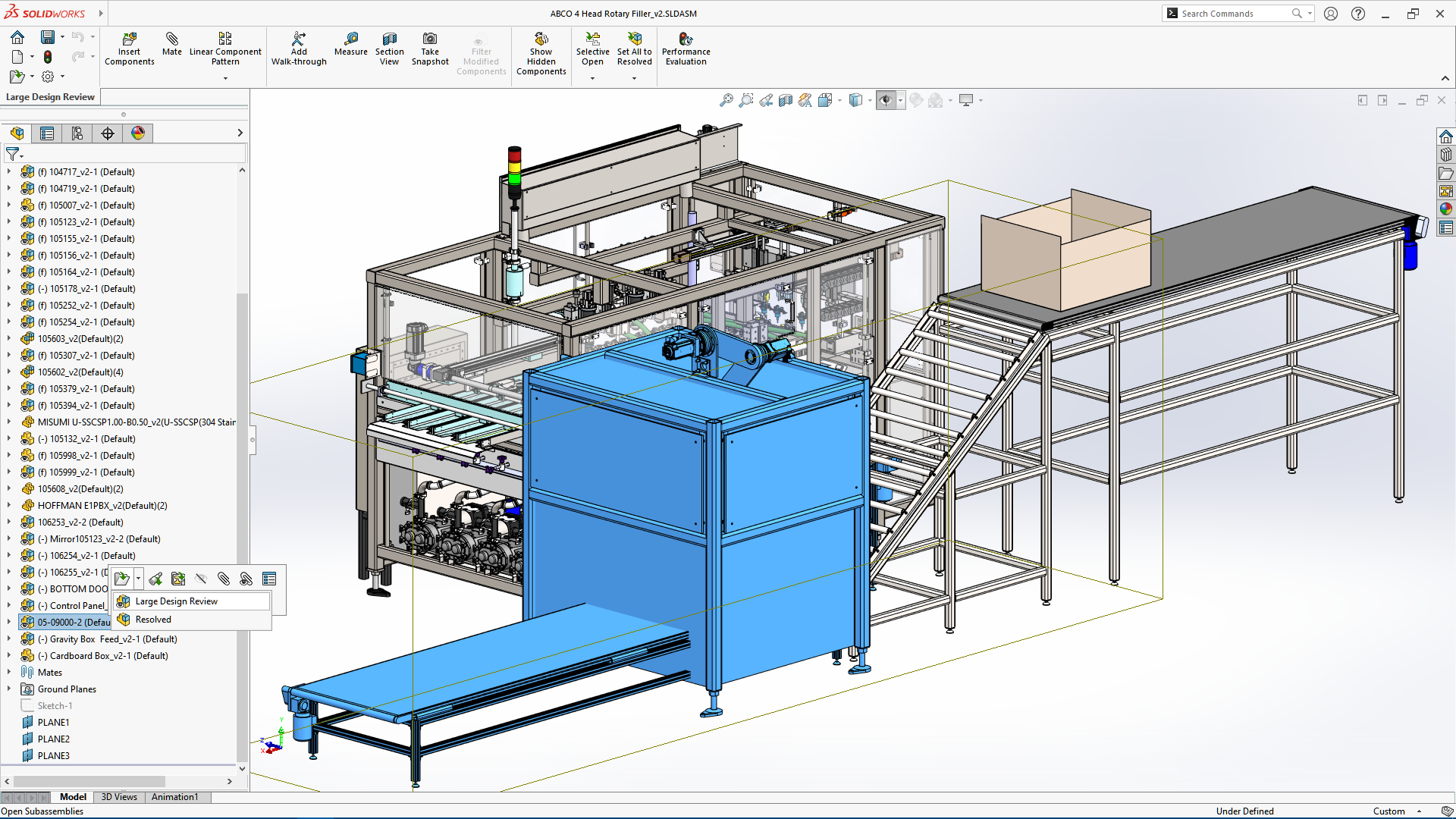
STEP 1:
This MIDI controller needs a support to work on. A structure was designed in SoldWorks software.
SolidWorks:
SolidWorks is a solid modeling computer-aided design (CAD) and computer-aided engineering (CAE) application published by Dassault Systèmes.
STEP 2:
Following the paper sketch, we build a new project, then draw the base and columns of the structure. Basiically a rectangle and lines were inserted. Then, a extrusion was applied.

STEP 3:
Next, the supports of lasers were inserted above the base.

STEP 4:
Next, the strcuture was completed with the correct measures .

STEP 5:
Next, a hole was inserted on the laser supports, then repeat the same step to complete for 12 holes.


STEP 6:
Finally, the structure design was finished.

ANIMATION:
A animation of assembly of the structure was done on the same software.
STEP 1:
First, every part of the strecture was show in the assembly workarea.

STEP 2:
Next, Go to Motion Study, on the bottom part.

STEP 3:
Each part has a timeline to control the motion. Initial state and final state.

STEP 4:
Next, Set the frame with the part to match with the next one.
To add a rorating model, go to Animation Wizard option, then configure the axis rotation,number of rotations and time.

STEP 5:
A several frames were added to the timeline.
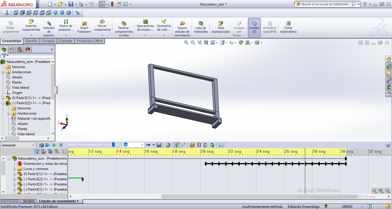
STEP 6:
THe assembly was finished, go to Save option to export in AVI format.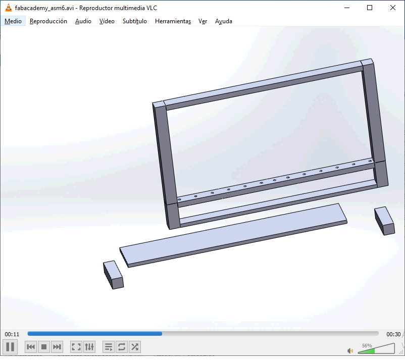
Conclusion
I think that having a 3D view of the final project is a great idea to have a better view. Autodesk Inventor and Solidworks are good choices for this.
This time I used Solidworks, because my Fab Lab has this software with a lot of tutorials. I found this software its not too difficult to learn, then I decided to build the structure for supporting lasers of my final project.
Then I made an animation to assemble that structure.
I would like to learn how to use this software with CAM process, to make the milling.
Download
The project files and plans are available here
Rendered assembly video here