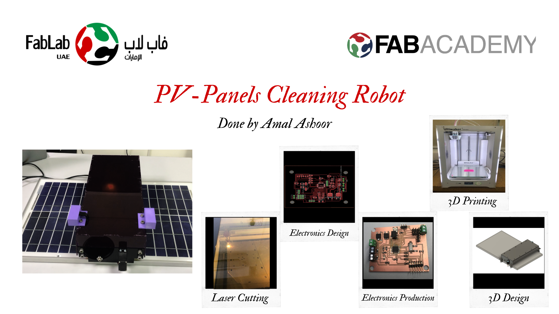
PV Panels Cleaning Robot
Idea : As a renewable energy engineer, I believe that one of the numerous issues facing PV systems is the accumulation of dust and dirt that reduce the photovoltaic (PV) efficiency. Thus, my final project is to create a solar panel cleaning robot by microfiber brush, instead of water, aiming to introducing a cost-effective cleaning system. This robot can be benefial in countries with similar climate as the UAE. The UAE's extremely arid landscapes make water scarcity a crucial issue.
Working Principle : This cleaning robot reads the time using an RTC. When the time is 4:30 AM, the continuous rotation servo motors start to move the robot using the ATmega328 board and the Lipo battery. The direction in which the robot moves depend purly in the signal recived from the ultrasonic sensor installed in the sides of the robot. These ultrasonic sensors help the robot to stop at the edges of the panel to aviod falling. During the movement of the robot, the brushes rotate since each microfiber brush is connected to a motor's rotor.
Questions to Answer
What does it do?
My final project is to create a solar panel cleaning robot. This robot depends on two rotating microfiber brushes to clean the panels without scratching their surface. These brushes are connected to 3D-printed tires and two continuous rotation servo motors. Thus, the robot will move along the solar panel while the cleaing process is taking place. Also, I included an ultrasonic sensor and RTC as input devices to read the distance and time, respectively.
Who’s done what beforehand?
Commercially, the majority of PV-cleaning robots use water. Thus, I decided to use microfiber brushes instead. After conducting a research, I notice that there was one cleaning robot that was designed in Fabacademy. In 2018, Gaurav Wadhwa designed Omni bot as a multi-purpose cleaning robot. This robot can move in X-axis and Y-axis independently and simultaneously.
What did you design?
I started by designing the ATmega328 board in the Output Devices week using Eagle software and a CNC machine. This board will control two continuous rotation servo motors (output device), two types of input devices: a real-time clock (RTC), and an ultrasonic distance measuring sensor. Then, I designed the two side plates, the robot cover, and the electronics box to place the motors and the electronics, respectively. Moreover, I designed the wheels. These parts are designed using Fusion 360 software.
Where did they come from?
All the components I used in this project are existed in the FabLab UAE, except the microfiber brushes.I bought these brushes from a local supermarket.
What materials and components were used? and How much did they cost?
The materials that will be used in this final project are MDF wood, acrylic, aluminum profiles, PLA filament, TPE filament, and microfiber brushes. However, the main electrical components that will be used are Lipo battery, ATmega328 microcontroller, ultrasonic sensor, RTC, and continuous rotation servo motor. In total, the estimated cost of the project is 1,609 AED or 438 USD. The following table gives all details about the used components and their costs.
| Component | Quantity | Cost Per Quantity(AED) |
|---|---|---|
| Mircofiber Brush | 2 | 15 |
| Screws and Nuts | - | 15 |
| TPE Filament | 1 | 191 |
| PLA Filament | 1 | 155 |
| MDF Wood Sheet | 1 | 155 |
| 3mm Purple Acrylic | 1 | 382 |
| 3mm White Acrylic | 1 | 382 |
| Lipo Battery | 1 | 15 |
| 20x60 Aluminum Extrusion | 1 | 144 |
| Ultrasonic Sensor | 2 | 37 |
| RTC | 1 | 30 |
| Continuous Rotation Servo Motor | 2 | 18 |
What parts and systems were made?
The microcontroller PCB and the electronics system are fabricated in the beginning. After that, the robot body is built. The robot body includes aluminum profiles, two side plates, wheels, and the robot cover.
What processes were used?
1. For electronics, I used Eagle to design the ATmega328 board and the battery regulator board. Then, I used Flatcam to generate Gerber files and the SRM Roland milling machine to produce the boards. After that, I soldered the elctronics and programmed the boards using Arduino IDE.
2. I designed the full robot using Fusion360 software that includes two side plates, the robot cover, the wheels, and the electronics surface (where I placed the electronics).
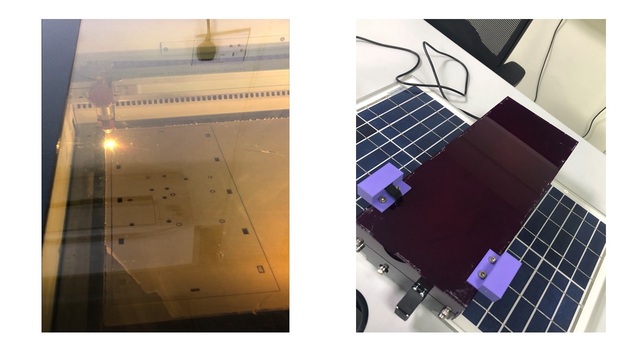
3. I used the speedy 400 flex laser cutter to create the two side plates, the robot cover, and and the electronics surface.
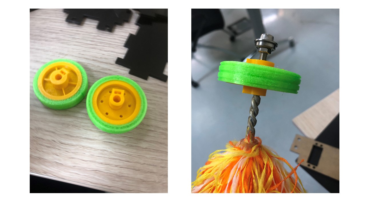
4. I 3D-printed the wheels using TPE and PLA filament.
What questions were answered?
1. How to control the robot and its sensors?
2. How to ensure that the robot will move in straight line?
3. What are the dimenions of the wheels?
What worked? What didn’t?
The working part are:
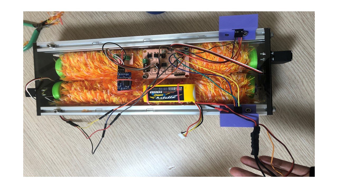
The solar-panels cleanign robot is able to clean surfaces from accumulated dust and dirt by microfiber brush. The main code of the ATmega328 and the battery regulator boards is working. Thus, the servo motors move after receiving signals from the real-time clock (RTC) and the ultrasonic sensors. Moreover, the robot moves in straight line and the brushes are rotating to clean the panels while this motion.
The not working part are:
Although the ultrasonic sensors are working individually and I was able to program them in the input week, they tend to deliever the signal slower to the microcontroller. As a result, I am thinking about designing a vertical stop parts attached to the panels and aline with these sensors.
How was it evaluated?
This project will succeed if two points are achieved. Firstly, if the robot is able to clean the panels effectively. Secondly, if the robot is controlled by the input devices.
What are the implications?
1. Try to create an interface between the robot and the phone to have full control on the robot.
2. Change the ultrasonic sensors position to vertical with 3D-printed parts attached to the PV to stop the robot from falling.
3. Experiment the cleaning impact of the robot with diffent percentage of dust accumulation.
4. Try to include compressed air duster in the robot to get better results.
Final Project Summary
1. Electronics
a. Designing:
During the Output Devices week, I designed an Ardiuno Uno-like board using ATmega328 microcontroller on Eagle software. This board can control output devices:two DC motors and two continous rotation servo motor, and input devices: a real-time clock (RTC) and two ultrasonic sensors.
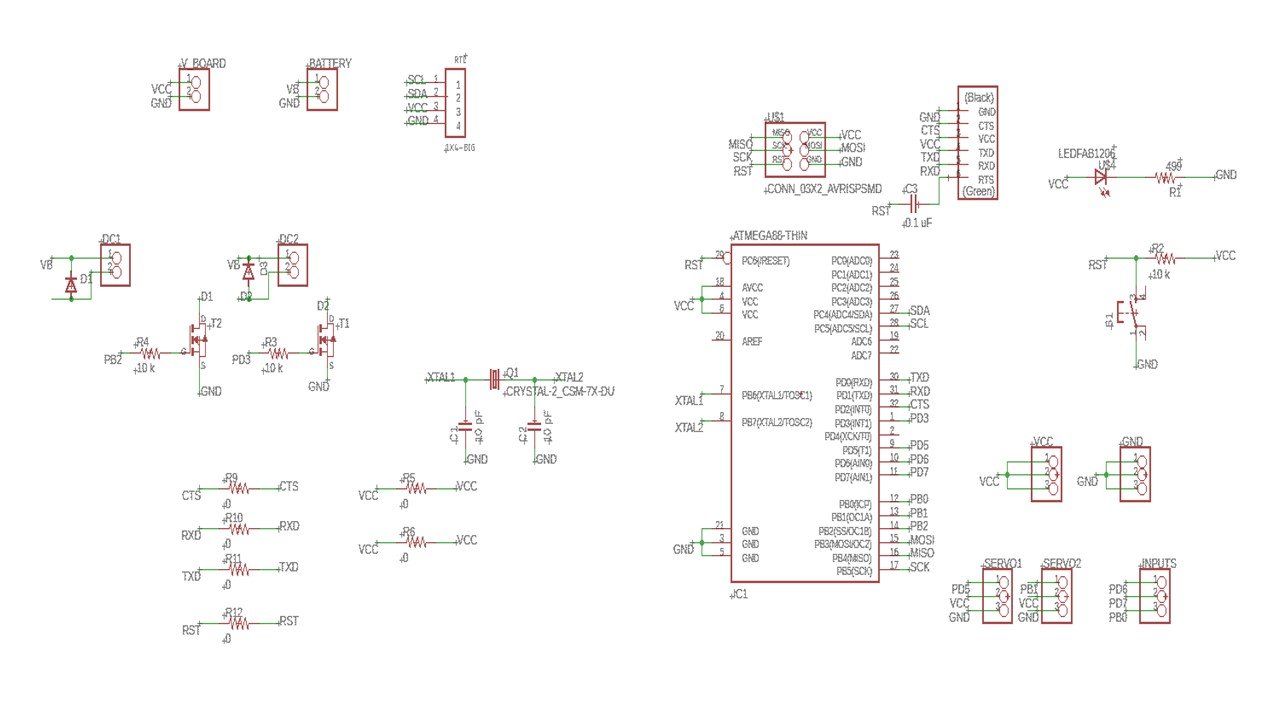
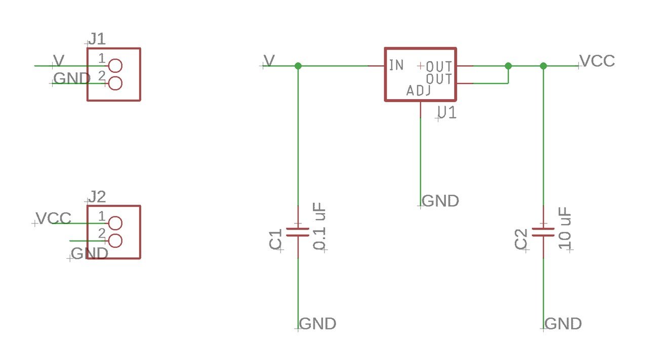
Then, I created another board to regulate the battery voltage using a regulator.
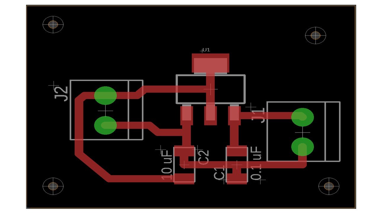
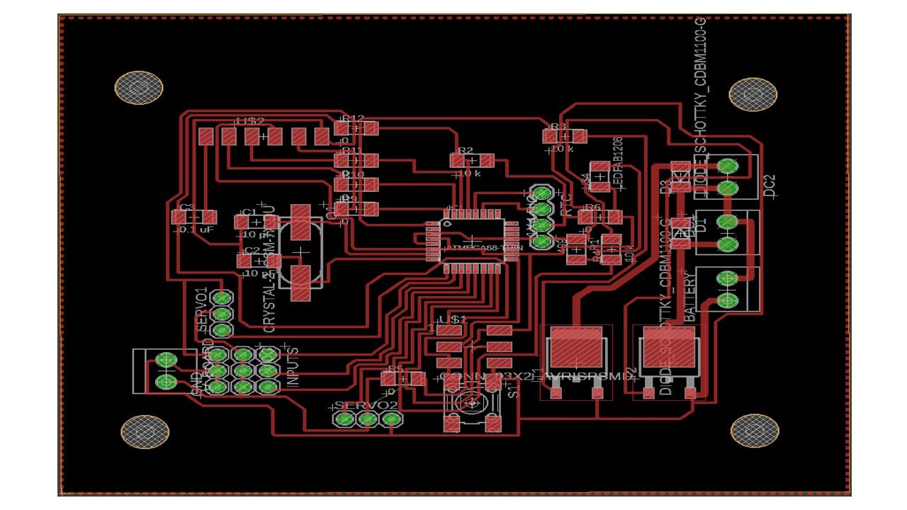
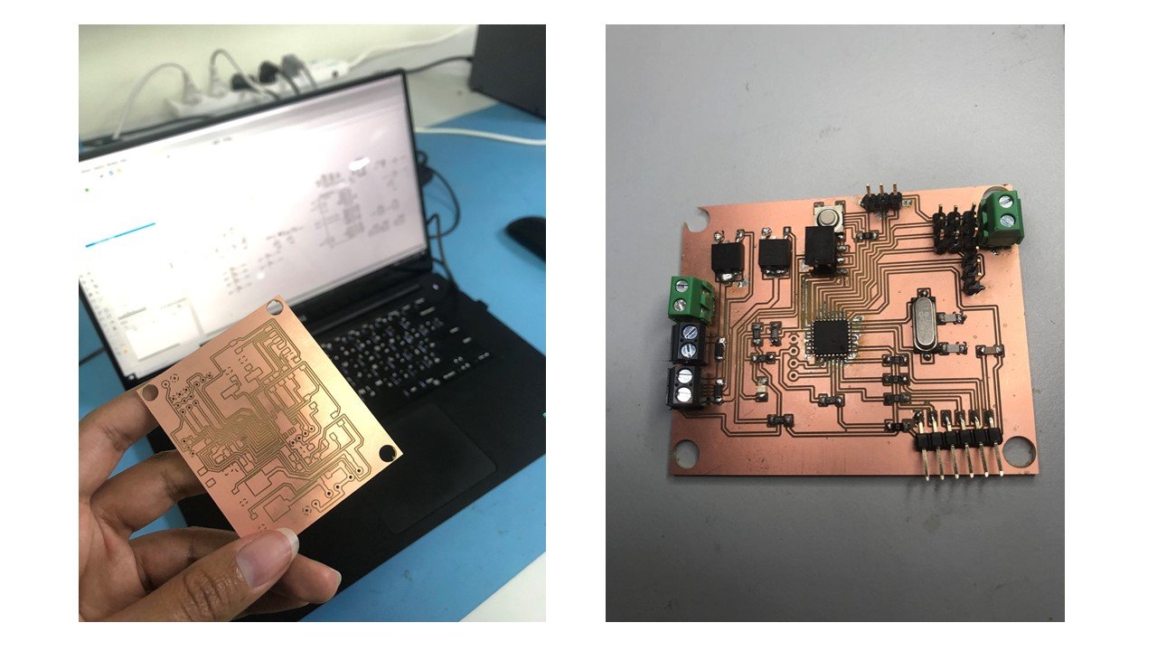
b. Fabrication:
I used FlatCAM software and followed the steps written in electronics design week to generate the CNC code for the outline and border, which the Renold SMR-20 CNC machine can understand. To create the holes, I follow the steps in the Output Devices week. Then, I follow the steps electronics production week to mill the PCB using the Renold SMR-20 CNC machine. After soldering, the PCB is shown below.
c. Programmming:
After burning bootloader using USBtinyISP, I uploaded the following code to the ATmega328 board. Then, I connected the input and output devices as follow:
1- The first servo motor: GND, VCC, PD5 (pin 13).
2- The second servo motor: GND, VCC, PB1 (pin 9).
4- The RTC: GND, VCC, SCL to pin PC5, SDA to pin PC4.
5- The first ultrasonic sensor: GND, VCC, PD6 (pin 6), PD7 (pin 7).
6- The second ultrasonic sensor: GND, VCC, PB0 (pin 8), PB3 (pin 11).
Then, I connected the battery to the regulator board and the main board since these devices draw considerable power.
#include "DS3231.h"                           // RTC Library
#include "Servo.h"                            // Servo motor library
#include "Wire.h"                             // I2C Communication

#define trig1 6
#define echo1 7
#define trig2 8
#define echo2 11
DS3231 rtc(SDA, SCL);
Time t;
Servo myfirstservo;
Servo mysecondservo;
int h;
int m;
int s;
float t1=0;
float d1=0;
float t2=0;
float d2=0;

void setup() {

  Serial.begin(9600);
  Wire.begin();
  rtc.begin();
 // rtc.setTime (11, 38,0);                     // set the time
  delay(2000);

  myfirstservo.attach(13);                      // The first CR servo motor is attached to PD5 (pin 5) in ATMEGA328
  mysecondservo.attach(9);                      //  The second CR servo motor is attached to PB1 (pin9) in ATMEGA328

  pinMode (trig1,OUTPUT);
  pinMode (echo1,INPUT);
  pinMode (trig2,OUTPUT);
  pinMode (echo2,INPUT);

}

void loop() {

  t= rtc.getTime ();
  h= t.hour;
  m= t.min;
  s= t.sec;

  digitalWrite(trig1,LOW);
  digitalWrite(trig2,LOW);
  delayMicroseconds(2);
  digitalWrite(trig1,HIGH);
  digitalWrite(trig2,HIGH);
  delayMicroseconds(10);
  digitalWrite(trig1,LOW);
  digitalWrite(trig2,LOW);
  t1=pulseIn(echo1,HIGH);
  t2=pulseIn(echo2,HIGH);
  d1= t1 * 0.0340 / 2;
  d2= t2 * 0.0340 / 2;

  if (h==4 && m==30 && s==0) {

     if (d1<10 && d2=10){
         myfirstservo.writeMicroseconds(1200);
         mysecondservo.writeMicroseconds(1800);
         delay(2000);
     }

     if (d1=10 && d2<10){
         myfirstservo.writeMicroseconds(1800);
         mysecondservo.writeMicroseconds(1200);
         delay(2000);
     }

    else {
         myfirstservo.writeMicroseconds(1500);
         mysecondservo.writeMicroseconds(1500);
         delay(1000);
    }

  }


}
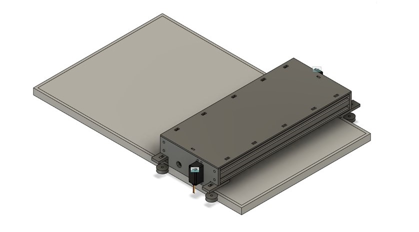
2. Computer-aided Design
I 3D-designed the robot using Fusion 360 as shown below.
3. Fabrication
I started by 3D printing the wheels with two materials: TPE Filament (outter part) and PLA Filament (inner part). Then, I connected the four wheels to the microfiber brushes.
I laser cut the side faces of the robot to the designed shape and the aluminum profiles to the same length as the solar panels. After that, I assemble all parts.
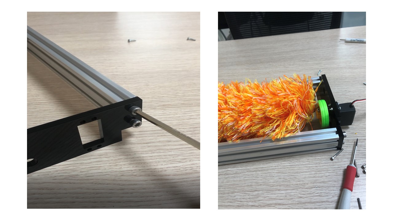
Finally, I lase cut the electronics box and the robot cover and assemble them.
Final Thoughts
This project was succesful because the solar-panels cleanign robot is able to clean surfaces from accumulated dust and dirt by microfiber brush. The main code of the ATmega328 board is working. Thus, the servo motors move after receiving signals from the real-time clock (RTC) and the ultrasonic sensors. Moreover, the robot moves in straight line and the brushes are rotating to clean the panels while this motion. In my opinion, I think this project is open to adjustments that includes changing the position of the ultrasonic sensors, study how effective is this robot, and using compressed air duster in the robot to get better results.
# Files:
1- ATmega328 Board .brd
2- ATmega328 Board .sch
3- Regulator Board .brd
4- Regulator Board .sch
5- The Robot 3D design