11. Output Devices
# Goal:
Add an output device to a microcontroller board using Eagle software and CNC machine. Then, program the device using Arduino IDE.
# Tasks:
1- Design my final project ATmega328 board using Eagle software.
2- Creat the PCB using a CNC machine and solder the components.
3- Connect the servo motors to ATmega328 board and program it using Arduino IDE .
# Procedures:
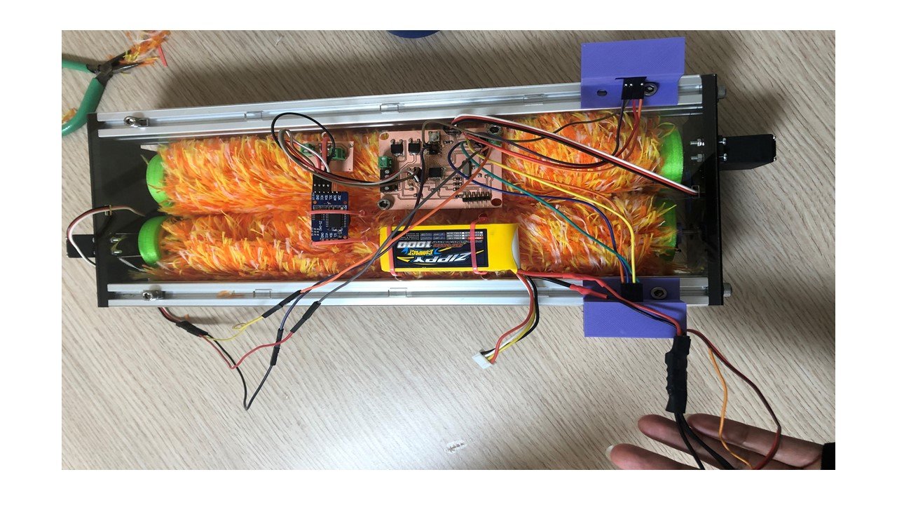
This week I designed my final project board to control my solar panel cleaning robot using Eagle software and a CNC machine. To move this robot and rotate the brushes, I needed two continuous rotation servo motors. Also, I utilized a DC motor to pump the water to facilitate cleaning the solar panel. Then, I connected these motors to the PCB and used the Arduino IDE to program and control them.
a. Designing:
To start the designing process, I chose to fabricate an Ardiuno Uno-like board using ATmega328 microcontroller. After I created a new project and opened the schematic screen on Eagle software, I used the "Add Part" tool to add the components of the board, which are shown below.
| Component | Quantity |
|---|---|
| ATmega328 | 1 |
| 10kΩ Resistors | 3 |
| 499Ω Resistors | 1 |
| 0Ω Resistors | 6 |
| FTDI | 1 |
| Terminal Block | 6 |
| Button | 1 |
| Green LED | 1 |
| Resonator | 1 |
| Diode | 2 |
| N-type MOSFET | 2 |
| 0.1 uF Capacitor | 2 |
| 10 uF Capacitor | 1 |
| 10 pF Capacitor | 2 |
| Regulator | 1 |
| 2x3 Pin header | 1 |
| 4 Pin header | 1 |
| 3 Pin header | 5 |
I used the "Net" and "Name" tools to connect the electrical parts and name the paths, respectively. This is the resulting schematic diagram of the board.
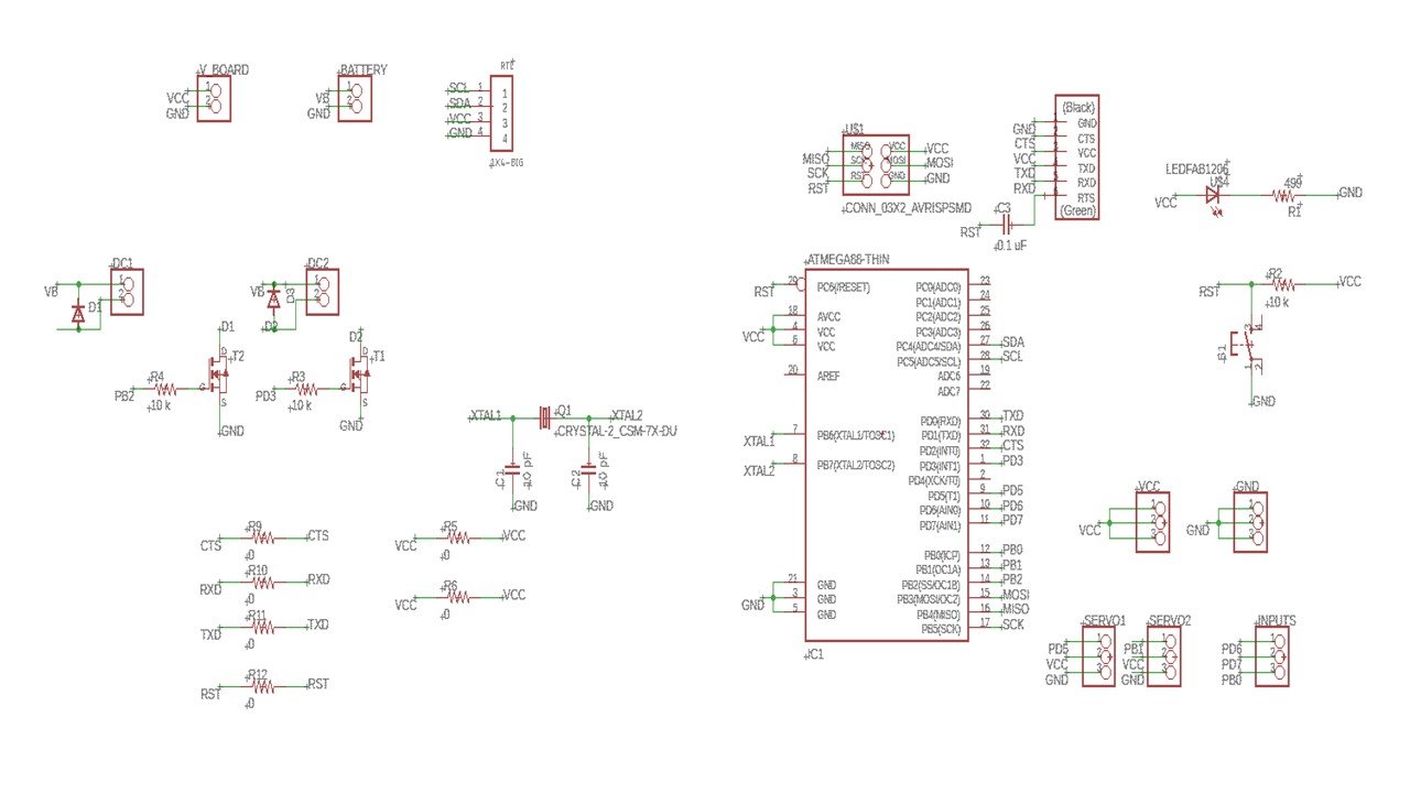
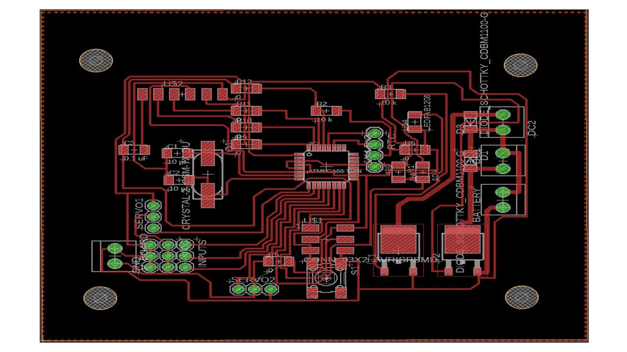
I created the board layout using the "Generate/Switch to board" button and connected the components as shown below. Then, I adjusted the clearance dimensions and distance to 16 mils and the minimum width and drill to 12 mils, using the design rule check. After I received a "No Error" message, I saved the files.
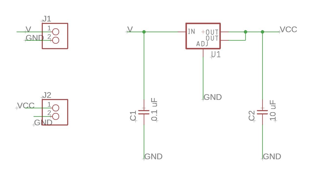
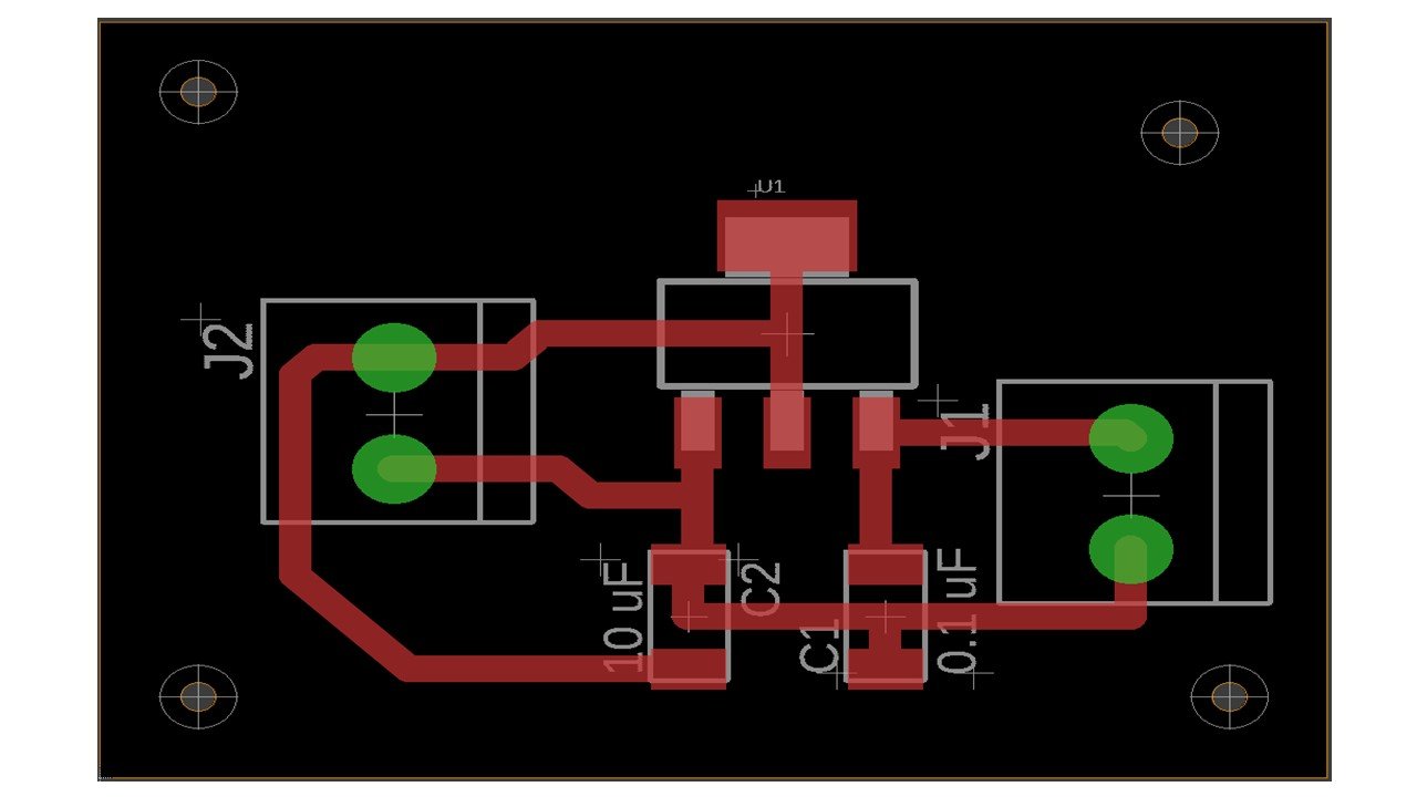
Then, I created a sideboard to regulate the battery voltage using a regulator.
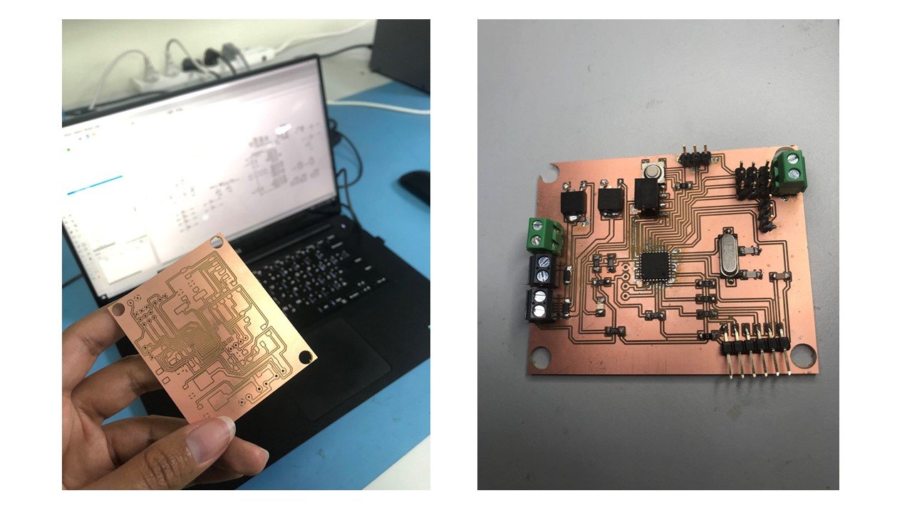
b. Fabrication:
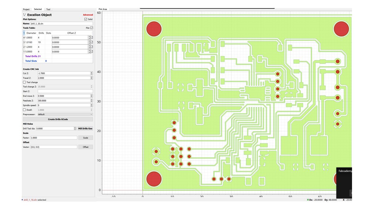
I transferred the Eagle files to CNC code files, which the Renold SMR-20 CNC machine can understand. To generate the CNC code, I used FlatCAM software and followed the steps written in the electronics design week for the outline and border. To create the holes, I opened the Excellon file "drill_1_16.xln". Then, I pressed "selected" to adjust the settings. I started by fixing the Z-axis cut to be -1.7. After that, I clicked on "Create Drills GCode", and saved the CNC code.
Moving to the Renold SMR-20 CNC machine, I started by placing an FR1-MDF board inside the machine and ensuring it was flat using the screws. Before milling, I changed the milling bit of the machine using a screwdriver to 1/64 milling bit for the outline and 1/32 for the frame and holes. Then, I selected the origin point (X, Y, Z) based on the available space on the board. After that, I clicked on the "Cut" button and added the CNC code files. I start milling the outline, holes, then the border. After the milling process finished, I soldered the components. To avoid having a short circuit, I removed the excess solder and checked the ends of the components using a multimeter.
c. Programmming:
To program my ATmega328 board, I connected it to a previously programed FabTinyISP by a ribbon cable with two 2x3 connectors. In Arduino IDE software , I clicked on Tools and change "Board" to "Arduino/Genuino Uno", and "Processor" to "USBtinyISP". After that, I clicked on "Burn Bootloader".

I connected the two continuous rotation servo motors and the DC motor using wires, as shown below. Each continuous rotation servo motor has three wires: ground, power, and signal. These wires have different colors. The ground wire is black or brown, and must be connected to the ground in the board. Typically, the power wire is red, and must be connected to the VCC or the 5V on the board. Finally, the signal wire can be white, orange, or yellow and must be connected to a PWM pin. In my board, these PWM pins are PD5 and PB1 for the first and second servo, respectively. Moving to the second output: DC motor. The function of the DC motor is facilitate water pumping. Since the direction of DC motor rotation is not important to my final project, I connected this motor to a MOSFET.Then, I connected this MOSFET to a PWM pin. A DC motor has two wires: power and ground. The power and ground wires typically are red and black, respectively. In addition, I connected the battery to the regulator board and the main board since the two servo motors and the DC motor draw considerable power.
1. Continuous Rotation Servo Motor:
To control the continuous rotation servo motors, I used the servo library.This library can control up to 12 servo motors utilizing only a single timer. Also, it is compatible with various microcontrollers, such as AVR, and Arduino boards including Arduino Uno. Servo motors contain integrated gears and a shaft that can be precisely controlled. Unlike the typical servo's shaft that is controlled by 0 to 180 degrees angle, continuous rotation servo's shaft is rotated by different speeds.
I defined the two variables: the two continuous rotation servo motors. I named them "myfirstservo" and "mysecondservo". Then, I used the "attach (pin)" function to set each variable to the attached pin in the void setup. The first servo is attached to pin number 13, while the second to pin 9.
In the void loop section, I used the "writeMicroseconds" function to rotate the brushes connected to the motors. As a result, the robot moved forwards and backward. This function accepts values between 1000, for full speed counterclockwise rotation, and 2000, for full speed clockwise rotation, for a continuous rotation servo motor. A 1500 microsecond value causes the motor to stop rotating. I used intermediate values to aviod the speed limits. These values are 1200, for counterclockwise rotation, and 1800, for clockwise rotation. Then, I used the "delay" function to allow the motors to rotate for 2 seconds.
// This code describe how to control two continuous rotation servo motors.


#include "Servo.h"                             // To use the Servo motor library

Servo myfirstservo;                            // Define the first servo motor

Servo mysecondservo;                           // Define the second servo motor


void setup() {

       // put your setup code here, to run once:


       myfirstservo.attach(13);                // The first CR servo motor is attached to PD5 (pin 13) in ATMEGA328

       mysecondservo.attach(9);                // The second CR servo motor is attached to PB1 (pin 9) in ATMEGA328

}


void loop() {

      // put your main code here, to run repeatedly:


                                                  // To allow the brushes to move clockwise (robot moved backwards)

      myfirstservo.writeMicroseconds(1200);

      mysecondservo.writeMicroseconds(1800);

      delay(2000);                                // allow to rotate for 2 sec


                                                  // To allow the servo motors to stop for 1 sec
      myfirstservo.writeMicroseconds(1500);

      mysecondservo.writeMicroseconds(1500);

      delay(1000);


                                                // To allow the brushes to move  counter clockwise (robot moved forwards)

      myfirstservo.writeMicroseconds(1800);

      mysecondservo.writeMicroseconds(1200);

      delay(2000);                             // allow to rotate for 2 sec

}
Group Assignment
The link of the group assignment page is here.
# Goal:
Measure the power consumption of the continuous Rotation Servo Motor
# Task:
Measure the voltage and current of the Servo motor then calculate the power.
# Procedures:
After connecting the motor with the ATmega328 board, I used a multimeter to measure the voltage and got 5V. Then, I measured the current, and the reading was 0.03A. So, the power consumption of the motor equals the multiplication of the current and voltage: 5V*0.03A= 0.15W
# Challenges:
The main challenge I faced was during the designing process of my final project board. The time needed to finalize that process was longer than I expected.
# Files:
1- Schematic Design
2- Board
3- Final Board Traces
4- Final Board Outline