13. Input Devices
# Goal:
Add a sensor to the ATmega328 board and read it
# Tasks:
1- Connect a real time clock (RTC) to ATmega328 board and program it using Arduino IDE .
2- Connect an Ultrasonic sensor to ATmega328 board and program it using Arduino IDE .
# Procedures:
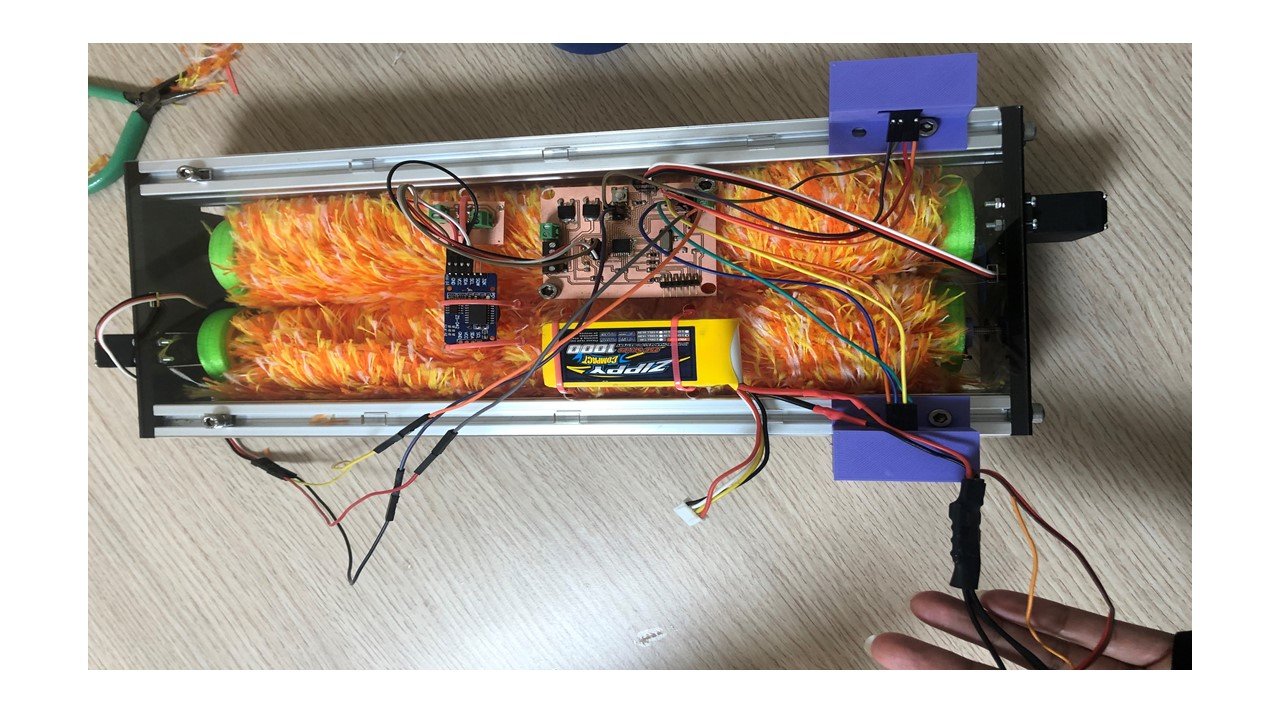
I chose to add a real-time clock (RTC) module to set an alarm, and an ultrasonic sensor to measure the distance as the input devices for my final project. Thus, I connected these input devices to the ATmega328 board designed in the output devices week. Then, I used the Arduino IDE to program and control these input devices.
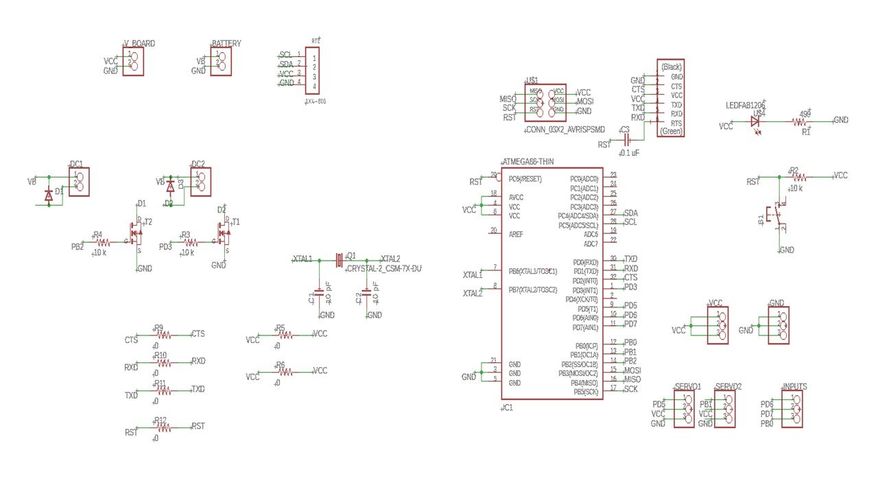
The ZS-042 RTC operates using I2C communication. I connected it to the ATmega328 board by four female-to-female wires. I started by wiring the ground (GND) of RTC to the board's ground. Then, I wired the VCC of the RTC to the board's power, which is called VCC as well. After that, I connected the serial clock (SCL) to pin PC5 and the serial data (SDA) to pin PC4. Likewise, the Ultrasonic distance measuring sensor was connected to the ATmega328 board by four female-to-female wires. Ultrasonic Sensor HC-SR04 works by emitting an ultrasound in the air that bounces back if there is an object. By measuring the speed and the time, the distance is calculated. This sensor has four pins: VCC, GND, TRIG, and ECHO. Thus, I wired the power and ground of the sensor with the power and ground pins of the board. The trigger pin generates the ultrasound wave. This wave will, late on, be received by the Echo pin. Both of these pins can be connected to any digital I/O pin. In my case, I connected TRIG and ECHO with additional input pins PD6, and PD7, respectively. The wiring of the input devices are shown below.
a. Real Time Clock:
To control the RTC module, I used the DS3231 library.This library can used clock reading, clock setting, and alarms. Also, it is compatiable with all architectures and Arduino boards. Also, I used the Wire library to communicate with I2C devices such as RTC. In addition to the previous two libraries, I used the Servo library to prove the alarm function of the code.
I defined the five variables: the rtc, time (t), hours (h), minutes (m), and seconds (s). In the void setup section, I opened the serial port and adjusted the data rate to 9600 bps. Then, I used the "Wire.begin" function to prepare few buffers to store data including the speed of communication and interrupting the I2C bus. To start using the RTC library methods, I declared the "rtc.begin" function. Then, I adjusted the time to 11:38 AM.
In the void loop section, I used the "getTime" function to read the time. Then, I define the hour, minute, and seconds in that reading and print them on the serial monitor. In my code, I would like the robot to move when the time is 11:45 AM. Thus, I included an if condition to allow the CR servo motors to rotate at that specific time.
// This code describe how to control an RTC module.


#include "DS3231.h"                                     // RTC Library
#include "Wire.h"                                       // I2C Communication
#include "Servo.h"                                      // Servo motor library

Servo myfirstservo;                                     // Define the first servo motor
Servo mysecondservo;                                    // Define the second servo motor

DS3231 rtc(SDA, SCL);                                   // Declare the RTC object
Time t;                                                 // Declare time
int h;                                                  // Declare hours integer
int m;                                                  // Declare minutes integer
int s;                                                  // Declare seconds integer

void setup() {
  // put your setup code here, to run once:

  Serial.begin(9600);                                  //Opens serial port, sets data rate to 9600 bps
  Wire.begin();
  rtc.begin();
  rtc.setTime (11, 38,0);                              // Set the time
  delay(2000);                                         // Allow to set the time for 2 sec
  myfirstservo.attach(13);                             // The first CR servo motor is attached to PD5 (pin 5) in ATMEGA328
  mysecondservo.attach(9);                             // The second CR servo motor is attached to PB1 (pin 9) in ATMEGA328

}

void loop() {
  // put your main code here, to run repeatedly:

  t= rtc.getTime ();                                   // Read the time using the function "getTime" from library
  h= t.hour;                                           // Hours in the readed time
  m= t.min;                                            // Minutes in the readed time
  s= t.sec;                                            // Seconds in the readed time
  Serial.print(h);                                     // Print the time in [hours:min.sec] from the serial monitor
  Serial.print(":");
  Serial.print(m);
  Serial.print(".");
  Serial.println(s);

  if (h==11 && m==45 && s==0){                         // If the time is 11:45 AM, the CR servo motors start to rotate

       myfirstservo.writeMicroseconds(1200);
       mysecondservo.writeMicroseconds(1800);

    }
  }
b. Ultrasonic Distance Measuring sensor:
I started with defining the Atmega328 pins connected to the trigger and the echo pins of the sensor. Then, I declared the two variables: time and distance. In the void setup, I opened the serial port and adjusted the data rate to 9600 bps, and stated the trigger pin as an output and the echo pin as an input.
In the void loop section, I used the "digitalWrite" function to clear the trigger pin and activate it for 10 microseconds. After that, I used the "pulseIn" function to measure the travel time of the wave (us) . Then, I calculated the distance (cm) from the measured time using this formula: d=(t*c)/2, where c is the speed of the sound wave in the air and equals 340 m/s.
// This code describe how to control an Ultrasonic sensor.


#define trig1 6                                   // Define the ATmega328 pin attached to the trigger pin in the sensor
#define echo1 7                                   // Define the ATmega328 pin attached to the echo pin in the sensor


float t1=0;                                      // Declare the time period from emitting ultrasound wave til receiving it
float d1=0;                                      // Declare the distance


void setup() {
  // put your setup code here, to run once:

  Serial.begin(9600);
  pinMode (trig1,OUTPUT);                       // Declare the Trigger pin as an output
  pinMode (echo1,INPUT);                        // Declare the Echo pin as an input

}

void loop() {
  // put your main code here, to run repeatedly:

  digitalWrite(trig1,LOW);                     //Clear the trigger pin condition for 2 microseconds
  delayMicroseconds(2);
  digitalWrite(trig1,HIGH);                    //Activate the trigger pin for 10 microseconds
  delayMicroseconds(10);
  digitalWrite(trig1,LOW);
  t1=pulseIn(echo1,HIGH);                     // Measure the wave travel time based on the echo pin reading
  d1= t1 * 0.0340 / 2;                        // Calculate the distance in cm based on travel time and speed of sound wave
  Serial.println(d1);                         // Displays the distance on the serial monitor

}
Group Assignment
The link of the group assignment page is here.
# Goal:
Probe an input device's analog levels and digital signals.
# Task:
Observe the change of the voltage using oscilloscope.
# Procedures:
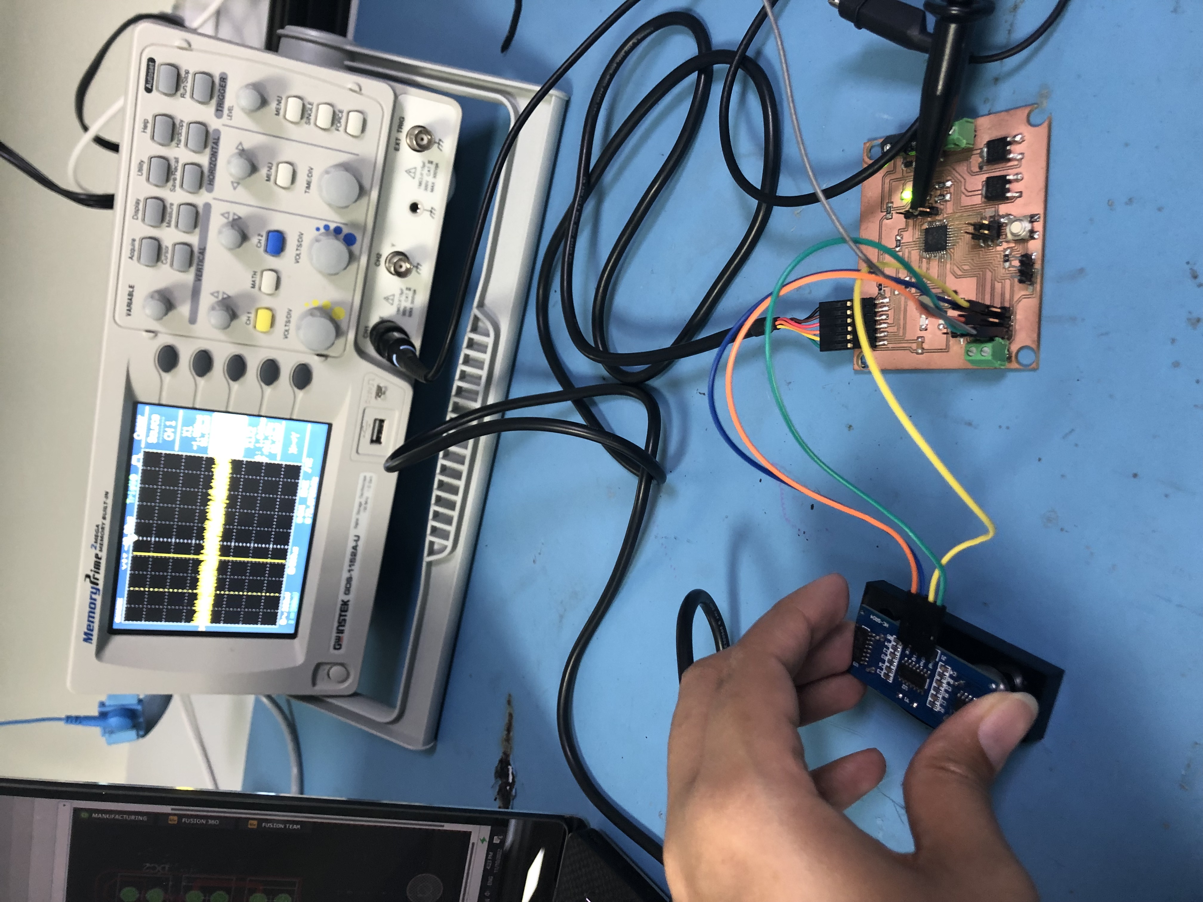
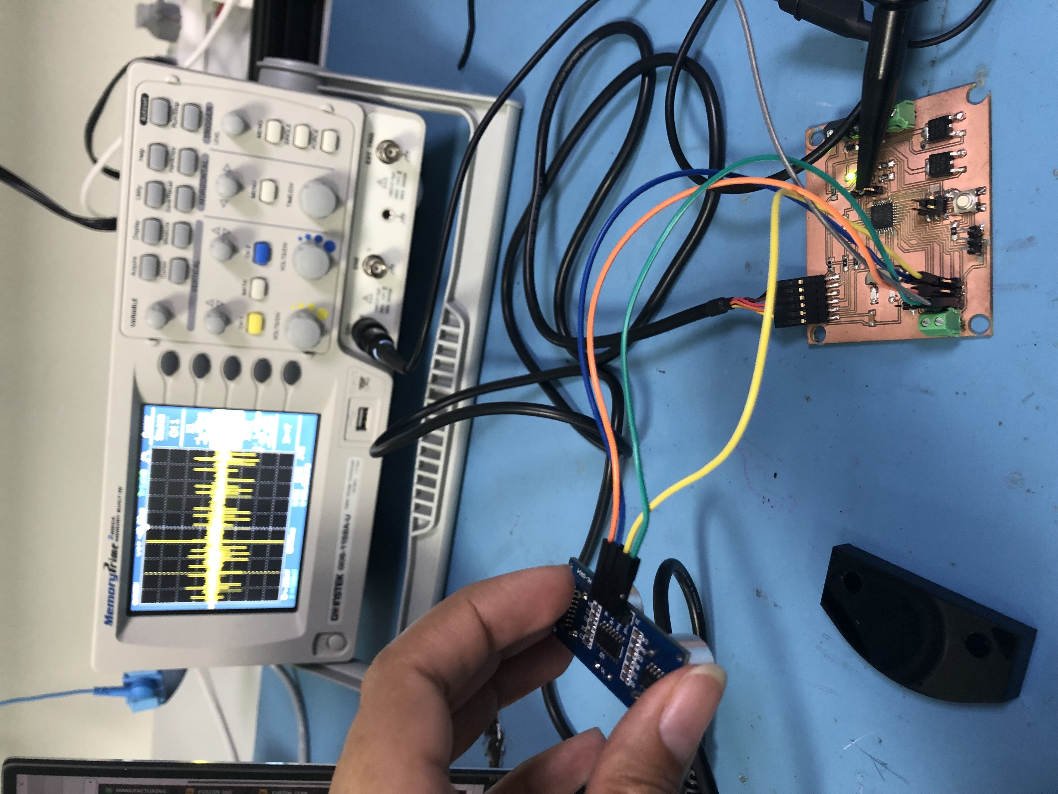
In the input week, I connected Ultrasonic Distance Measuring sensor as an input device to my ATmega328 board. So, I wanted the observe the change in the voltage signal using an oscilloscope as the distance change.
# Challenges:
The main challenge I faced was figuring out the codes of the input devices, since it was my first time using RTC and Ultrasonic sensor.