12 - Input Devices
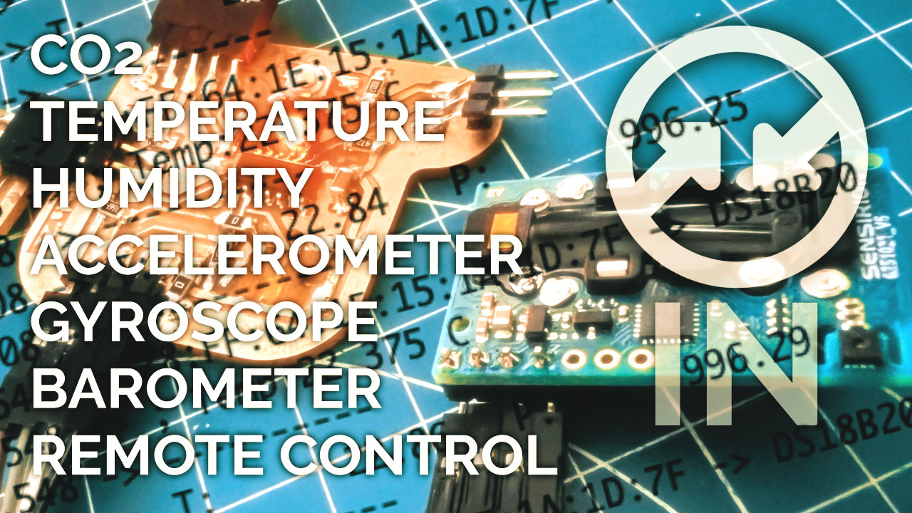
This week we have learned input devices. I have used temperature sensors, CO2, accelerometer, barometer....
Summary
This week we have learned input devices. This week I have used temperature sensors, CO2, accelerometer, barometer….
Assigments
- individual assignment:
- measure something: add a sensor to a microcontroller board
- that you have designed and read it - group assignment:
- probe an input device’s analog levels and digital signals
Group Assigment
The link to Group Assignments of Fab Lab León is this
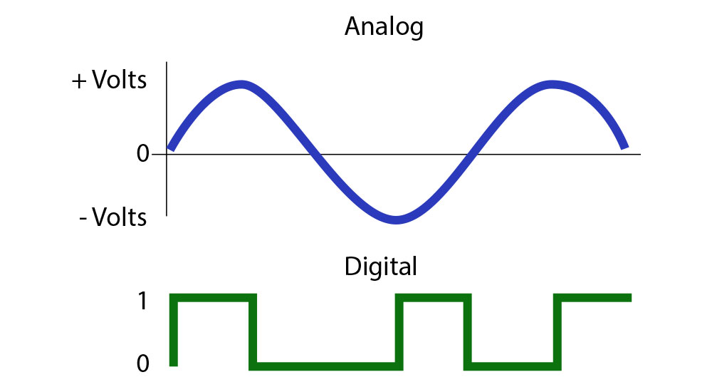
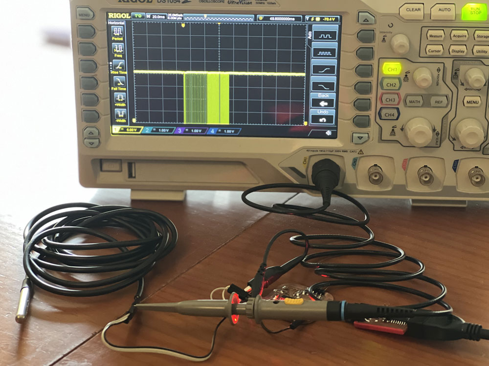
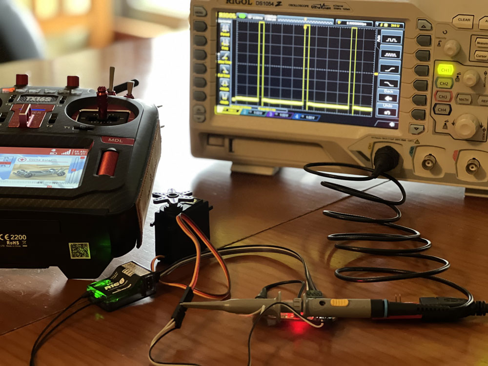
This week we have to probe the analog and digital signals from an input device. Probing is the act of measuring the structure and duration of a pulse. This can be done with test probes. The main difference between analog and digital signals is that analog signals have continuous electrical signals while digital signals have non-continuous electrical signals.
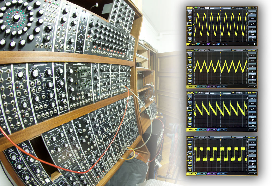
I work with oscilloscope to read signals.
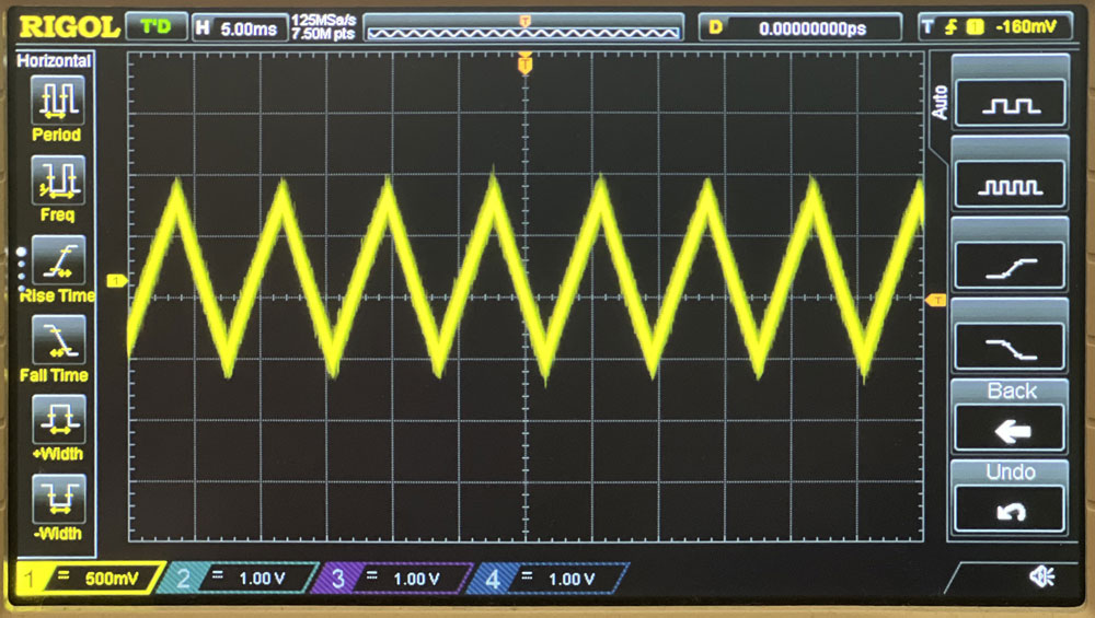
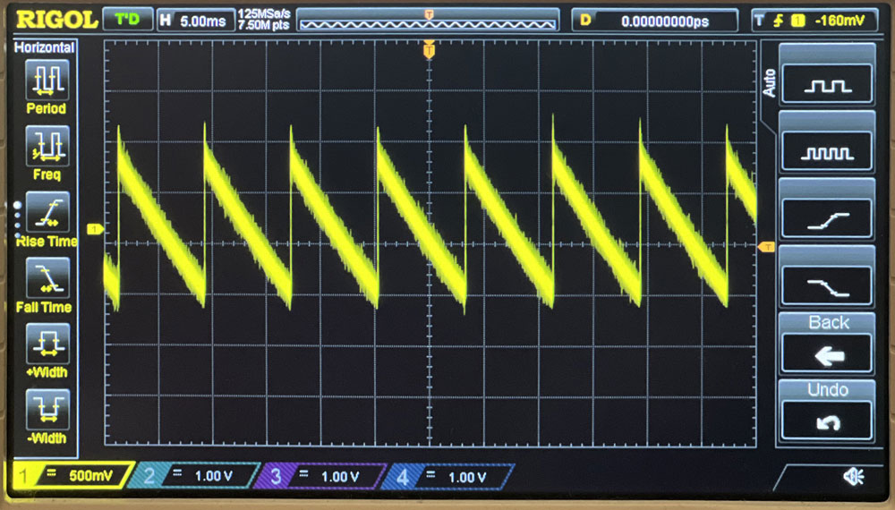
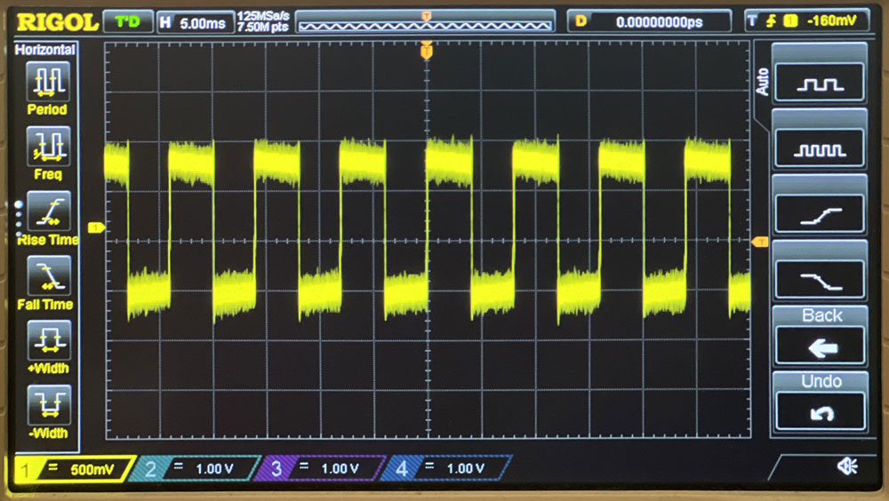
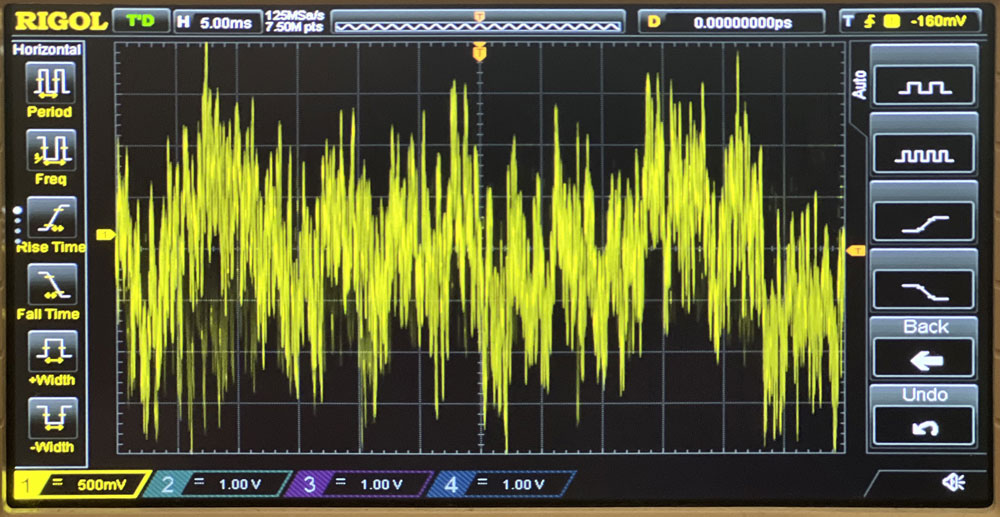
Analog signal
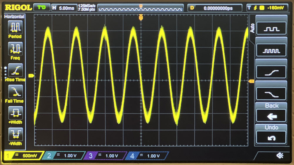
With my modular synth I read the diferent analog signal from oscillators (VCO): sine wave, triangle, raw, pulse and a noise. Sounds delicious!.
Digital signal
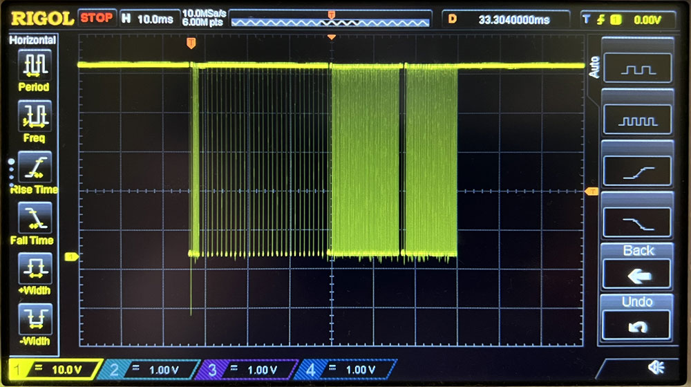
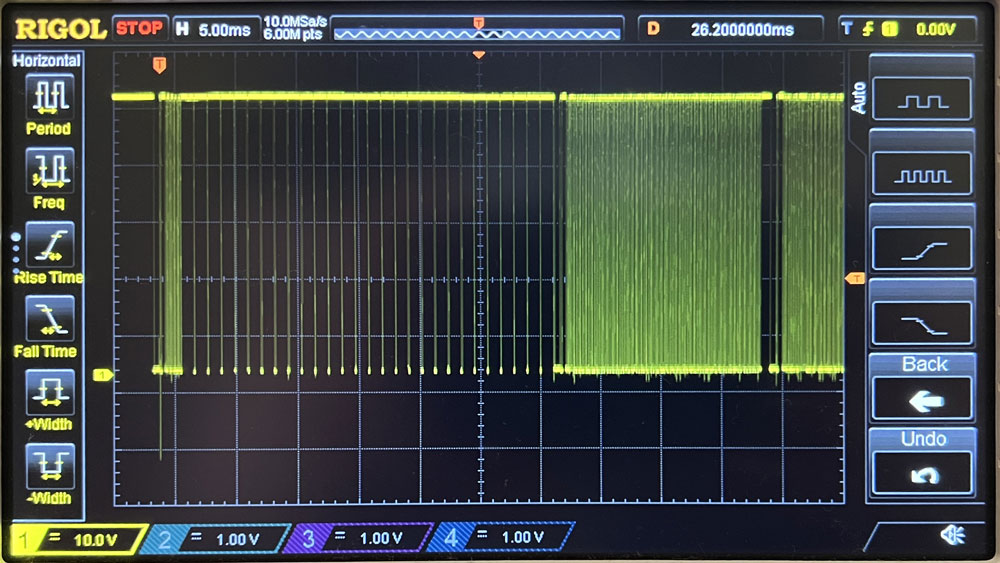
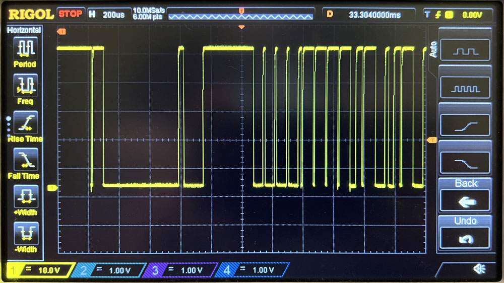
The digital signal from temp sensor. The temperature sensor uses the 1-Wire protocol. 1-Wire is a voltage-based digital system that works with two contacts, data and ground, for half- duplex bidirectional communication.
PWM
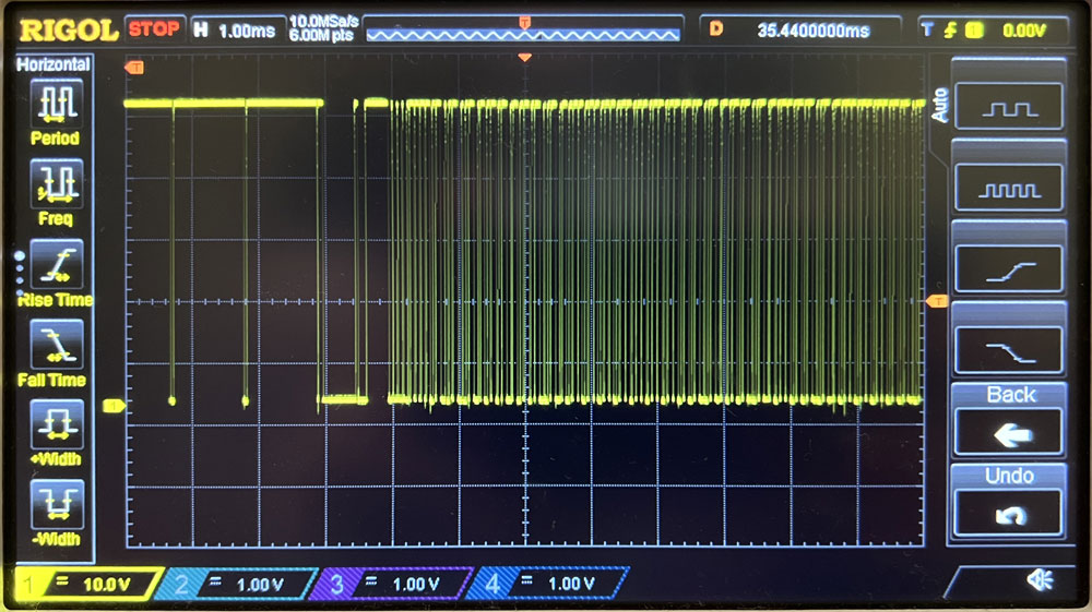
And read the digital reciver rc data (PWM) from channel 3 same I use in the sketch of remote control. The width of the pulse varies depending on the amount of stick position, between 988µs and 2012µs.
Individual Assigment
I have proposed 3 mini projects to work with inputs.
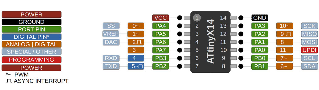
One is to use Attiny1614 for my final project, with the temperature sensor by OneWire and the accelerometer, barometer and gyroscope of the GY86 board by I2C.
Also using the Attiny1614 itself, read data from an SCD30 sensor to measure CO2 levels.
And finally, a power control of a solar vehicle managed by radio control, reading the values of the radio, from an RC receiver and INA219 to measure the power and optimize the maximum performance.
In addition to the design of a pcb with a SAMD21E microcontroller and apply it to the same previous examples.
Temperature Sensor
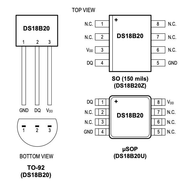
The DS18B20 Sensor is a device used to measure temperature. This can be air temperature, liquid temperature or the temperature of solid matter.
The DS18B20 digital thermometer provides 9-bit to 12-bit Celsius temperature measurements and has an alarm function with nonvolatile user-programmable upper and lower trigger points. The DS18B20 communicates over a 1-Wire bus that by definition requires only one data line (and ground) for communication with a central microprocessor. In addition, the DS18B20 can derive power directly from the data line (“parasite power”), eliminating the need for an external power supply.
What Is Special About 1-Wire?
1-Wire is a voltage-based digital system that works with two contacts, data and ground, for half- duplex bidirectional communication. Compared to other serial communication systems such as I2C or SPI, 1-Wire devices are designed for use in a momentary contact environment. Either disconnecting from the 1-Wire bus or a loss of contact puts the 1-Wire slaves into a defined reset state. When the voltage returns, the slaves wake up and signal their presence. With only one contact to protect, the built-in ESD protection of 1-Wire devices is extremely high. With two contacts, 1-Wire devices are the most economical way to add electronic functionality to nonelectronic objects for identification, authentication, and delivery of calibration data or manufacturing information.
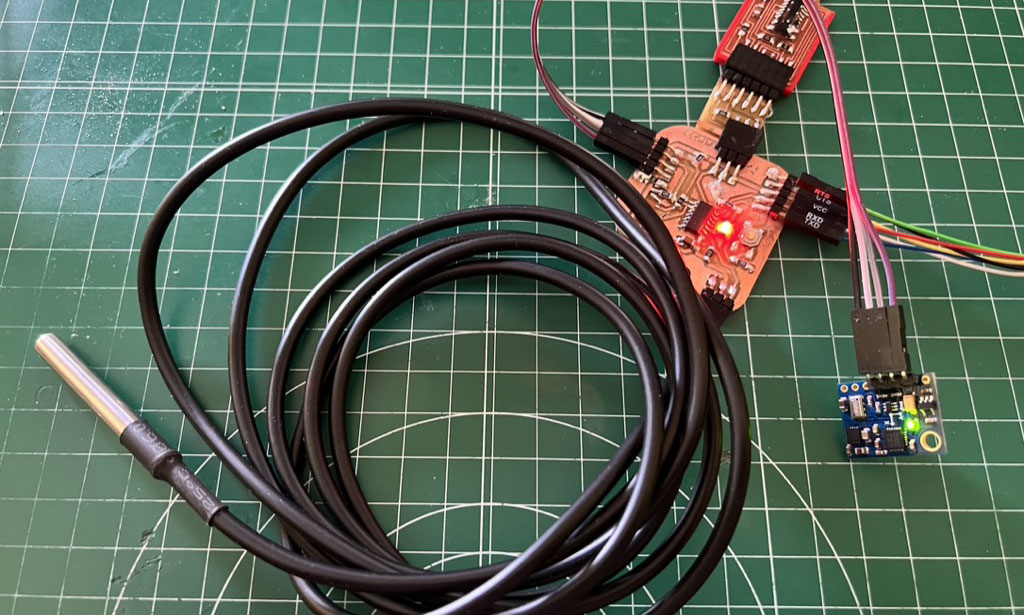
The DS18B20 temperature sensor is one of the most versatile sensors you can find on the market.
This sensor is ideal when we want to measure the temperature in humid environments and even in water. This is because we can buy a version that comes in the form of a waterproof probe.
Perhaps the most complicated part is the programming since it uses a protocol that is not very common in the world of Arduino, 1-Wire.
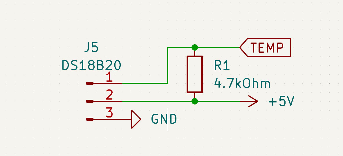
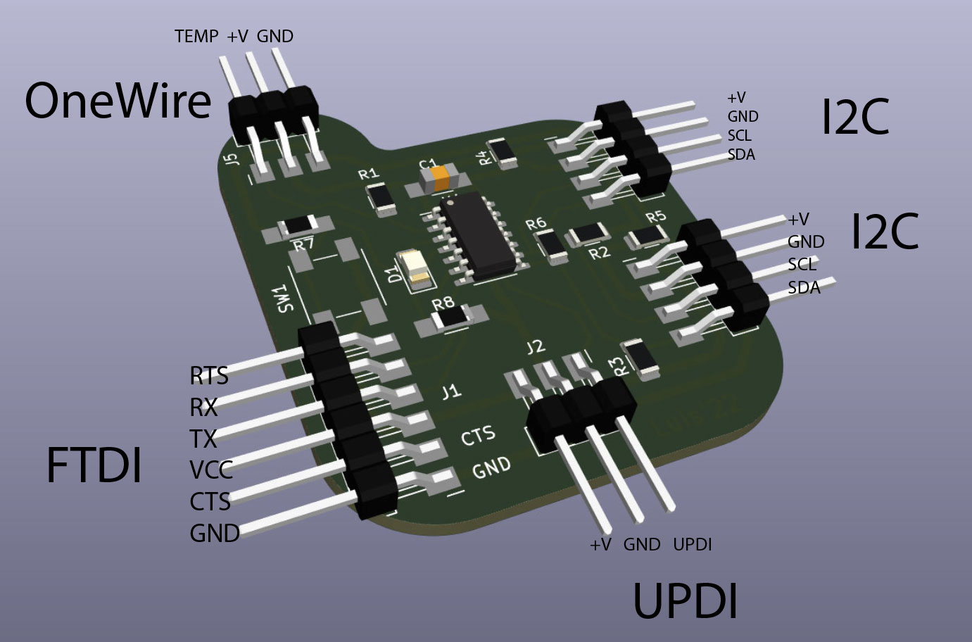
It is necessary to put a pull up resistor between the data pin and the VIN pin. I have already prepared this on the pcb that I had designed for Outputs Devices week.
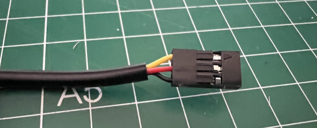
Dupont connectors
“DuPont connector” is a vernacular term which refers to a number of different types of 0.1″ pitch connector. They feature black plastic housings which retain contacts with fingers built into the housing body. All are very similar in appearance but vary significantly in quality and price.
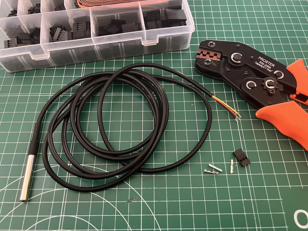
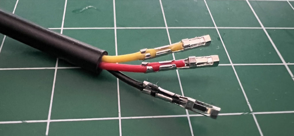
To make the cables with this connector you need to have a crimping tool. In this case we will use 3 female connectors to connect the sensor to our PCB.
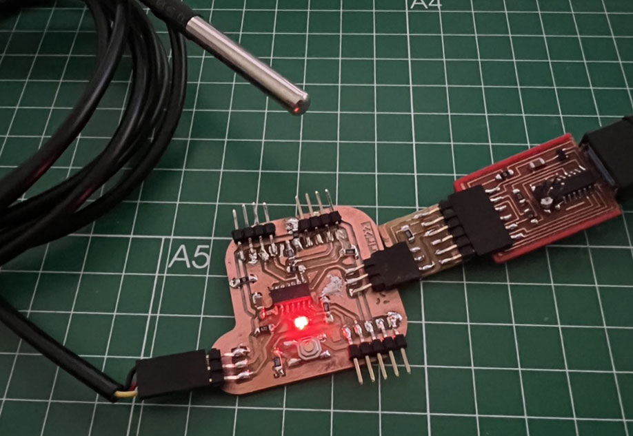
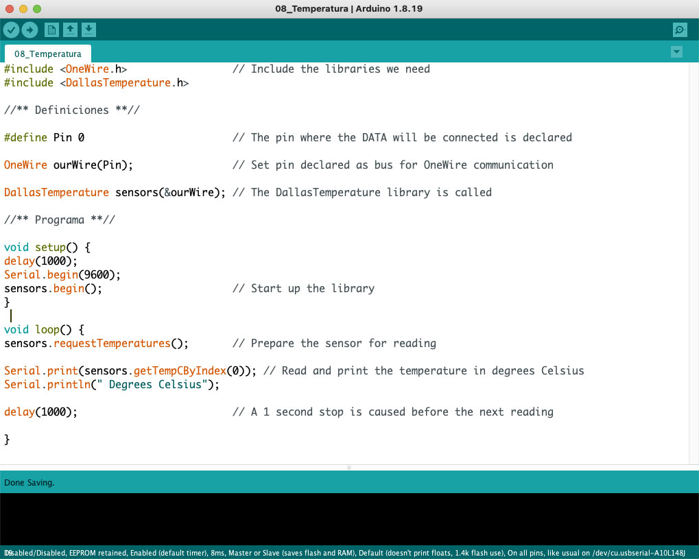
For Arduino can use a library “OneWire” and for use with the sensor use the “DallasTemperature”. I made this sketch 08_Temperatura (.zip).
Initially I was unable to get the serial monitor to work, I couldn’t remember to connect RX to TX and TX to RX.
It’s important to note that those RX and TX labels are with respect to the device itself. So the RX from one device should go to the TX of the other, and vice-versa. It’s weird if you’re used to hooking up VCC to VCC, GND to GND, MOSI to MOSI, etc., but it makes sense if you think about it.
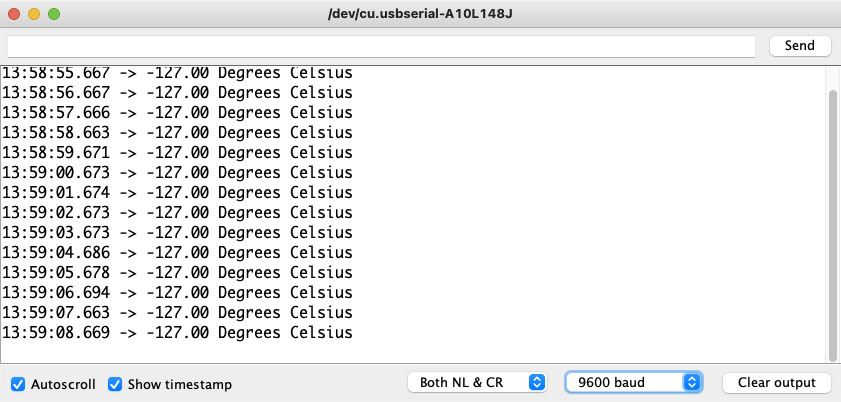
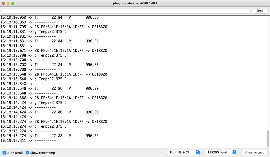
With this library dont work, but I try a new program for use Attiny1614 with the alternative library “OneWireNg” 09_Temperatura (.zip)
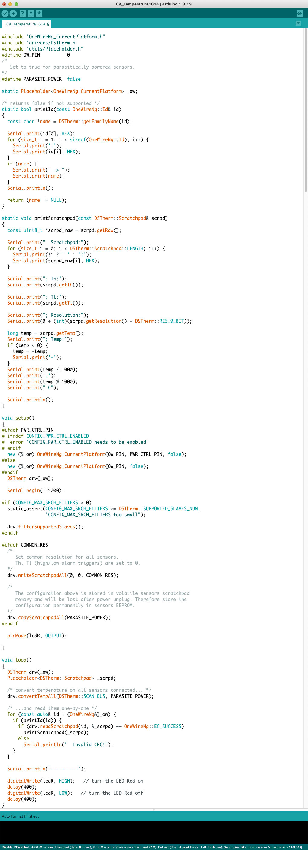
From serial monitor i read this values:
Sensor IMU GY-86
Small based on the sensor board of Invensense MPU-6050 (3-axis accelerometer and 3-axis gyroscope), digital 3-axis compass HMC5883L Honeywell and the pressure sensor resolution of the MS5611 MEAS. I²C standard communication protocol.
I try add the code for the previous temperature sketch, need use 2 libraries one for the MPU-6050 and other for the MS5611 10-11_Temp_GY86.
In this case of the sensor IMU GY-86 is connected with I2C.
After add the code, and try compile i recive a memory error. I can´t use the Attiny1614 with my final project, I need more program storage space.
But if I use a Attiny3224 will have space for use both libraries, i try compile for see the space used:
Sketch uses 17942 bytes (54%) of program storage space. Maximum is 32768 bytes.

Global variables use 409 bytes (13%) of dynamic memory, leaving 2663 bytes for local variables. Maximum is 3072 bytes.
For now I split this sketch in two project, one with temp & MPU-6050 and other with temp sensor and MS5611.
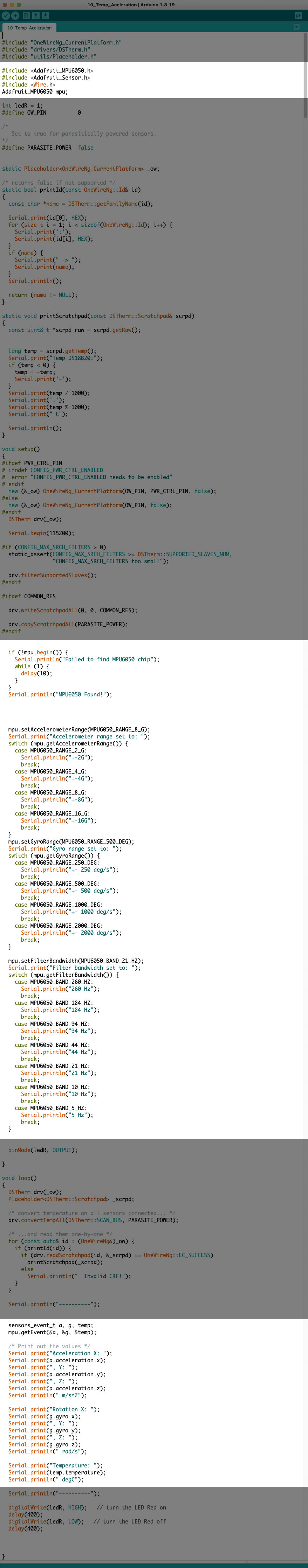
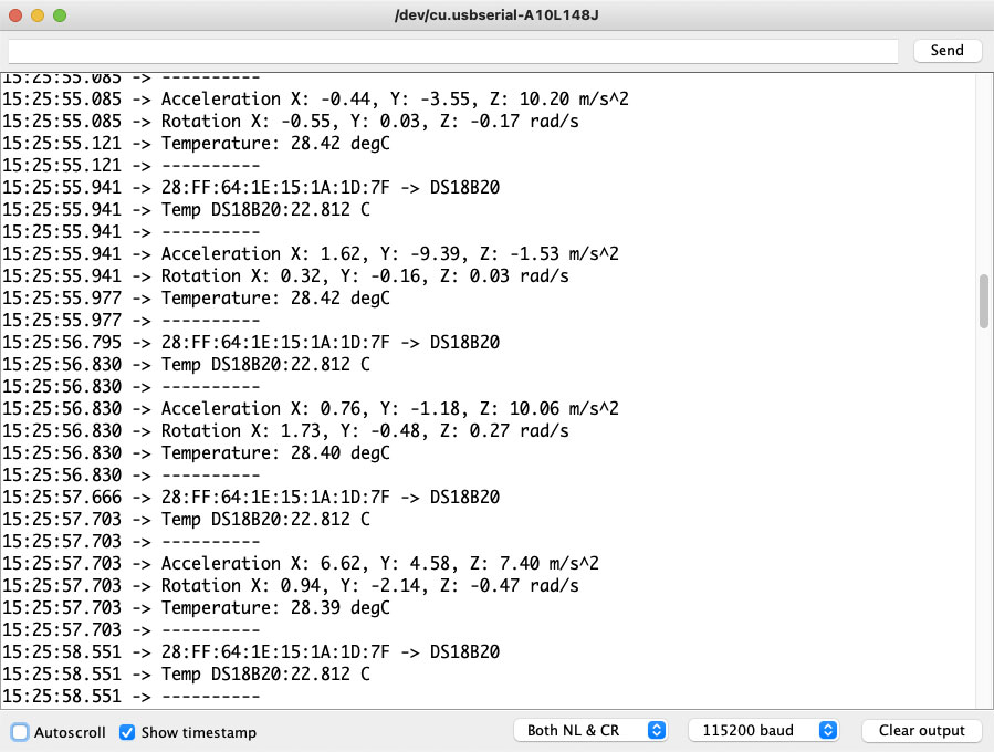
The first sketch with MPU-6050 (10_Temp_Aceleration). This sketch use the 95% of memory, I think if I use a Attiny3224 will have space for use both libraries.
Sketch uses 15575 bytes (95%) of program storage space. Maximum is 16384 bytes.

Global variables use 356 bytes (17%) of dynamic memory, leaving 1692 bytes for local variables. Maximum is 2048 bytes.
The serial monitor print:
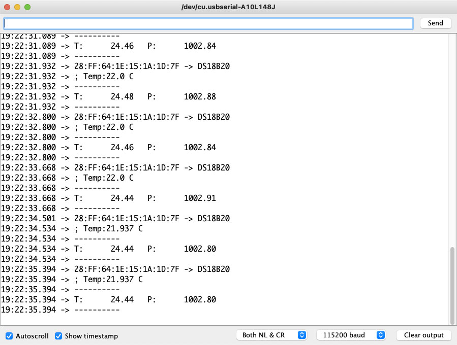
The second sketch with MS5611 (11_Temp-Baro).
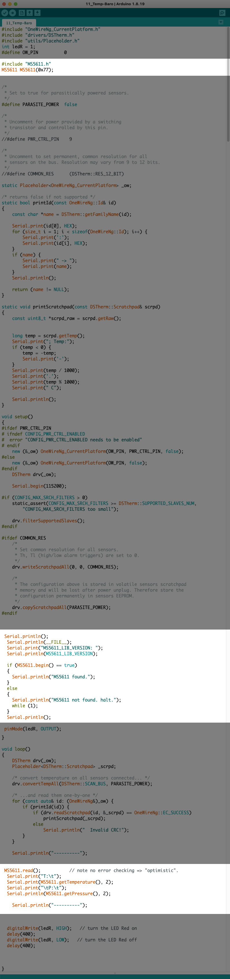
The serial monitor print:
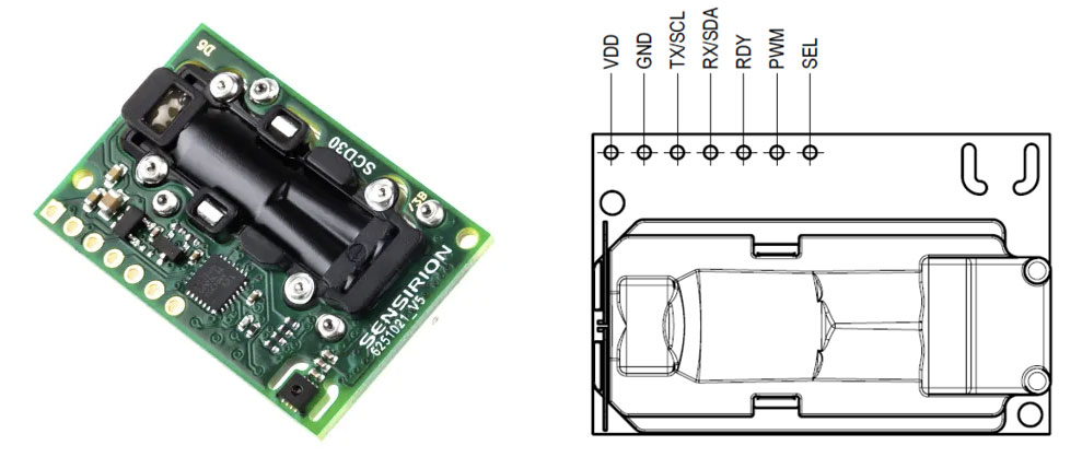
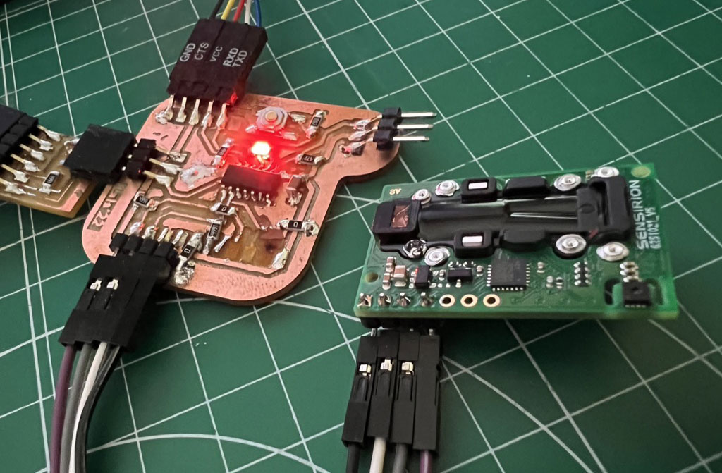
Sensirion SCD30
CMOSens® Technology for IR detection enables highly accurate carbon dioxide measurement at a competitive price. Along with the NDIR measurement technology for CO₂ detection, a best-in-class Sensirion humidity and temperature sensor is also integrated on the same sensor module. Ambient humidity and temperature can be outputted by Sensirion’s algorithm expertise through modeling and compensating of external heat sources without the requirement for any additional components.
Thanks to the dual-channel principle for the measurement of carbon dioxide concentration, the sensor compensates for long-term drifts automatically by design.
Carbon dioxide is a key indicator of indoor air quality. Thanks to new energy standards and better insulation, houses have become increasingly energy efficient, but the air quality can deteriorate rapidly. Active ventilation is needed to maintain a comfortable and healthy indoor environment, and to improve the well-being and productivity of the inhabitants. Sensirion’s SCD30 (datasheet) offers accurate and stable CO₂, temperature and humidity monitoring. This enables customers to develop new solutions that increase energy efficiency and simultaneously support well-being.
In a house, the ideal values of carbon dioxide in a home are between 300 - 500 ppm (parts per million), when values of 1000 -1200 ppm are exceeded, measures must be taken and all rooms ventilated.
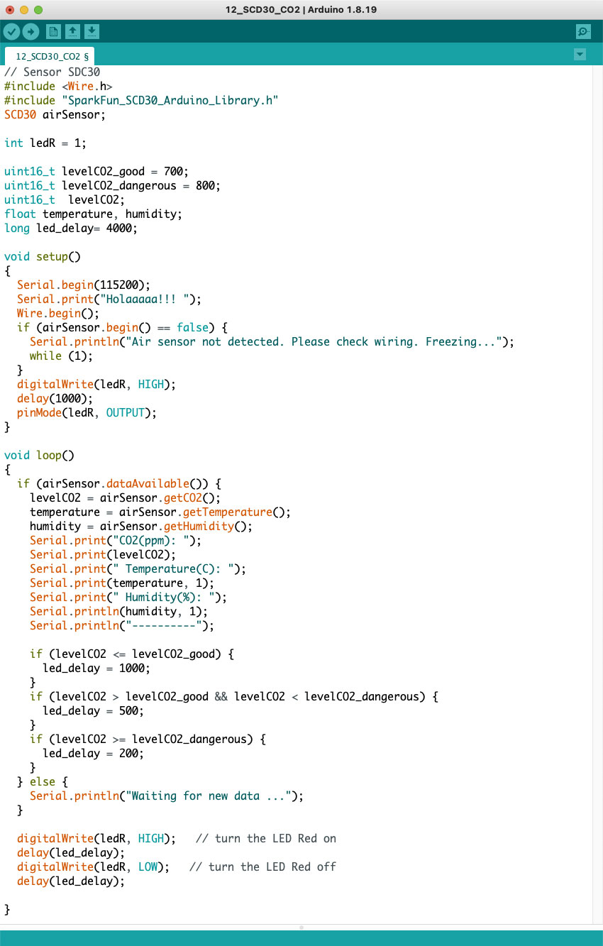
In this sketch using the SCD30 sensor and the led on the pcb, we warn of possible CO2 contamination in the room.
We take as quality range values less than 700 ppm, average quality from 700 to 800 ppm and for levels greater than 800 ppm poor quality. Depending on the quality, I blink the led more or less quickly.
And we make the observation of the data and how they vary once we ventilate the room.
After 4 hours windows closed, bad quality, more than 800 ppm.
After 10 min windows open, air quality begins to drop to average levels, more than 700 ppm and less than 800ppm.
After 30 min windows open, quality, less than 700 ppm.
RC Remote control
On June 18, the V Solar Regatta of Marine Instruments is held in Baiona (Pontevedra, Spain). Like other years, one of the most important things when designing cars or boats is the optimization of solar energy, the only way to power the prototype.
To do this, I am designing an automatic power management control system using a microcontroller.
On the one hand, I read the voltage and power consumed by the boat, and I check to be at the best value throughout the regatta.
The station I have is a multiprotocol Radiomaster TX16S with the OpenTX open system with the receptor R168.
Using an INA219 I read these values directly from the solar panel and the consumption by I2C. Through a radio control receiver, read if the control is in manual or automatic mode, and in automatic mode, the microcontroller manages the maximum speed of the boat that it can have at that moment based on the amount of solar energy that have available.
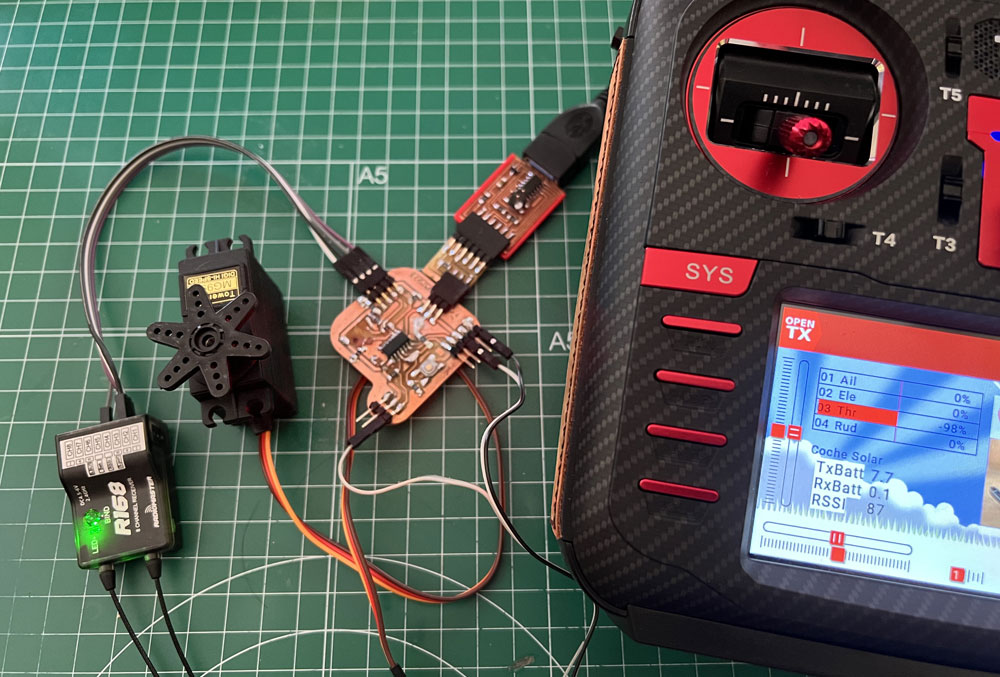
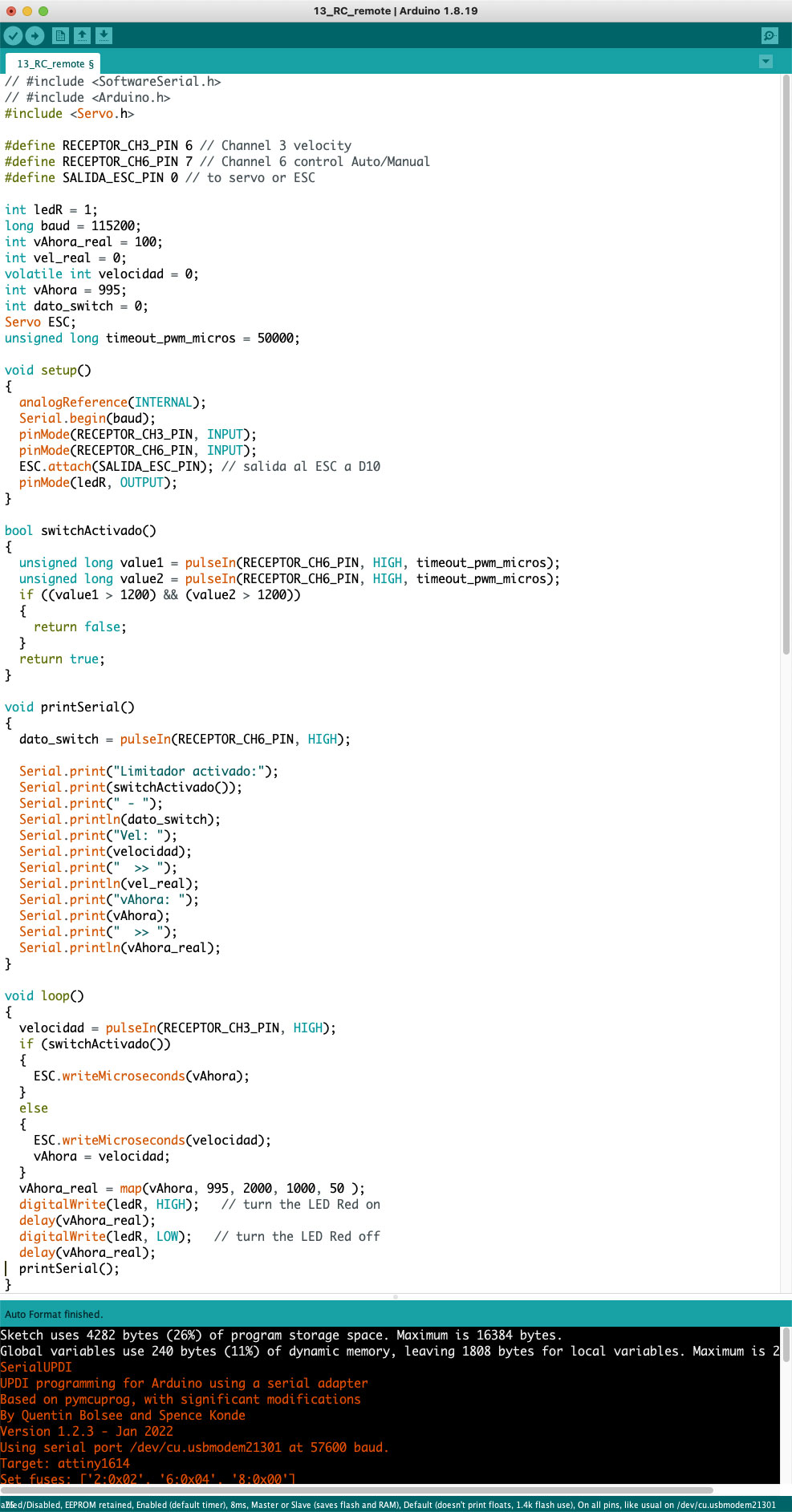
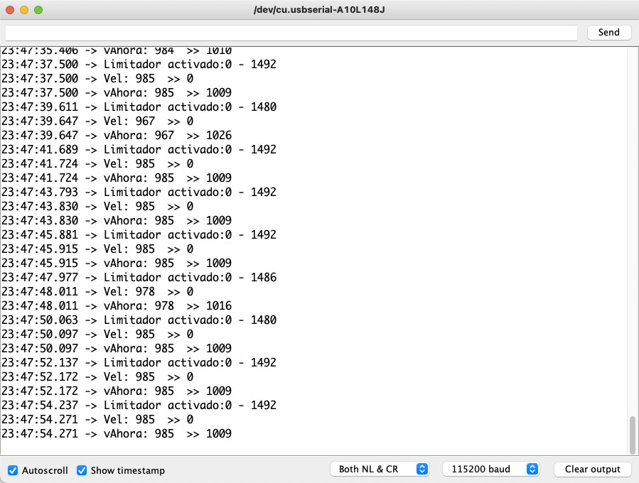
In this sketch I have started the design of the receiver’s two-channel reading system, and through a serial monitor, I visualize those parameters.
Subsequently, I make the led blink depending on the speed and move a servo (later it will be the ESC).
Downloads
- DS18B20 datasheet (.pdf)
- 08_Temperatura (.zip)
- 09_Temperatura1614 (.zip)
- MPU 6500 Datasheet (.pdf)
- 10_Temp_Aceleration (.zip)
- MS5611-01BA03-measurement Datasheet (.zip)
- 11_Temp-Baro (.zip)
- 10-11_Temp_GY86 (.zip).
- Sensirion CO2 datasheet (.pdf)
- 12_SCD30_CO2 (.zip)
- 12_SCD30_CO2 (.zip)
- INA219 datasheet (.pdf)
- 13_RC_remote (.zip)
Explore more like this
17 - Invention, Intellectual Property, and Income
This is the last week before I present the final project, I already have a slide and video proposal of my project.
16 - Applications and Implications
Propose a final project masterpiece that integrates the range of units covered, answering: