10 - Output devices
This week we have learned output devices, or how to interact with the outside from our devices.
Summary
This week we have learned output devices, or how to interact with the outside from our devices. Leds, screens, motors…
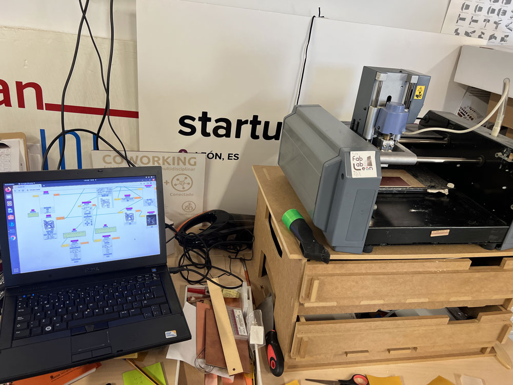
Also this week when I returned to the Fab Lab in León I tried another pcb manufacturing workflow, with Mods and the Roland Modela
Assigments
- individual assignment:
- add an output device to a microcontroller board you’ve designed,
- and program it to do something
- add an output device to a microcontroller board you’ve designed,
- group assignment:
- measure the power consumption of an output device
- measure the power consumption of an output device
Individual Assigment
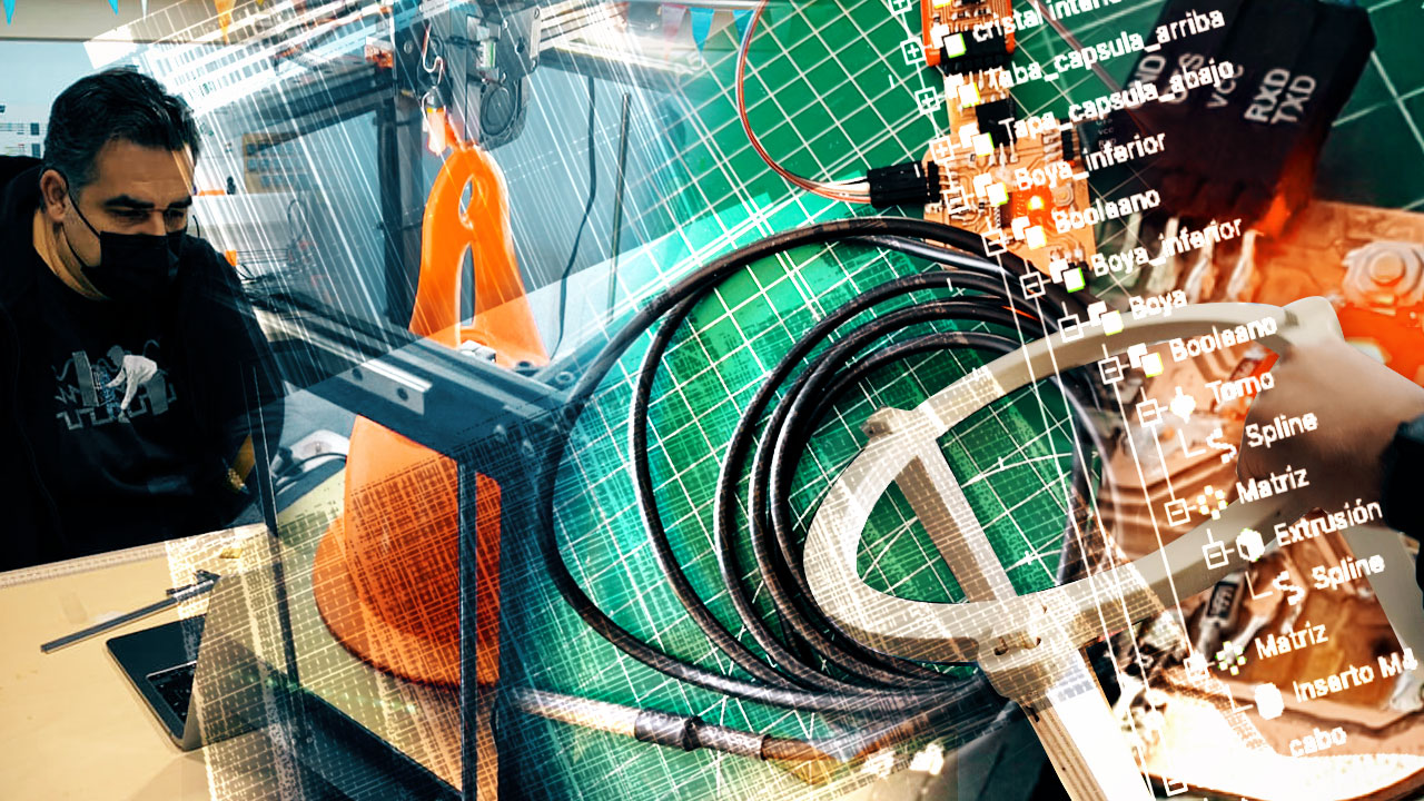
This week I have worked on output devices thinking about the final project, the needs of the connection project and thus take advantage of the practice to develop a pcb that will help me experiment in the coming weeks.
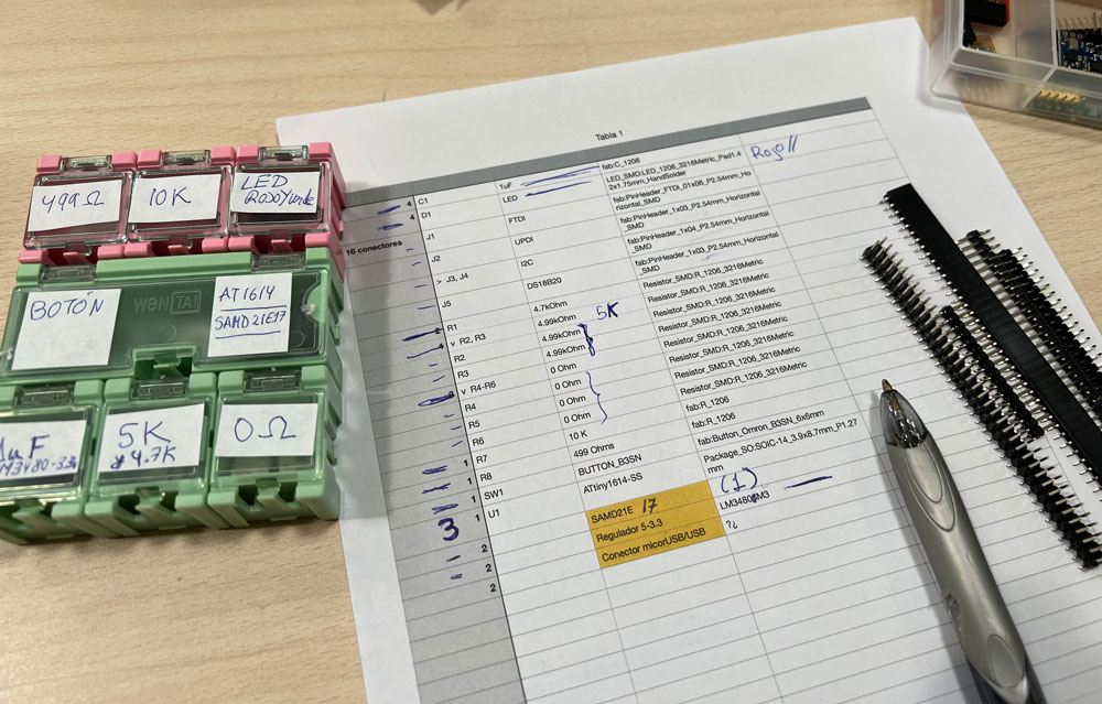
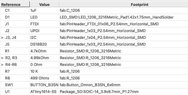
Initially one of the microcontrollers in which I have thought to base the project is the Attiny1614, so I decided to make a first pcb using it.
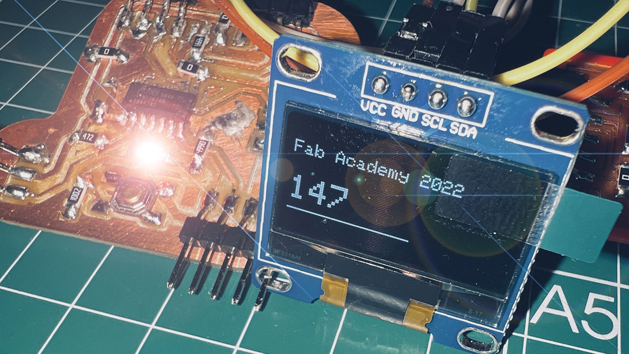
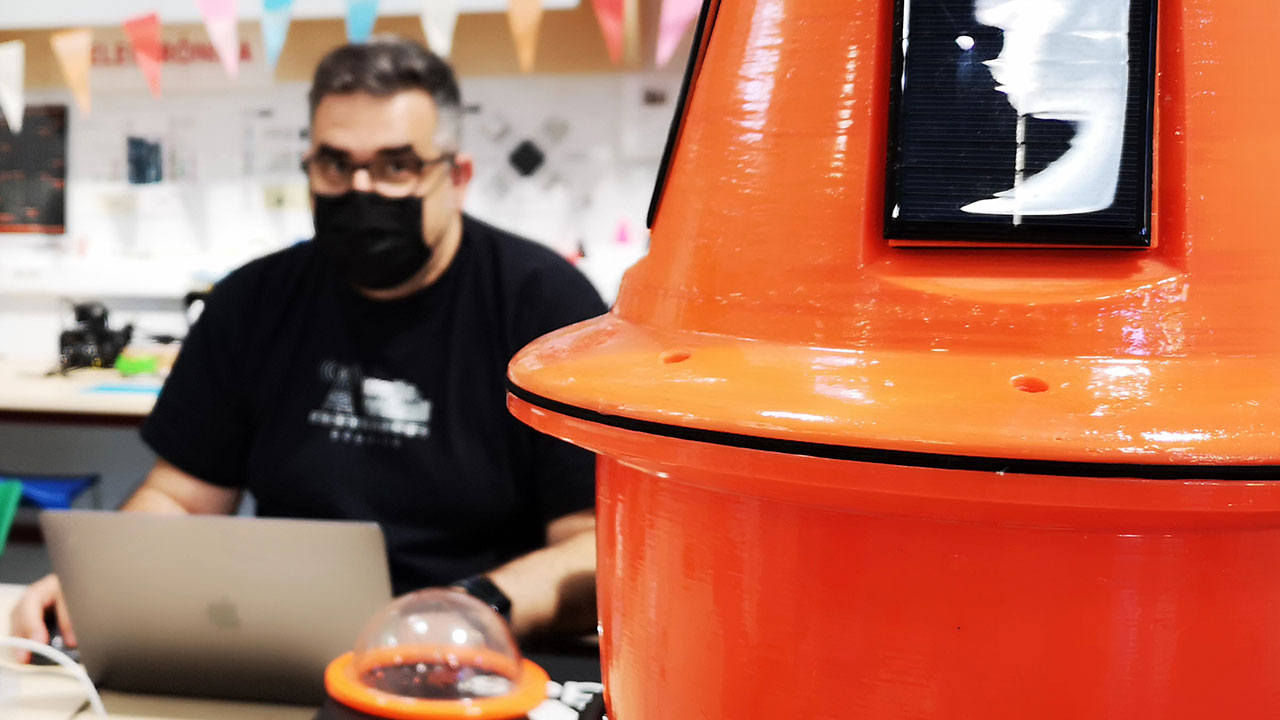
As an output device, in addition to an LED, my idea is to capture the data collected by the buoy in the lake on a screen, so I will use an OLED screen connected by I2C for this practice.
The I2C bus will serve me to connect both output devices, such as screens, or data input sensors (barometer, accelerometer, gyroscope…)
So I propose a board with I2C connectors, a led with a button, UPDI, FTDI and a digital connector to power the temperature sensor.
I do the development in KiCad, first with the schematic, defining all the possible ports as well as the necessary components. The Attiny1614 works at +5V so it will initially be the power supply that I will use.
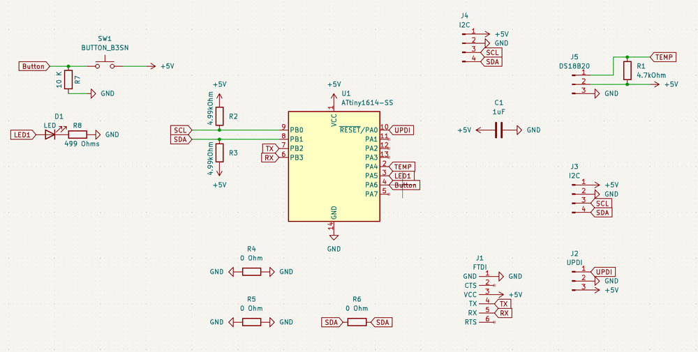
I try to optimize the pcb design, to use as few bridges as possible, but finally I have to use 3 0 ohm resistors.
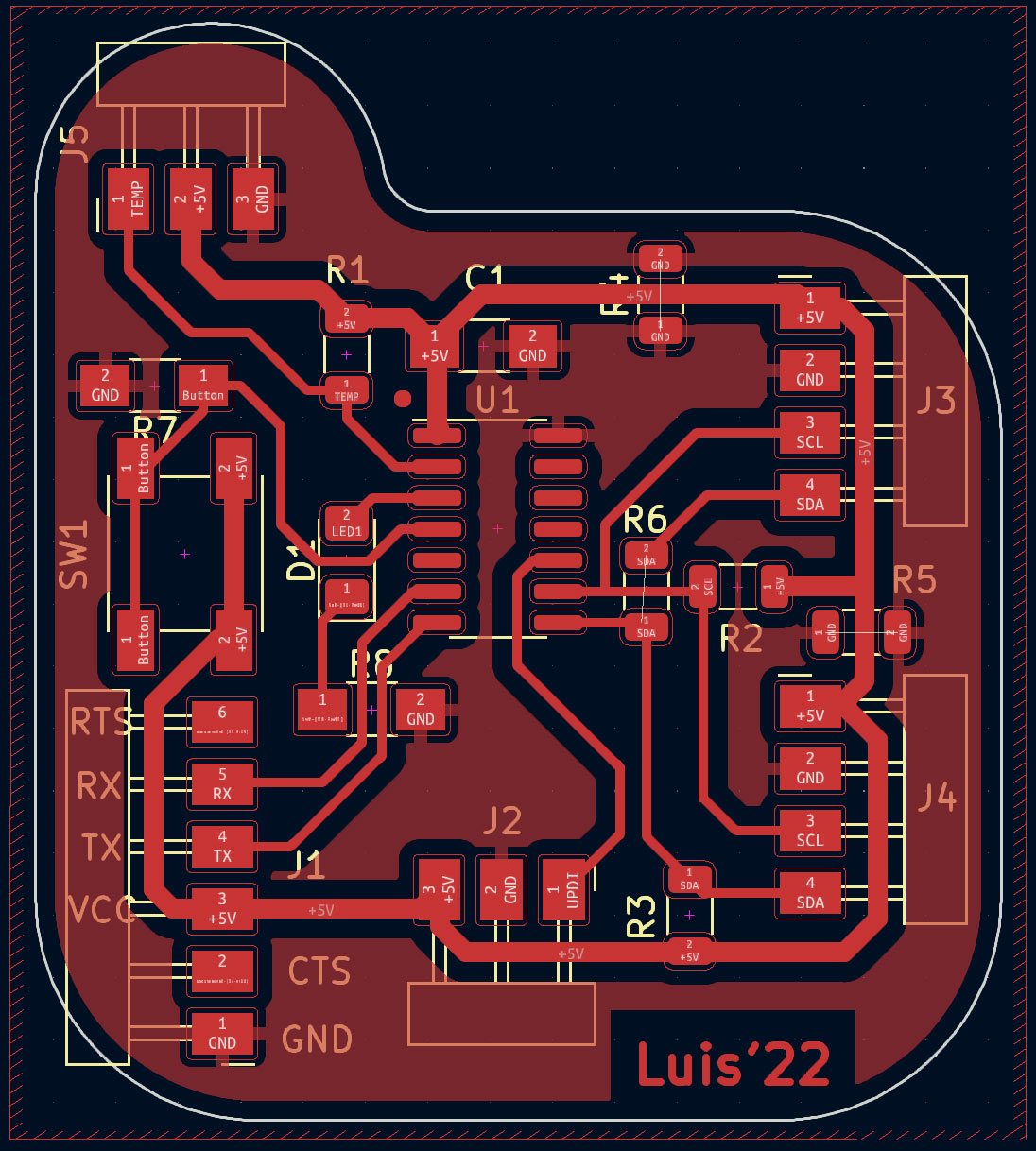
I already have the plate ready to mill. Tomorrow I’m going to León (1 Abril Friday), so I’ll take the opportunity to do it there, try to use the Mods and see how it works with the Roland machine.
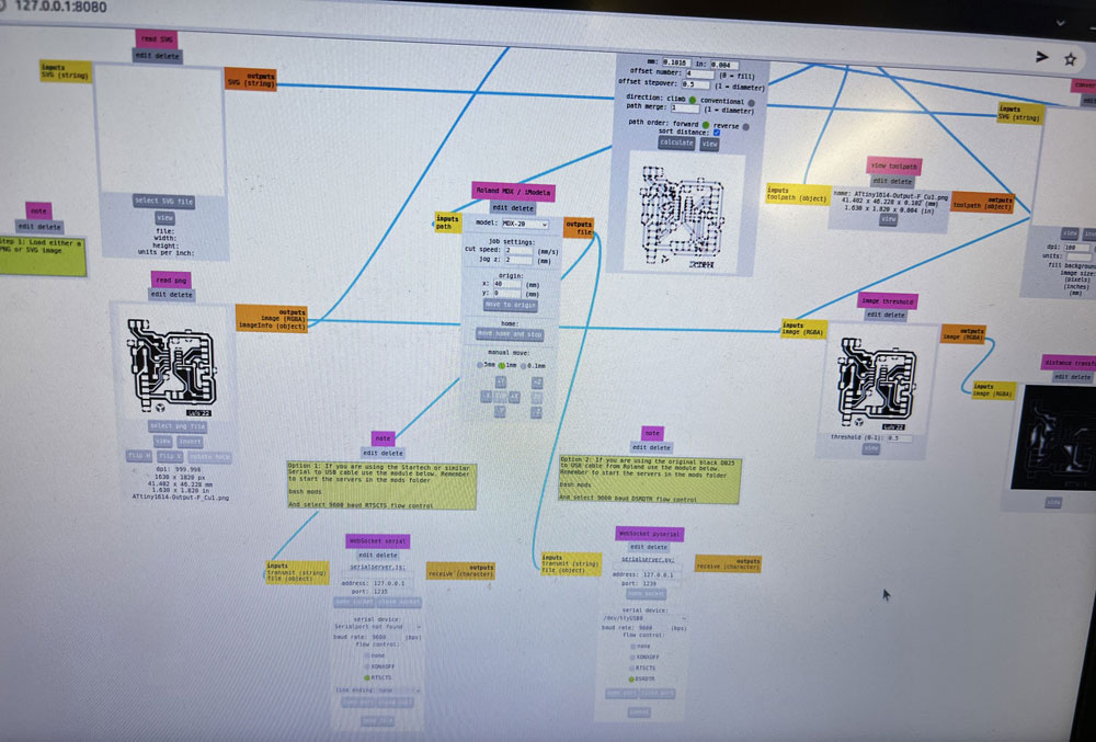
Mods and Roland
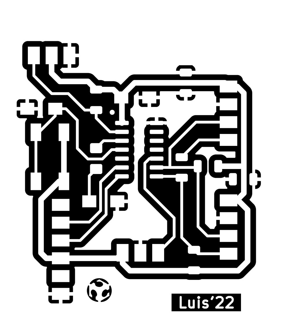
From KiCad I export the .svg that I open in photoshop, at 1000dpi, I invert the colors, before converting them to PNG.
They must be saved in “save as…” in PNG format, so that Photoshop does not reinterpret the dpi.
Once we have the PNGs, Adrián explains to me how the Roland Modela works and how to generate the gcodes in mods to use them.
In this case, from the Mods itself they are sent directly to the milling machine, via USB cable, without the need for additional software. Of course, they have a Linux installation, with the mods in executable mode to do the whole process directly.
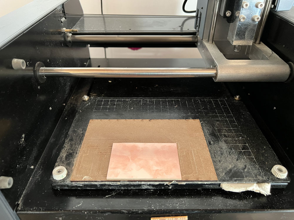
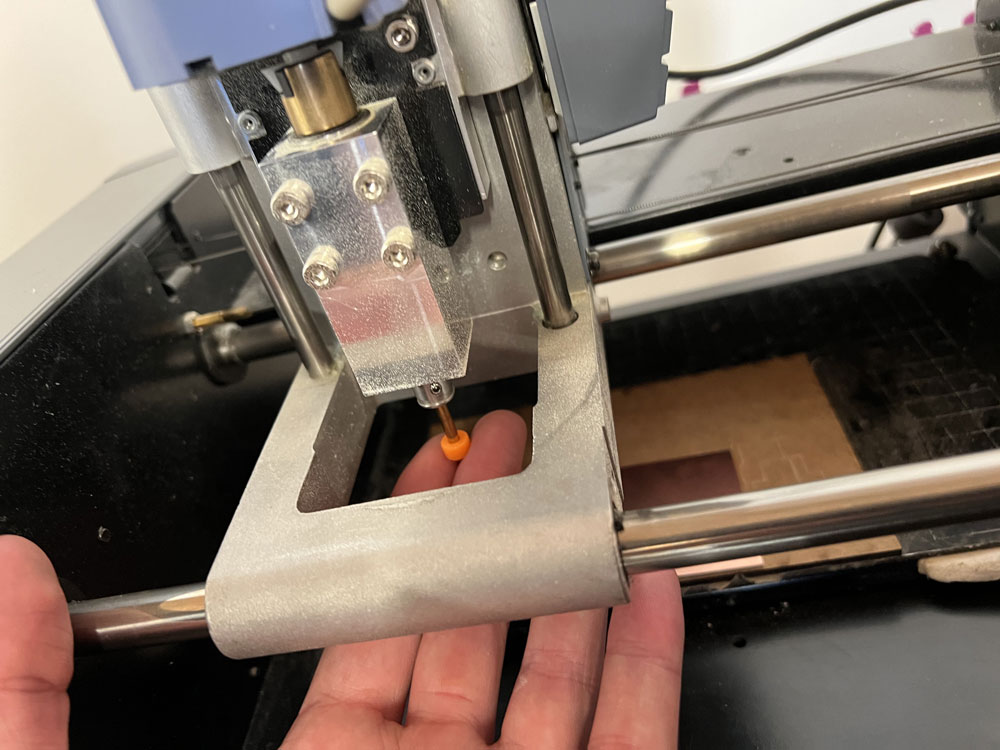
Before milling, we prepare the pcb, the mill and make the homming adjustments on the machine.
Once we have the hooming in x and done by means of a rule, we define what will be our 0.0 point in x and y at the time of milling.
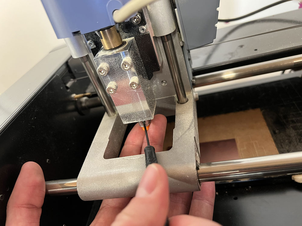
For the 0 in Z, we approach the mill without tightening it, we drop it on the pcb and once we have it located, we tighten it, and define our 0 for the Z axis.
We just configure the mods and if we see that everything is perfect, we start milling.
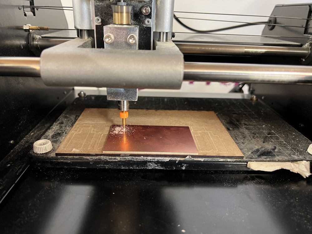
It seemed easier to me than with the Easel and the 3018, but I will try in the next PCBs that I make use what I learned today and transfer it to my machine.
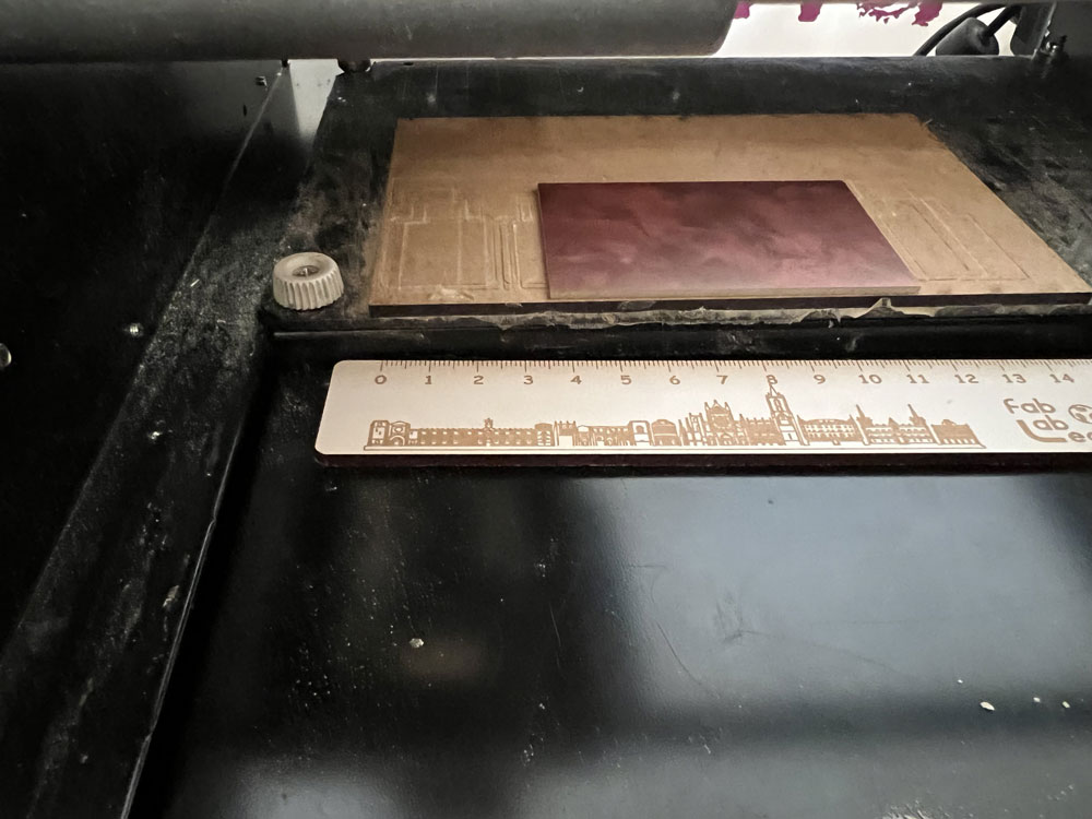
Also in less than 10 minutes I have the PCB done, with the Easel it was almost 1h40min…. I made many passes to get to all the areas of the pcb, tricking the program with a thinner mill.
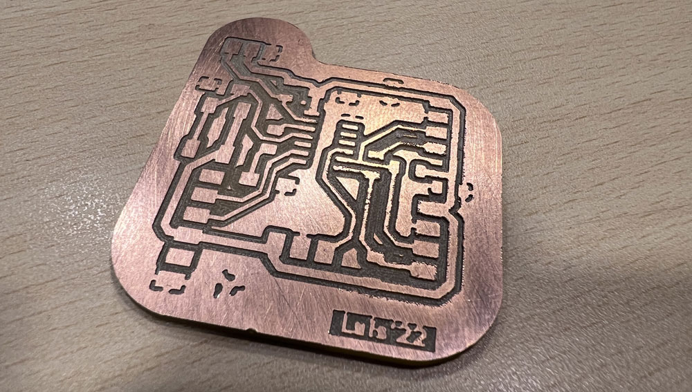
I checked that all the tracks had good continuity, and if necessary redo the pcb. The plate had to be perfect, otherwise once back I couldn’t do it again.
When I return to Vigo I will weld it and continue doing the practice.
In Fab Lab León they have given me all the necessary components to make the pcb.
Soldering
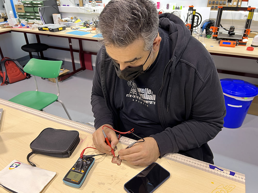
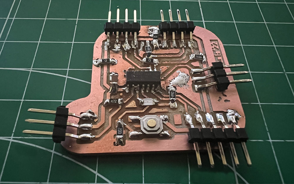
After identifying all the components I decide to solder the board, although I still have to practice more.
I have tried to do it with solder paste and hot air that Pablo Nuñez gave me, but it is not as easy as it seemed, so I have resorted to the usual tin and soldering iron.
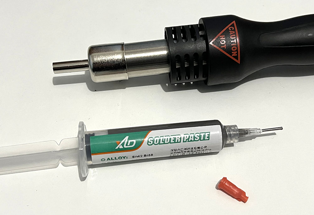
Surely on a manufactured pcb it will be easier than on milled boards.
Blink
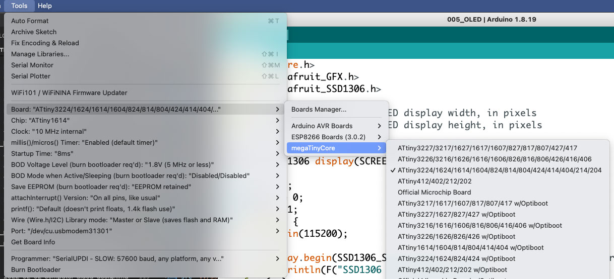
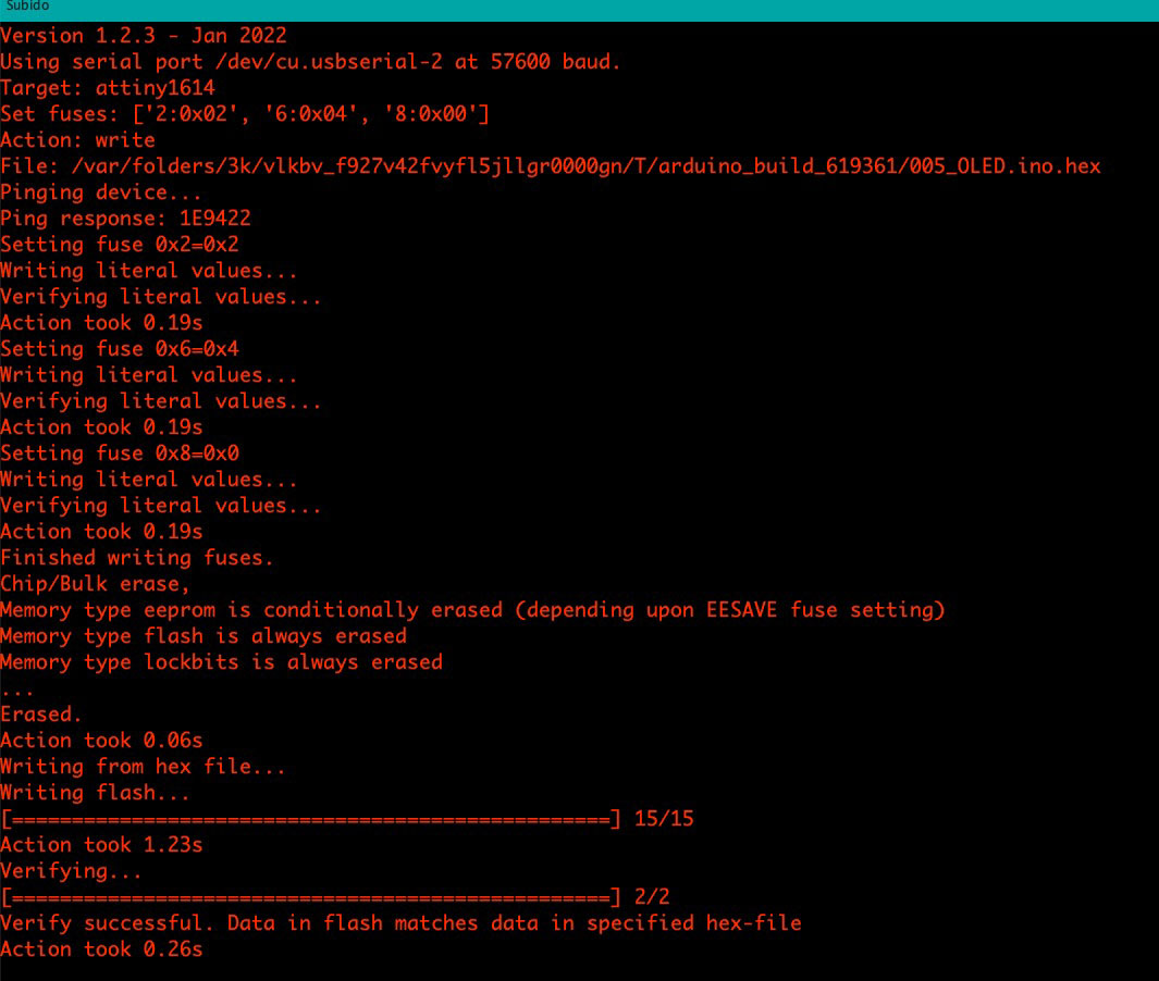
To connect the pcb to the Arduino and program it, I do it from “Tools>Board>megaTinyCore>” the ATtiny1614.
Once I finish soldering, I try to program it with a simple Blink, but the Arduino program always returns an error.
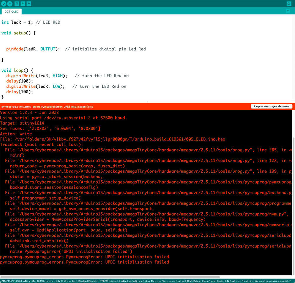
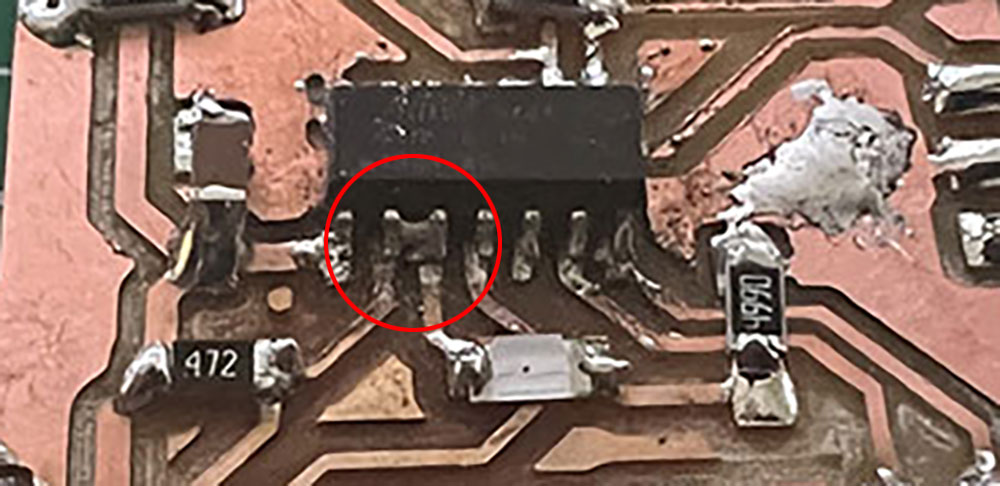
So I decide to recheck the welds and test continuity. It has been a long time of testing, until finally taking a picture of the PCB and looking at it carefully we see where the fault is.
OLED
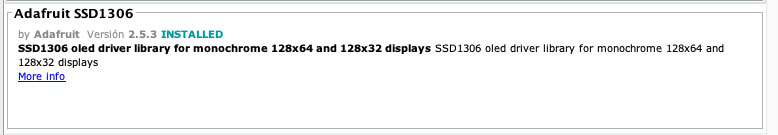
Now with the PCB working, I decide to implement the code that I had halfway through the OLED. To add it we must include the Adafruit SS1306 OLED libraries (link)
I implement a code in which a counter adds or subtracts a unit, from 0 to 255 and vice versa and with this variable I turn on a led little by little. On the screen I show the number, as well as draw a line as % intensity, since the total pixels is 128, I divide the current number by 2, to be able to show the total on the whole screen display.drawLine(0, 50, numero / 2, 50, SSD1306_WHITE);.
Sketch uses 14219 bytes (86%) of program storage space. Maximum is 16384 bytes. Global variables use 327 bytes (15%) of dynamic memory, leaving 1721 bytes for local variables. Maximum is 2048 bytes.
Once compiled the program almost occupies all the memory.
Group assignment
The link to Group Assignments of Fab Lab León is this
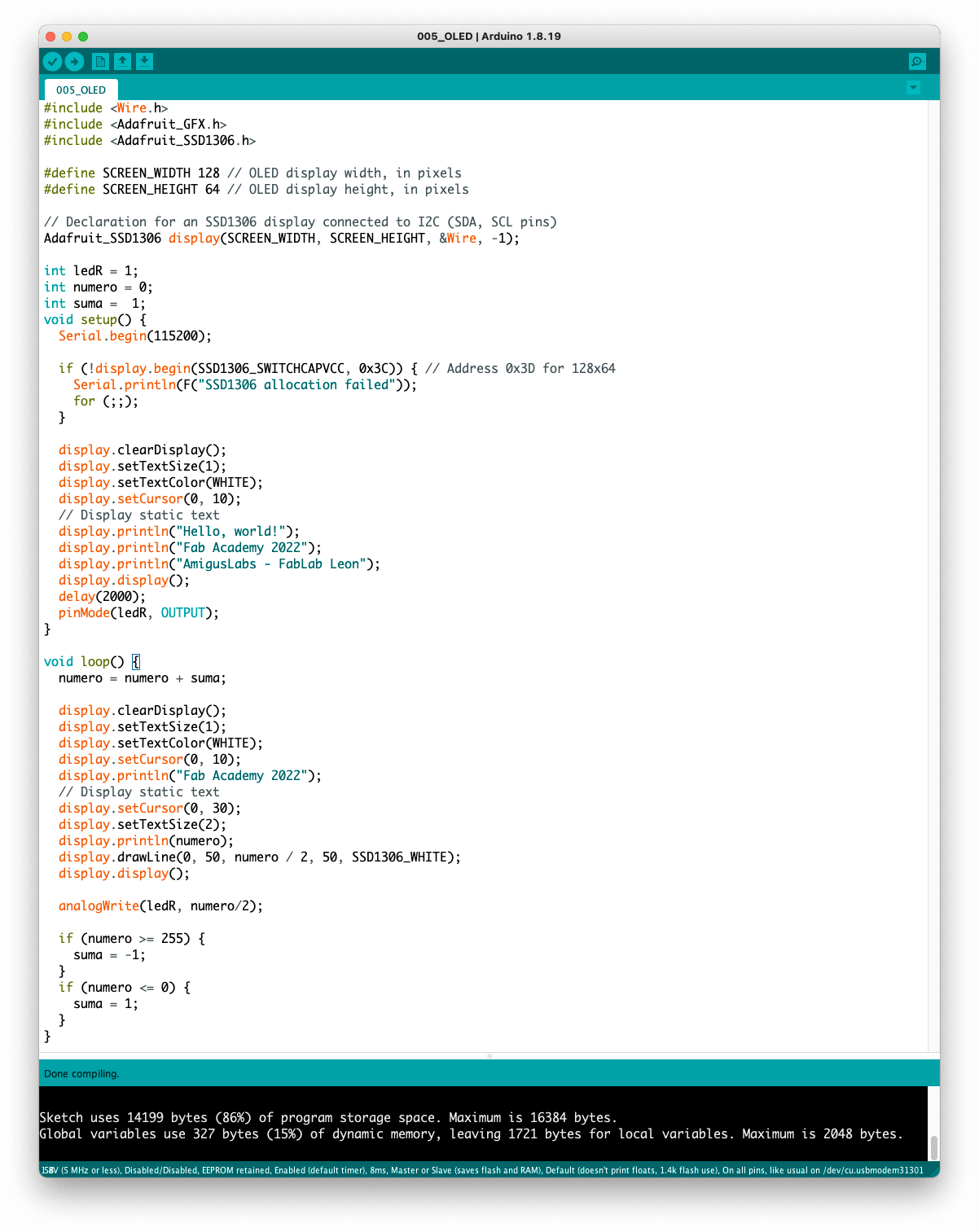
To measure the consumption of the board I connect the pcb to a laboratory power supply.
To measure the consumption of the board I connect the pcb to a laboratory power supply.
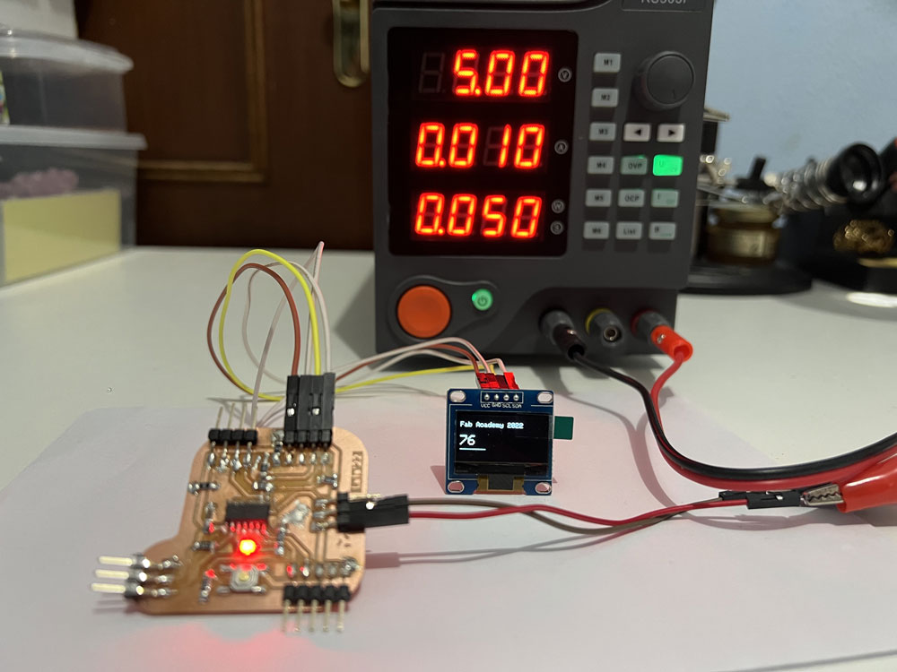
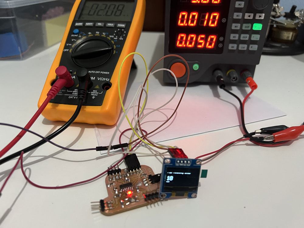
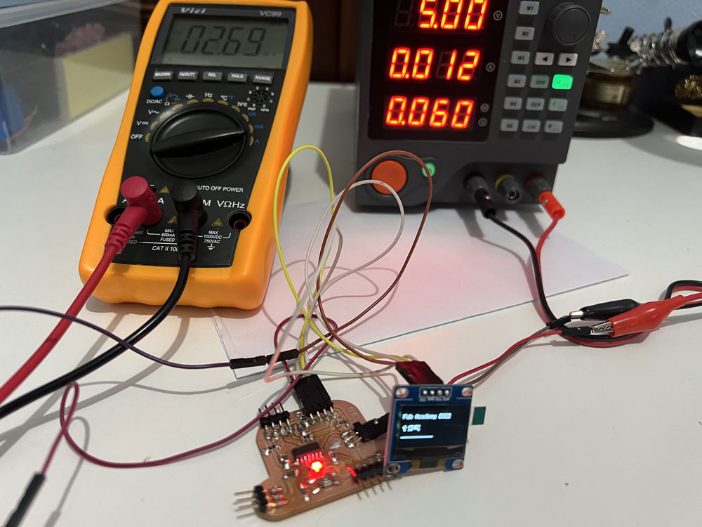
With the Led and the OLED powered at 5 Volts, the total consumption is 10 mA, 50 Watts. Depending on the number of pixels that are lit in the OLED and the intensity of the LED, the value is more or less high, reaching 12mA.
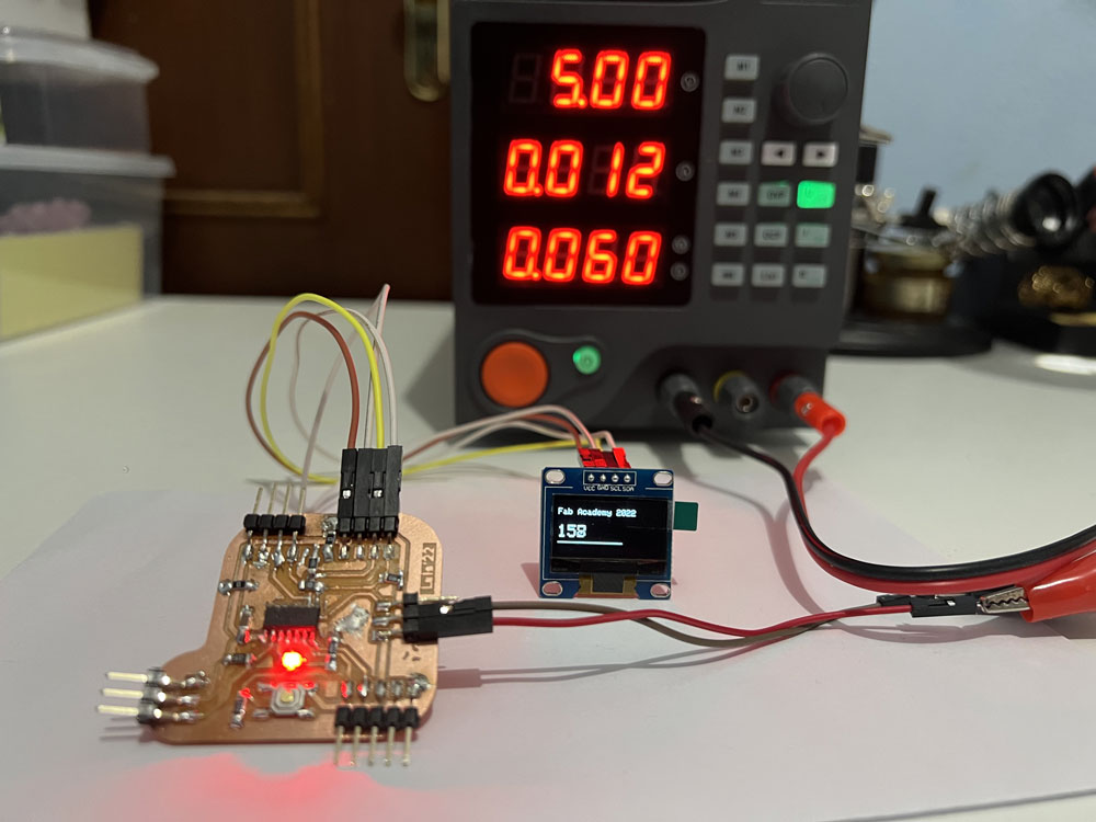
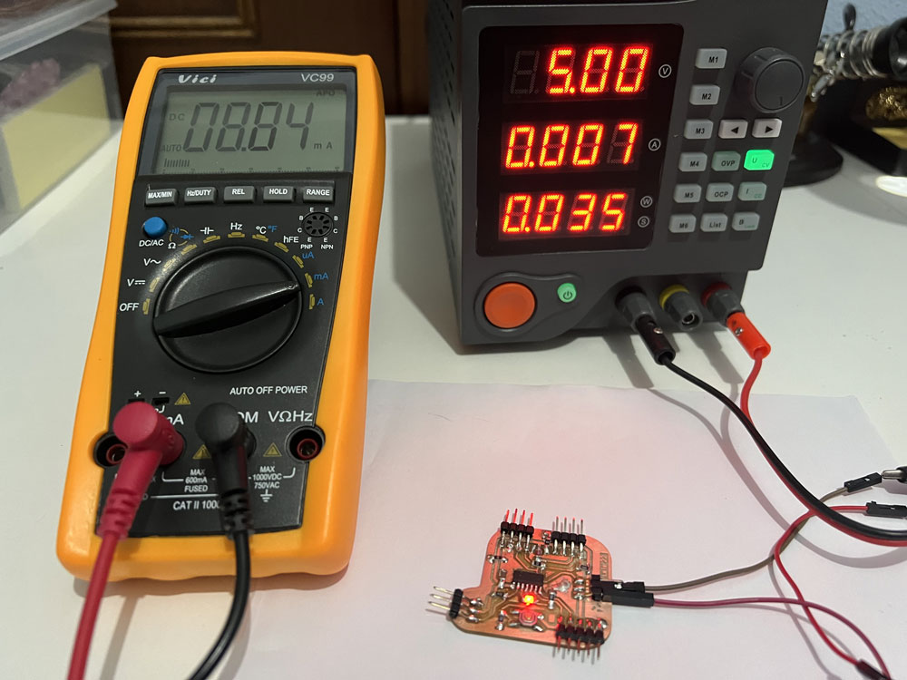
Only with the Led powered at 5 Volts, the total consumption is 7 mA, 35 Watts.
I make the same measurement with the multimeter and the value I get is 8.84 mA, 44 Watts.
I make measurements with different numbers of pixels on, so I plan to measure different percentages of pixels using a small Arduino program.
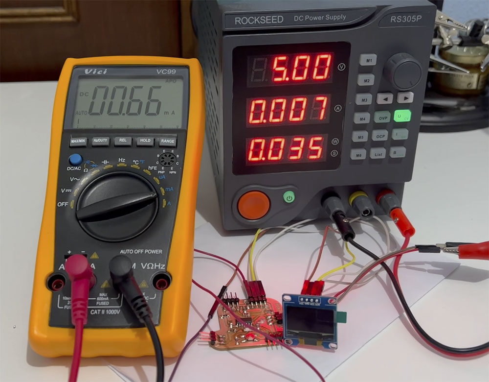
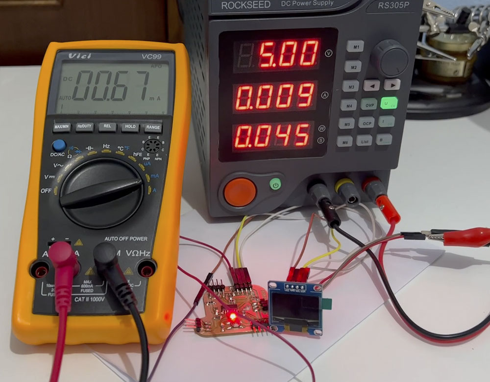
When the LED and OLED is Off, the total consumption is 7 mA, 35 Watts. The standby of OLED is 0.66mA.
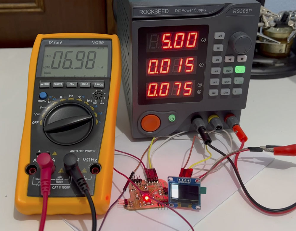
When the LED and OLED is on 25%, the total consumption is 15 mA, 75 Watts. OLED consumption is 6.98 mA.
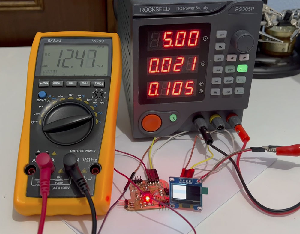
When the LED and OLED is on 50%, the total consumption is 21 mA, 105 Watts. OLED consumption is 12.47 mA.
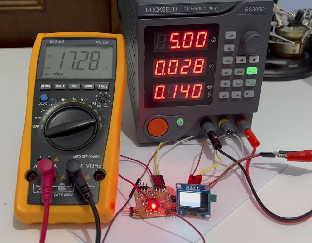
When the LED and OLED is on 75%, the total consumption is 28 mA, 140 Watts. OLED consumption is 17.28 mA.
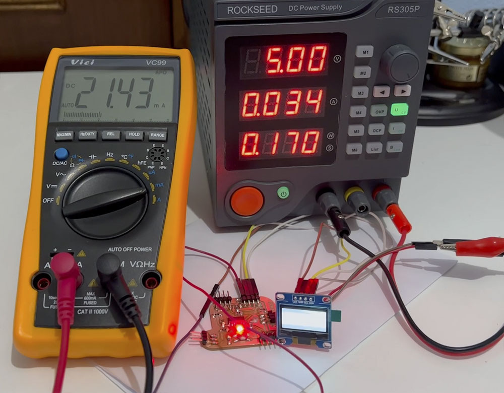
When the LED and OLED is on 100%, the total consumption is 34 mA, 170 Watts. OLED consumption is 21.43 mA.
When the LED is on 25% and OLED is in stand by, the total consumption is 9 mA, 45 Watts. The standby of OLED is 0.66mA. The LED consumtion is ~2 mA.
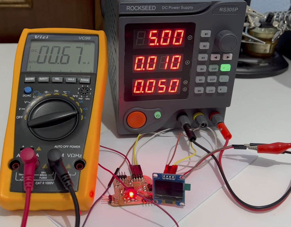
When the LED is on 50% and OLED is in stand by, the total consumption is 10 mA, 50 Watts. The standby of OLED is 0.66mA. The LED consumtion is ~3 mA.
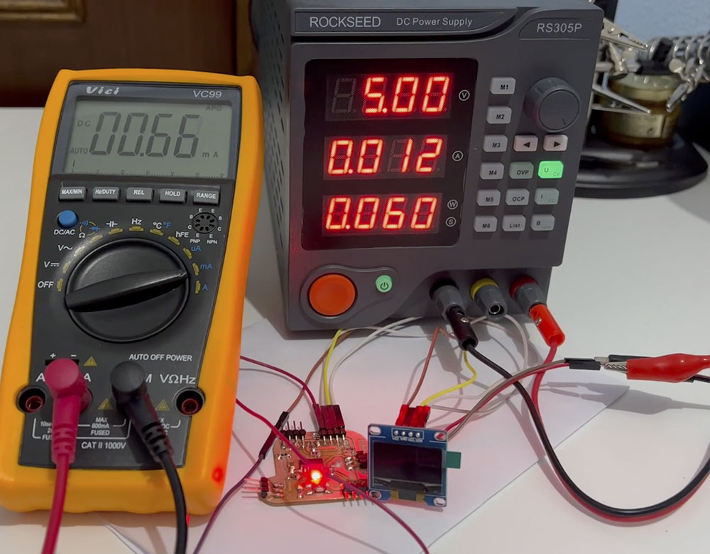
When the LED is on 75% and OLED is in stand by, the total consumption is 12 mA, 60 Watts. The standby of OLED is 0.66mA. The LED consumtion is ~4 mA.
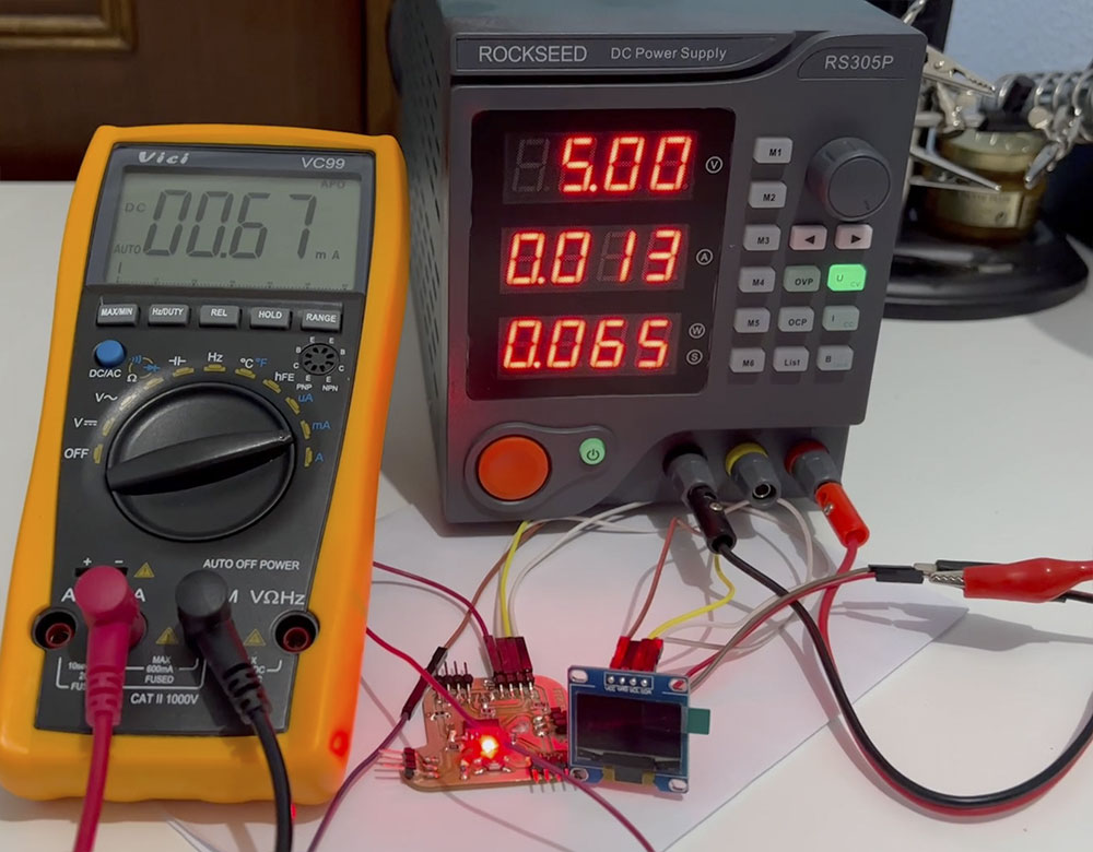
When the LED is on 100% and OLED is in stand by, the total consumption is 13 mA, 65 Watts. The standby of OLED is 0.66mA. The LED consumtion is ~6 mA.
Thinking about the electrical consumption of my final project, I must optimize very well what my components can consume, and how to optimize the battery and solar energy. Even between values, try to make a deep sleep of the microcontroller and try to lower those 7mA of consumption.
Downloads
Explore more like this
17 - Invention, Intellectual Property, and Income
This is the last week before I present the final project, I already have a slide and video proposal of my project.
16 - Applications and Implications
Propose a final project masterpiece that integrates the range of units covered, answering: