Leen Nijim
Assignment 15
Interface and Application Programming
Task
Our assignment this week was to create a user interface to interact with an input or an output device.
What You Need
Files to Download
Hero Shot
Group Assignment
For our group assignment, please click here.
Circuitry
For this week, using the board I made was not possible so far because we are still missing FTDI cables in the lab. So for the time being I used an Arduino Uno board and attached a potentiometer joystick to two analog input pins:
| Arduino Uno | Joystick |
|---|---|
| Pin 5V | Pin +5V |
| Pin GND | Pin GND |
| Pin A0 | Pin VRX |
| Pin A1 | Pin VRY |
User Interface Basics
In preparation for the week's task, our local instructor Marcello walked us through multiple examples of creating our very own first user interface application. For that I had to download and install the python environment Anaconda and the Tkinter and Pyserial libraries.
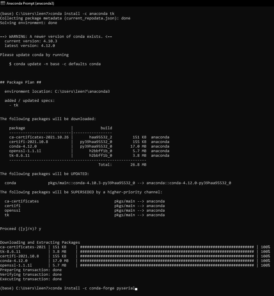
To install the libraries mentioned above, I opened the Anaconda Prompt and used first conda install -c anaconda tk:
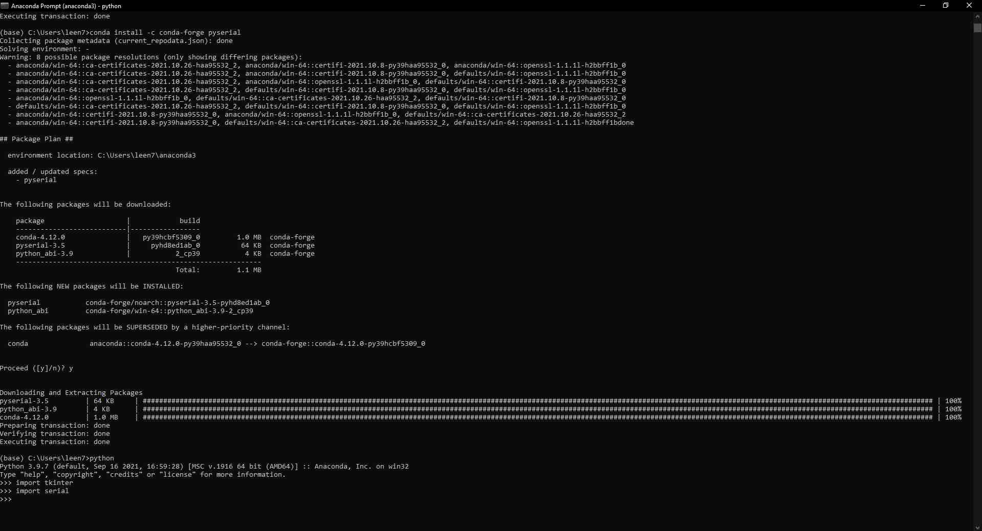
And then conda install -c conda-forge pyserial, and made sure both were installed properly by calling their instances within the prompt.
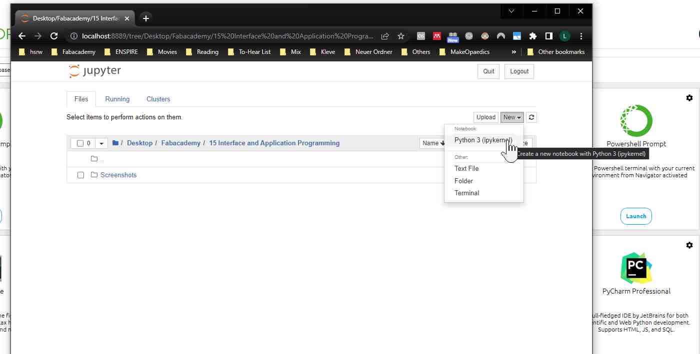
Then to start programming, I opened Anaconda Navigator and launched JupyterLab, then created a new Python 3 notebook in a local directory of my choice.
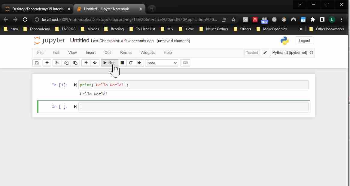
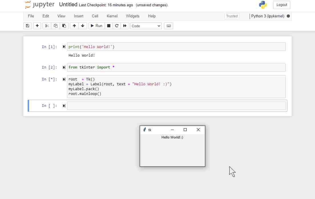
Here is my first python program print ('Hello World!')!
And here is the Hello World widget I made:
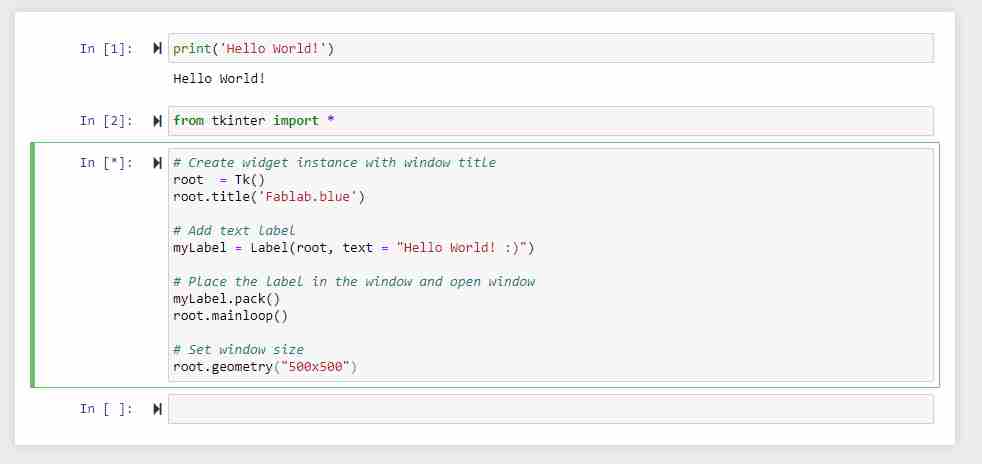
This was how I added a 'Fablab.blue' title to the widget:
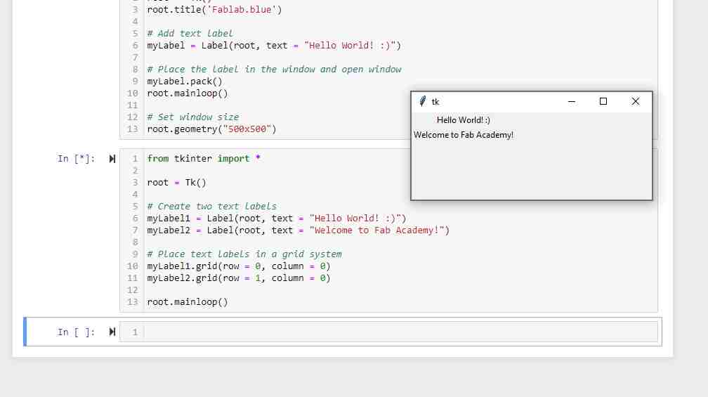
And here is how to add multiple labels:
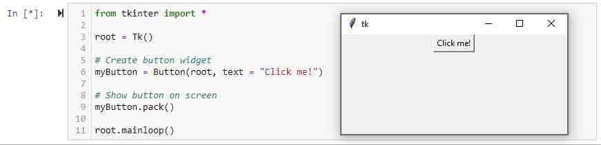
Then this is how I added a dummy button.
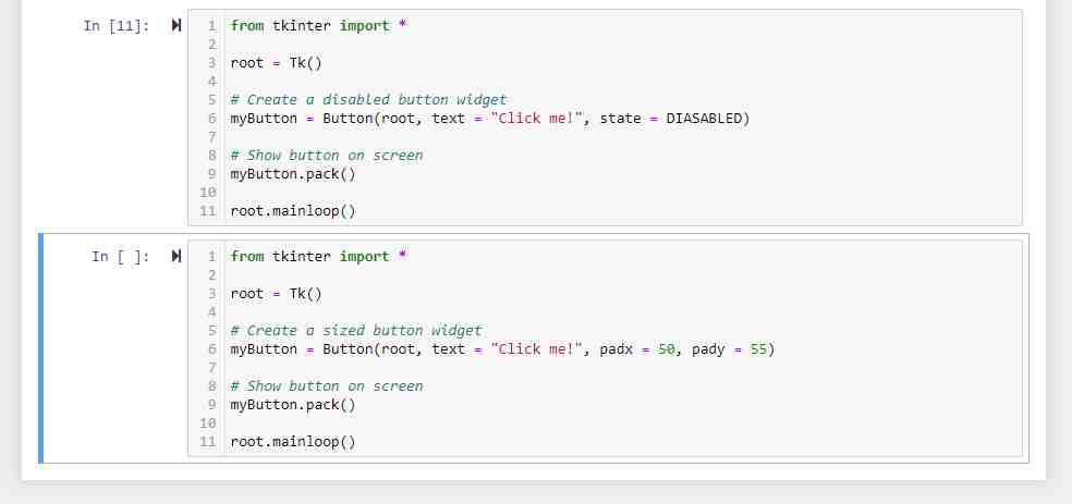
And this is how to add a disabled button, and how to set the button dimensions.
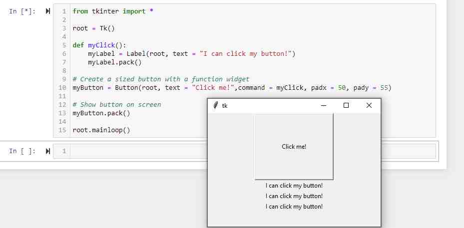
Here I programmed my button to write a label that confirms clicking it every time:
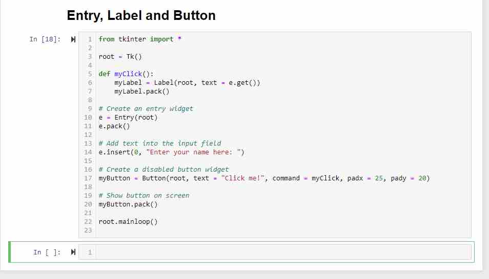
And this is how I created a widget with a data entry field.
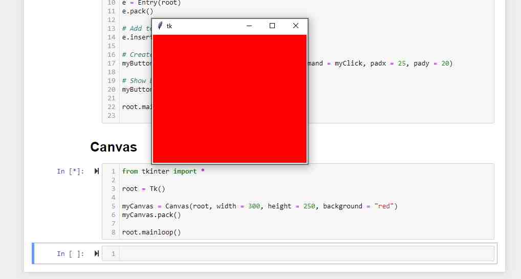
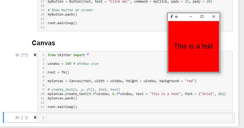
Here I created a canvas with a fill color.
And then added some formatted text in the red canvas.
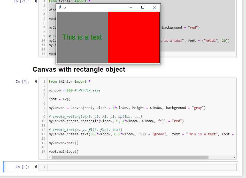
And then I added some green text and a red rectangle on a gray canvas.s
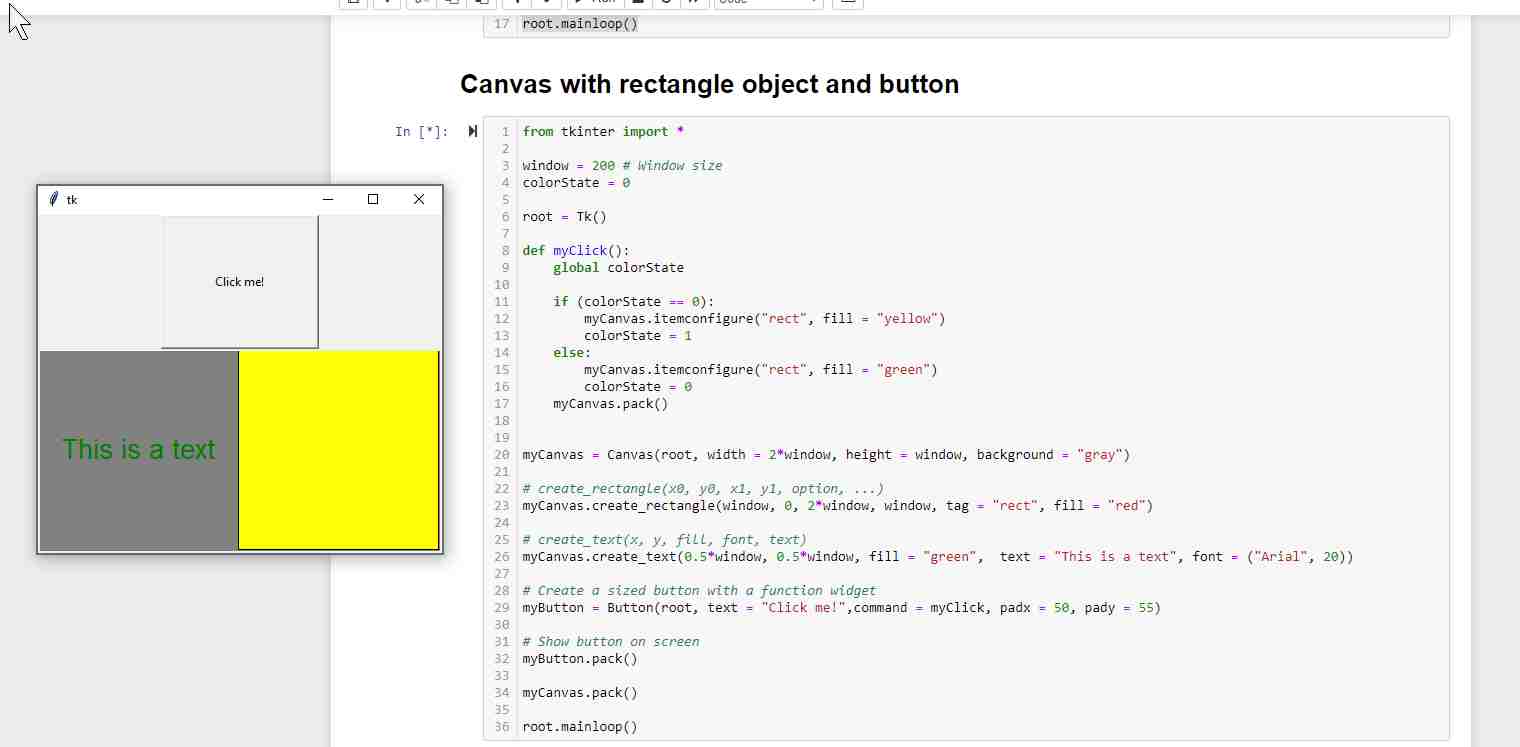
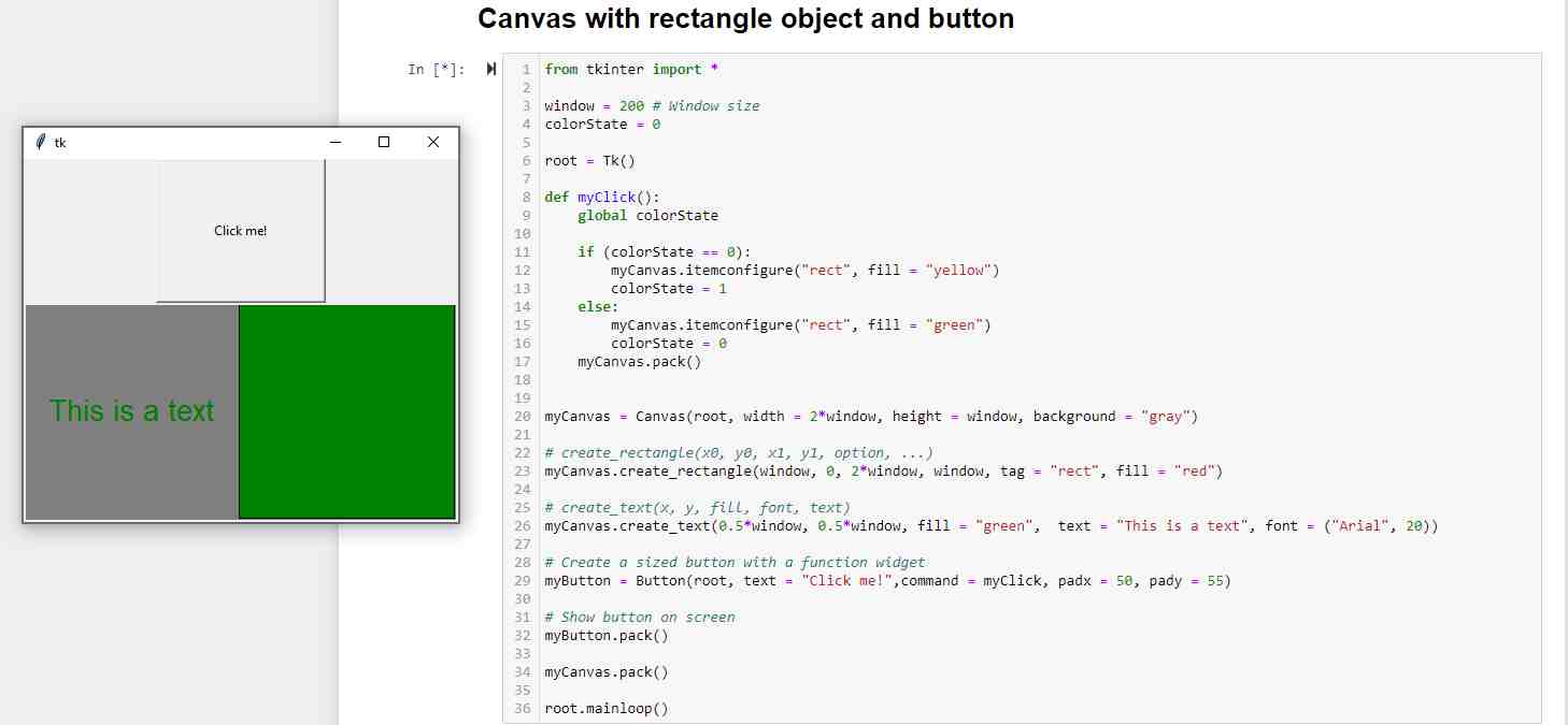
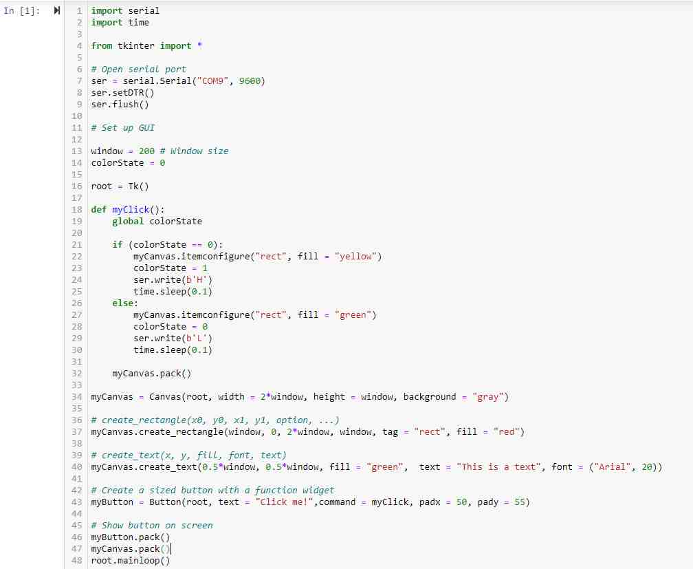
And here I combined the canvas, text, rectangle and button functions and created a widget that toggles the rectangle color between yellow and green whenever the 'Click me!' button is pushed.
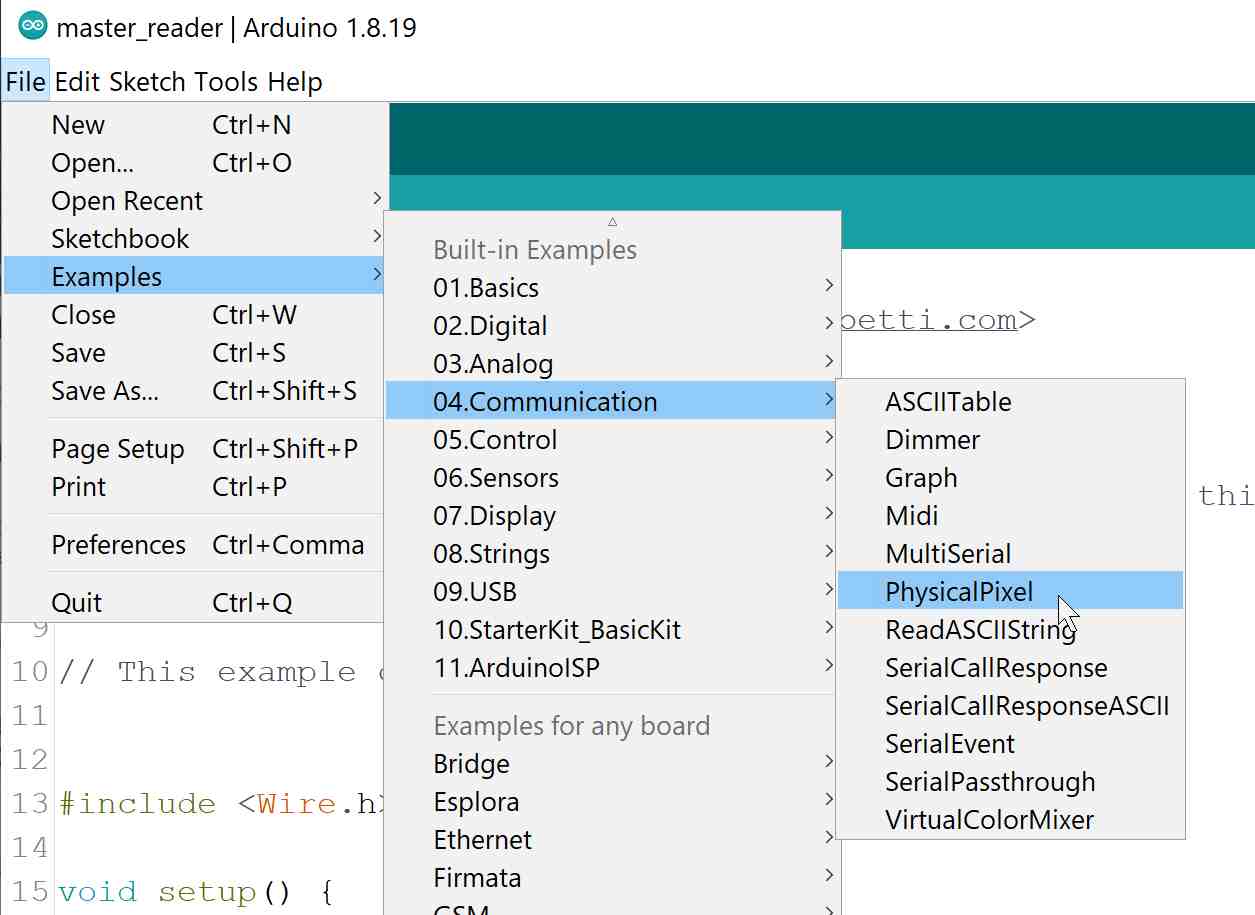
And for the last exercise, I made an interface that controlled the built-in LED on the arduino board via serial communication using the template arduino code File > Examples > Communication > PhysicalPixel.
My First Joystick User Interface
After I felt pretty confident about how to use Python and Tkinter, it was time that I started working on my own joystick controller interface. This needed two parts to be coded; one code for the microcontroller board which reads data from the physical potentiometer joystick and sends it via the serial bus, and the other for the user interface that interprets the joystick data and shows it on screen.
Programming the Microcontroller
I began by opening the arduino example Examples > Analog > AnalogInOutSerial and edited it to get the x and y potentiometer values from the joystick, and added the joystick's built-in button signal in the code for future use.
const int vRx = A0;  // Analog input pin that the potentiometer is attached to
const int vRy = A1; // Analog output pin that the LED is attached to
//const int button = 3;

int sensorValX = 0;        // value read from the pot serial monitor
int sensorValY = 0;
//int buttonVal = 0;

int outputValX = 0;
int outputValY = 0;
//char outputBut;

void setup() {
pinMode(vRx, INPUT);
pinMode(vRy, INPUT);
//  pinMode(button, INPUT);
}

void loop() {
// read the analog in value:
sensorValX = analogRead(vRx);
sensorValY = analogRead(vRy);
//  buttonVal = digitalRead(button);
// map it to the range of the analog out:
outputValX = map(sensorValX, 0, 1023, 5, 795);
outputValY = map(sensorValY, 0, 1023, 5, 795);
//  if(buttonVal){
//    outputBut = 'y';
//  }
//  else {outputBut = 'n';}

}
Programming the User Interface
I then started by recycling the last exercise code I did, and tweaked it so that it reads from the serial port instead of writes to it. Here I also have to give credit where credit is due, so here are some very helpful links I continuously went back to for guidance:
- Python tutorial.
- Python - Tkinter canvas tutorial.
- Marcello Tania's notes.
- Neil Gershenfeld's TLE493D vector magnetometer tiny412 hello-world example.
import serial
# import time
from tkinter import *
# Open serial port
ser = serial.Serial("COM8", 4800)
ser.setDTR()
ser.flush()
# Set up GUI
window = 800 # Window size
def idle(parent,myCanvas):
# message = xxxyyy
message = ser.readline()
message = str(message).replace("b", "").replace("\\r", "").replace("\\n", "").replace("'", "")
ser.flush()
xCoor = int(message[0:3])
yCoor = int(message[3:6])
# debugging:
#myLabel1 = Label(root, text = message)
#myLabel2 = Label(root, text = xCoor)
#myLabel3 = Label(root, text = yCoor)
#myLabel1.pack()
#myLabel2.pack()
#myLabel3.pack()
# create_rectangles(x0, y0, x1, y1, option, ...)
myCanvas.create_rectangle(0, 0, 0.5*window, 0.5*window, tag = "topLeft", fill = "gray")
myCanvas.create_rectangle(0.5*window, 0, window, 0.5*window, tag = "topRight", fill = "gray")
myCanvas.create_rectangle(0, 0.5*window, 0.5*window, window, tag = "botLeft", fill = "gray")
myCanvas.create_rectangle(0.5*window, 0.5*window, window, window, tag = "botRight", fill = "gray")
# canvas.create_oval(x0, y0, x1, y1, options)
myCanvas.create_oval(xCoor-4, yCoor-4, xCoor+4, yCoor+4, tag = "pointer", fill = "red")
myCanvas.update()
parent.after_idle(idle,parent,myCanvas)
root = Tk()
myCanvas = Canvas(root, width = window, height = window, background = "white")
myCanvas.pack()
root.after(100,idle,root,myCanvas)
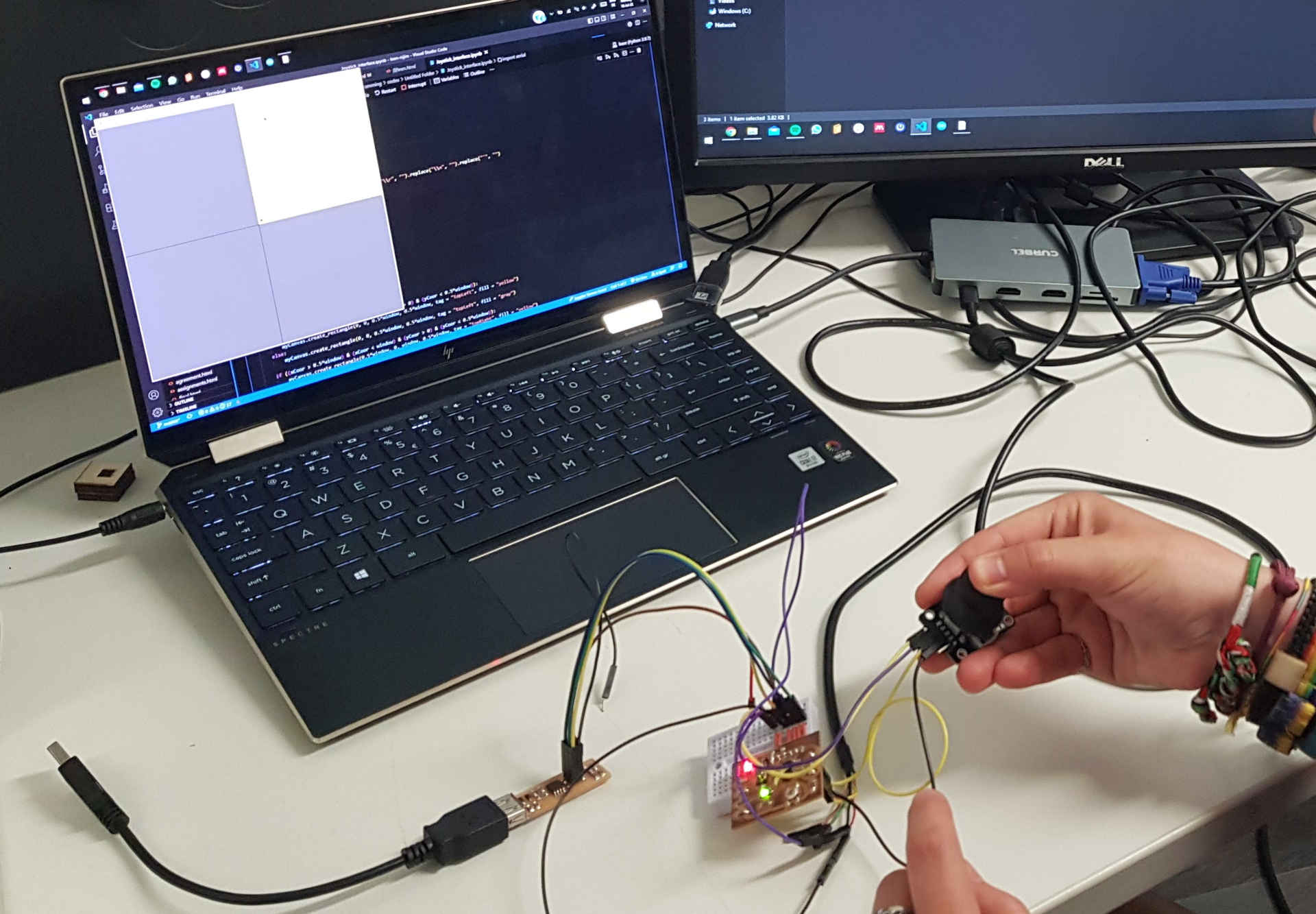
root.mainloop()After some debugging here and there, I was finally able to run my code and got some very satisfying results using an Arduino Uno.
Then I went back to the python code and made the four rectangles in the canvas light up whenever the circular cursor hovered over them. This just needed some additional if-else statements in the 'create_rectangles' section:
...

# create_rectangles(x0, y0, x1, y1, option, ...)
if ((xCoor > 0) & (xCoor < 0.5*window) & (yCoor > 0) & (yCoor < 0.5*window)):
	myCanvas.create_rectangle(0, 0, 0.5*window, 0.5*window, tag = "topLeft", fill = "yellow")
else:
	myCanvas.create_rectangle(0, 0, 0.5*window, 0.5*window, tag = "topLeft", fill = "gray")

if ((xCoor > 0.5*window) & (xCoor < window) & (yCoor > 0) & (yCoor < 0.5*window)):
	myCanvas.create_rectangle(0.5*window, 0, window, 0.5*window, tag = "topRight", fill = "yellow")
else:
	myCanvas.create_rectangle(0.5*window, 0, window, 0.5*window, tag = "topRight", fill = "gray")

if ((xCoor > 0) & (xCoor < 0.5*window) & (yCoor > 0.5*window) & (yCoor < window)):
	myCanvas.create_rectangle(0, 0.5*window, 0.5*window, window, tag = "botLeft", fill = "yellow")
else:
	myCanvas.create_rectangle(0, 0.5*window, 0.5*window, window, tag = "botLeft", fill = "gray")

if ((xCoor > 0.5*window) & (xCoor < window) & (yCoor > 0.5*window) & (yCoor < window)):
	myCanvas.create_rectangle(0.5*window, 0.5*window, window, window, tag = "botRight", fill = "yellow")
else:
	myCanvas.create_rectangle(0.5*window, 0.5*window, window, window, tag = "botRight", fill = "gray")

...
Wrapping It Up
Last thing I had to do was use my ATtiny44 hello board to read the joystick values and communicate them to the interface. But since the ATtiny44 microcontroller does not support hardware serial communication, I downloaded the SoftwareSerial Library and used it instead.
Here is the code I uploaded:
/*
Analog input, serial output

Reads an analog input pin, maps the result to a range from 0 to 100, and prints the results to the Serial Monitor.

created 29 Dec. 2008
modified 9 Apr 2012
by Tom Igoe

This example code is in the public domain.

https://www.arduino.cc/en/Tutorial/BuiltInExamples/AnalogInOutSerial

Modified by Leen Nijim
*/
#include

SoftwareSerial mySerial(PA2, PA3); // RX, TX

// These constants won't change. They're used to give names to the pins used:
const int vRx = PA0;  // Analog input pin that the potentiometer is attached to
const int vRy = PA1; // Analog output pin that the LED is attached to
//const int button = 3;

int sensorValX = 0;        // value read from the potserianl monitor
int sensorValY = 0;
//int buttonVal = 0;

int outputValX = 0;
int outputValY = 0;
//char outputBut;

void setup() {
// initialize serial communications at 9600 bps:
mySerial.begin(4800);

pinMode(vRx, INPUT);
pinMode(vRy, INPUT);
//  pinMode(button, INPUT);
}

void loop() {
// read the analog in value:
sensorValX = analogRead(vRx);
sensorValY = analogRead(vRy);
//  buttonVal = digitalRead(button);
// map it to the range of the analog out:
outputValX = map(sensorValX, 0, 1023, 5, 795);
outputValY = map(sensorValY, 0, 1023, 5, 795);
//  if(buttonVal){
//    outputBut = 'y';
//  }
//  else {outputBut = 'n';}
// change the analog out value:

if(outputValX<100){
	if(outputValX<10){
	mySerial.print("00");
	} else{
	mySerial.print('0');
	}
}
mySerial.print(outputValX);

if(outputValY<100){
	if(outputValY<10){
	mySerial.print("00");
	} else{
	mySerial.print('0');
	}
}
mySerial.print(outputValY);
mySerial.println();

//  Serial.print(outputBut);


// wait 2 milliseconds before the next loop for the analog-to-digital
// converter to settle after the last reading:
delay(100);
}
And here is my final result!