Final Project
Final Result

First Idea
This is my poitential final project named Love nose.
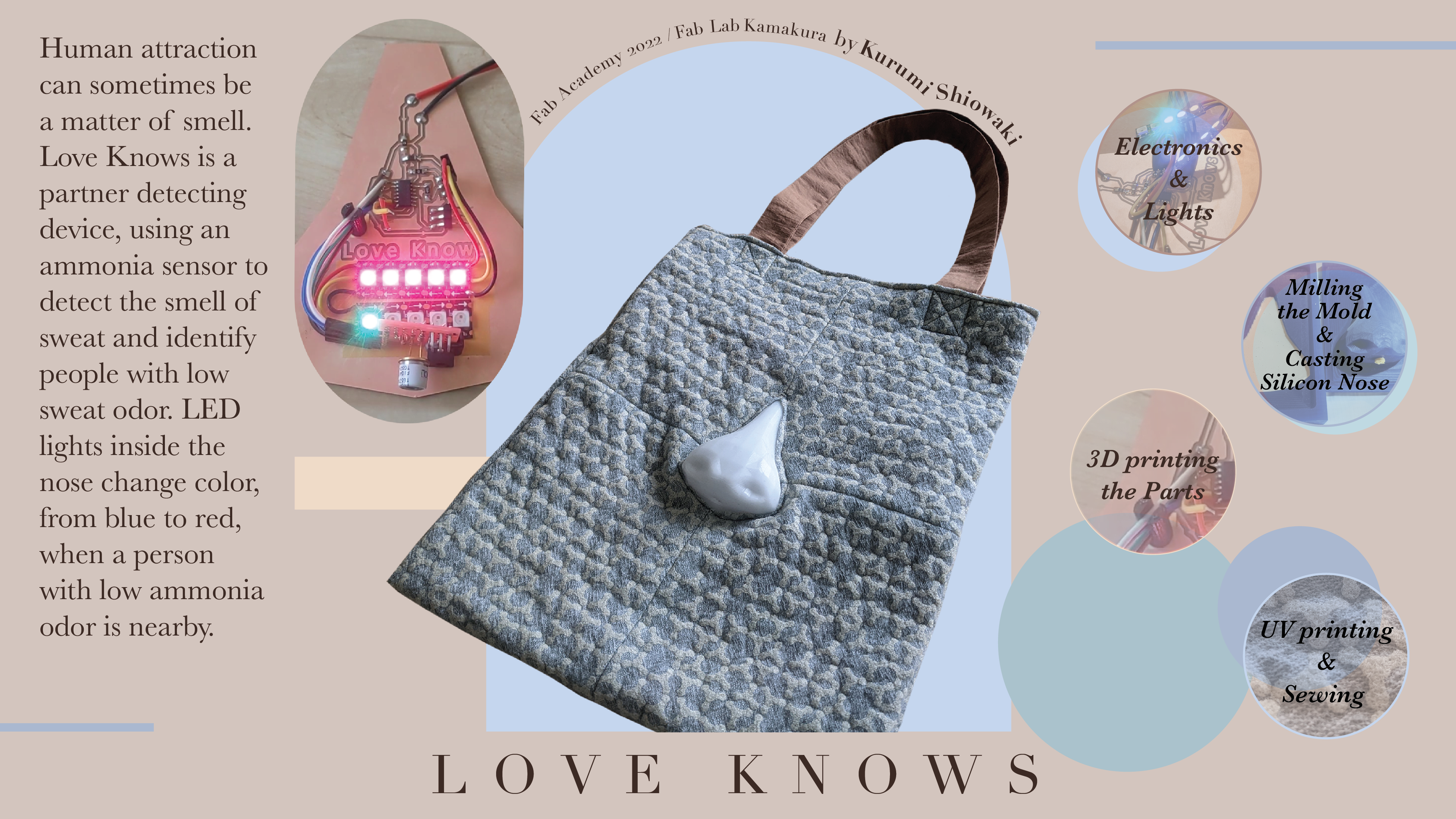
 The reason I thought of this project is because I am sensitive to smells. It is said that women, in particular, feel that a partner who has DNA that they do not have smells good (odorless). This allows them to leave behind a diversity of genes.
Therefore, I have heard that there is a Pheromone Party in London (odor matching party), and I thought that if I could find a partner who matches me on a DNA level, I would be able to live a happy life.
I think it is a very good device, especially for those who cannot find a good partner by themselves.
Research
In the town where I live now, the working-age population is decreasing year by year.

However, if you look at the number of singles and marriages, you will see that the number of people in their 30s decreases dramatically, but the possibility of meeting someone is still there.

If I can complete this device, I believe it will help alleviate the problem of declining birthrate and aging population in the town by increasing the number of couples and children.
Ultimately, I would like to be able to register some of your favorite smells and identify people who are close to those smells, but since odor sensors are still too expensive, I would like to use an ammonia sensor to create a device that can find people who have low ammonia levels in their sweat, in other words, people who don’t smell bad.
External Form
-
Fabric Bag with sewing machine (Origami shape memory on wool/ wool gauze with steam/ hot water)
-
Hard Silicone rubber for nose : Molding and Casting

Electronics
-
MCU : ATTiny412
-
sensors : Sndy Mq 137 (Ammonia sensor) 5V
-
power supply : 9V battery with voltage resulator
-
output devices : LED light (NeoPixel 5050 / Kingbright AAAF5050-MC-K12)
End Effector
-
Taking ammonia odor from Human with sensor. (Animal basically don’t have sweat gland )
-
Lights on when it is strong.
Programming
- Arduino
Taking a data of odor
void setup() {
 pinMode(3,OUTPUT);
 pinMode(4,OUTPUT);


 digitalWrite(3,LOW);
 digitalWrite(4,LOW);

 Serial.begin(9600);
}
void loop() {
 int val = 0;


 delay(237);


 digitalWrite(3,HIGH);
   delay(3);

   val = analogRead(A0);
   delay(2);
 digitalWrite(3,LOW);


 digitalWrite(4,HIGH);
   delay(8);
 digitalWrite(4,LOW);

 Serial.println(val);

}
Attach the number of odor sensor and light.
int redpin=3;
int greenpin=5;
int bluepin=6;

int val=0;
int ledVal=0;
int col;

void setup() {

  pinMode(redpin,OUTPUT);
  pinMode(greenpin,OUTPUT);
  pinMode(bluepin,OUTPUT);
  Serial.begin(9600);

}

void loop() {
  val=analogRead(0);
  ledVal=val/4;
  Serial.println(ledVal);

 if(ledVal<220){
  analogWrite(redpin,0);
  analogWrite(greenpin,0);
  analogWrite(bluepin,0);
 }
 else{
  for(col=255; col>0; col--)
 {
  analogWrite(redpin,col);
  analogWrite(greenpin,255-col);
  analogWrite(bluepin,128-col);
  Serial.println(col);
  delay(1);
 }
 for(col=0; col<255;col++)
 {
  analogWrite(redpin,col);
  analogWrite(greenpin,255-col);
  analogWrite(bluepin,128-col);
  Serial.println(col);
  delay(1);

 }
 }
 }
I made the light on light sensor with this programing.
Plan B

In the town where I live, the wind is strong, but there is no measurement data for the town.
I wanted to create a work that would help people notice the little things in the environment they live in and lead to bigger issues such as environmental problems.
In addition to measuring wind and collecting data, I would like to create a device that plays sound and a device that plays sound based on a person’s heart rate, and create a work that plays sound from two different materials.
Here is the example for playing sound with wind.

I believe that collaboration leads to knowing the other person deeply and taking an interest in them in order to know them.
Therefore, by listening to the sound that people make in collaboration with the wind, I aim to get people interested in the wind, which they usually do not pay attention to.
Project Tracking
02.27.2022
Researching for order the parts.
ATtiny 412 (8pin)

ATtiny 412 with Arduino

ATtiny 1624 (14pin)

ATtiny 1624 with Arduino

Mq137 (Gus sensor)
 Buying List
- Conductive Copper Foil Tape CU-18C Sheet type
- ATtiny 1624-SSU
- 9V battery
- Regulator LP2950L-5.0V 5V100mA
- Sndy Mq137 Gus sensor module
- Odor sensor TGS2450
- Transistor TTA008B 80V2A
- Resistor 300 ohm
- NeoPixel RGB TAPE LED 1m/ 60LED
- NeoPixel connector 10mm
- Wool gauze
- Sodium Chloride
- Cotton Linen
- Gel solution of human skin
- Pigment for human skin gel (skin color and white)
Links
03.20.2022
The project name has been decided as LOVE KNOWS
Sketch

Image photo

flow diagram

Some 2D and 3D sample here
05.01.2022
I created a new board on week 13 assignment. I can connect unexpecting sensors now.

Also tried to silicon nose on week 9.
I will try actual size(around 3 times bigger) of silicon nose.

I tried to ammonia sensor on week 12, but it didn’t go well. So I need more time to experiment the programming.

I will try fabric bag part on wild card week.
To Do list
(High priority)
- Taking ammonia ppm programing
- Molding and casting of actual size nose
- Last nose PCB with acrylic plate(add battery)
- Sewing the fabric bag
- Organizing inside of nose
- Organizing LED light tape
- LED tape animation
- Add sound and speaker
(Low priority)
05.25.2022
I started sketching what I need to do till finish this project.

And added the Vcc/ GND pats for my previous board design.
But I noticed I need to know the actual size of silicon nose. So I just leave it until I was going to Fab Lab Kamakura.
I had instructing and using middle size of CNC machine in Fab Lab Kamakura and Sky Lab on the 25th-30th May.

I made the Wax molding for silicon nose with OpenBuild C-Beam Machine with Dewalt 611 router spindle..
I created the G-code in Fusion360 CAM. Detail in week 9 documentation.
I need to download Open Build post processor.
I follow how to install from here.
And you can choose “OpenBuilds CNC” in Post.

And Wax setting is same on SRM-20.
 Setting the Origins.
You can use your phone as a controller!!
Open Wizards & Tools > Mobile Jog Widget.

Just Scan the QR code!!

Press here to set the Origins.

Set the Z origin too.

Update a G-code and start milling.
I tested by wood first.

And milling Wax.
Bottom was too fast at beginning. so melt and stuck the Wax…

20% low speed was Okay. Change the Feed 100% to 80%

In case, I chased the mill with small vacuum cleaner.

I tried casting when milling wax had done.
I used this “Human skin” silicon with pigment.

I wanted to make a hole for sensor. So design the parts on Fusion360 and add it with UV Resin.

it worked Okay.

It looks too watery. Let’s see what happens.

I left it 24 hours, and open it.
First of all, pigment was too much. I can’t see the light inside…><
And silicon was too sticky…
I think I should use hard silicon that Suzuki-san tried it in Group assignment on week 9.
Move on to Ammonia sensor board. I tried to MQ137 sensor first.
Code as follows:
/*
 * Program to measure the value of R0 for a know RL at fresh air condition
 * Program by: B.Aswinth Raj
 * Website: www.circuitdigest.com
 * Dated: 28-12-2017
 * Modified by: Kurumi Shiowaki
 * Dated: 26-4-2022
 */
//This program works best at a fresh air room with temperaure Temp: 20℃, Humidity: 65%, O2 concentration 21% and when the value of Rl is 47K

const int RL = 47 ; //define a constant variable called 'RL' with the value '47'

void setup()
{
  pinMode(7, INPUT);
  Serial.begin(9600); //initialize serial communication
  Serial.println("start");
}

void loop() {
  float analog_value = 0;
  float VRL;
  float Rs;
  float Ro;
  for(int test_cycle = 1 ; test_cycle <= 500 ; test_cycle++) //Read the analog output of the sensor for 200 times
  {
    analog_value = analog_value + analogRead(7); //add the values for 200
  }
  analog_value = analog_value/500.0; //Take average
  VRL = analog_value*(5.0/1023.0); //Convert analog value to voltage
  //RS = ((Vc/VRL)-1)*RL is the formulae we obtained from datasheet
  Rs = ((5.0/VRL)-1) * RL;
  //RS/RO is 3.6 as we obtained from graph of datasheet
  Ro = Rs/3.6;
  Serial.print("Ro at fresh air = ");
  Serial.println(Ro); //Display calculated Ro
  delay(1000); //delay of 1sec
But number seems not reliable and didn’t change that much…

So move on to TGS2450 sensor.
Sample circuit and code from here. Testing with Bread board first.

Got a number!!!!!
Design a universal board.
I chose this way because my instructor recommended it.
I can save the time for design and milling the board. Also I know it already works with breadboard, so I can make a board that is safe.


Soldering from back side

Create the connector of Neopixel tape.

Put in the silver part in Black socket.

It worked well

Make a ATtiny 1614 MCU board.
Design on KiCad


Trim in Illustrator as usual.

Milling and soldering


Check the Programing.
Code of Odor sensor
#define PIN_HEATER 6 // PB1
#define PIN_SENSOR 7 // PB0
#define PIN_OUTPUT 0 // PA4

void setup() {
 pinMode(PIN_HEATER,OUTPUT);
 pinMode(PIN_SENSOR,OUTPUT);
 pinMode(PIN_OUTPUT,INPUT);
 digitalWrite(PIN_HEATER,HIGH); // Heater Off
 digitalWrite(PIN_SENSOR,LOW); // Sensor Pullup Off

 Serial.begin(9600);
 Serial.println("start");
}
void loop() {
 int val=0;

 delay(237);
 digitalWrite(PIN_SENSOR,HIGH); // Sensor Pullup On
 delay(3);
 val = analogRead(PIN_OUTPUT); // Get Sensor Voltage
 delay(2);
 digitalWrite(PIN_SENSOR,LOW); // Sensor Pullup Off

 digitalWrite(PIN_HEATER,LOW); // Heater On
 delay(8);
 digitalWrite(PIN_HEATER,HIGH); // Heater Off
 Serial.println(val);
}
Code of Neopixel
#include <Adafruit_NeoPixel.h>
#include <avr/power.h>

#define NUM_LEDS 10

#define DATA_PIN 10

Adafruit_NeoPixel pixels = Adafruit_NeoPixel(NUM_LEDS, DATA_PIN, NEO_GRB + NEO_KHZ800);

void setup() {
    pixels.begin();
    Serial.begin(9600);
    Serial.println("start");

    pixels.setBrightness(100);
}

void loop() {
  for (int i=0; i<NUM_LEDS; i++){

    pixels.setPixelColor(i, pixels.Color(random(0, 255), random(0, 255), random(0, 255)));
    pixels.show();
    delay(100);
    pixels.setPixelColor(i, pixels.Color(random(0, 64), random(0, 64), random(0, 64)));
    pixels.show();
  }
}
Combining both code as follows;
#define PIN_HEATER 6 // PB1
#define PIN_SENSOR 7 // PB0
#define PIN_OUTPUT 0 // PA4

#include <Adafruit_NeoPixel.h>
#include <avr/power.h>

#define NUM_LEDS 10

#define DATA_PIN 10

Adafruit_NeoPixel pixels = Adafruit_NeoPixel(NUM_LEDS, DATA_PIN, NEO_GRB + NEO_KHZ800);

void setup() {
    pinMode(PIN_HEATER,OUTPUT);
    pinMode(PIN_SENSOR,OUTPUT);
    pinMode(PIN_OUTPUT,INPUT);
    digitalWrite(PIN_HEATER,HIGH); // Heater Off
    digitalWrite(PIN_SENSOR,LOW); // Sensor Pullup Off

    pixels.begin();
    Serial.begin(9600);
    Serial.println("start");

    pixels.setBrightness(100);// brightness Highest 255
}

void loop() {
  pixels.clear();

  int val=0;

 delay(237);
 digitalWrite(PIN_SENSOR,HIGH); // Sensor Pullup On
 delay(3);
 val = analogRead(PIN_OUTPUT); // Get Sensor Voltage
 delay(2);
 digitalWrite(PIN_SENSOR,LOW); // Sensor Pullup Off

 digitalWrite(PIN_HEATER,LOW); // Heater On
 delay(8);
 digitalWrite(PIN_HEATER,HIGH); // Heater Off
 Serial.println(val);

  if((val>600)){
   for (int i=0; i<NUM_LEDS; i++){

     pixels.setPixelColor(i, pixels.Color(0,0,00));
     pixels.show();

   }
  }

  if((val<600) && (val>300)){ // add a middle val
   for (int i=0; i<NUM_LEDS; i++){

     pixels.setPixelColor(i, pixels.Color(100,0,150));
     pixels.show();
     delay(100);
     pixels.setPixelColor(i, pixels.Color(0,50,50));
     pixels.show();
   }
  }

  if(val<300){ // add a high val
   for (int i=0; i<NUM_LEDS; i++){

     pixels.setPixelColor(i, pixels.Color(0,255,0));
     pixels.show();
     delay(100);
     pixels.setPixelColor(i, pixels.Color(50,0,50));
     pixels.show();
  }
 }
}
It work!!
05.31.2022
Back to Kuriyama.
And Making silicon nose with hard silicon.

It looks nice. But I created 2 more nose that are less white pigment.
Second one looks good for me.
Third one was bit too see-through inside.

Programing next.
Final color change to pink and blue
#define PIN_HEATER 6 // PB1
#define PIN_SENSOR 7 // PB0
#define PIN_OUTPUT 0 // PA4

#include <Adafruit_NeoPixel.h>
#include <avr/power.h>

#define NUM_LEDS 10

#define DATA_PIN 10

Adafruit_NeoPixel pixels = Adafruit_NeoPixel(NUM_LEDS, DATA_PIN, NEO_GRB + NEO_KHZ800);

void setup() {
    pinMode(PIN_HEATER,OUTPUT);
    pinMode(PIN_SENSOR,OUTPUT);
    pinMode(PIN_OUTPUT,INPUT);
    digitalWrite(PIN_HEATER,HIGH); // Heater Off
    digitalWrite(PIN_SENSOR,LOW); // Sensor Pullup Off

    pixels.begin();
    Serial.begin(9600);
    Serial.println("start");

    pixels.setBrightness(100);// brightness Highest 255
}

void loop() {
  pixels.clear();

  int val=0;

 delay(237);
 digitalWrite(PIN_SENSOR,HIGH); // Sensor Pullup On
 delay(3);
 val = analogRead(PIN_OUTPUT); // Get Sensor Voltage
 delay(2);
 digitalWrite(PIN_SENSOR,LOW); // Sensor Pullup Off

 digitalWrite(PIN_HEATER,LOW); // Heater On
 delay(8);
 digitalWrite(PIN_HEATER,HIGH); // Heater Off
 Serial.println(val);

  if((val>500)){
   for (int i=0; i<NUM_LEDS; i++){

     pixels.setPixelColor(i, pixels.Color(0,0,00));
     pixels.show();

   }
  }

  if((val<500) && (val>300)){ //middle val turn to Pink light
   for (int i=0
   ; i<NUM_LEDS; i++){

     pixels.setPixelColor(i, pixels.Color(0,150,50));
     pixels.show();
     delay(50);
     pixels.setPixelColor(i, pixels.Color(255,0,50));
     pixels.show();
   }
  }

  if(val<300){ // high val turn to Blue light
   for (int i=0; i<NUM_LEDS; i++){

     pixels.setPixelColor(i, pixels.Color(0,100,80));
     pixels.show();
     delay(100);
     pixels.setPixelColor(i, pixels.Color(00,50,255));
     pixels.show();
  }
 }
}
Create the wires organizing parts and sensor holder on 3D printer.

Work well.

Device part is all done!!

Sewing the snap button on silicon and glue to PCB.

It worked well.

Sewing the bag and check the nose stick nice.

Create the pocket inside of the zipper for battery box.

Also added the zipper for hiding everything.

All packed nicely.

Done!!!!!!!

Work great!!!!!

Let’s make a Video!!
Started to make a story board.

Filming

Friend of mine shooting the drone shots!!

Check the music in kibaco’s studio.

Editing and Animating on After Effects.

Also create a image board on Illustrator.

Upload the Video and Image as week17 assignment.
And Presentation!!!

Bill of Materials
MCU Board
- ATtiny 1614-SSNR 135yen
- Capacitor 25V 1μF 15yen
- Resistor 0 Ohm 10yen(2set)
- Resistor 499 Ohm 8yen
- Header pin 6pin 136yen
- WS2812B Pixel LED Strip 8mm 3535IC 274yen(10cm)
Ammonia Sensor Board
- Odor Sensor TGS2450 300yen
- Regulator LP2950L-5.0V 5V100mA 20yen
- Header pin 6pin 136yen
- Resistor 10K Ohm 22yen
- Resistor 1K Ohm 44yen(2set)
- Resistor 15 Ohm 17yen
- Resistor 10 Ohm 3yen
Fabric Bag
Total 3,215yen = US$ 23.92 (06, 16, 2022)
License
This project is shared under the Attribution-NonCommercial-ShareAlike 4.0 International (CC BY-NC-SA 4.0) license