Networking and Communication Assignment


The group assignment was to send a message between two projects. So we tried 2 different communication techniques which are UART and I2C, between two boards which have ATtiny1614 as their MCU. First board was my board which I made in programming week, view it through this link. The second one was made by Omar Seif, view it through this link. Both boards had a button and a LED so the task was to turn the LED ON "on the slave board" if we pressed the button "on the master board". Let's see how we did that.
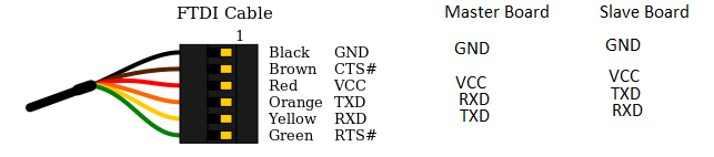
UART communication is one of the simplest methods to connect two MCUs together.We just connect RX-pin to TX-pin and vice versa.. You can know more about it from This great Sparkfun tutorial. So our wiring was as following: conneted TX and RX as I mentioned before between master and slave boards and connected also FTDI cable with both to power them up and also to use it as another slave to communicate with Serial Monitor to print values that help us indicate what's happening.
Master code was different than slave code. let's break it down here: The code was always checking on the status of the button which was Input pullup so it was always reading HIGH and if pressed it will read LOW. so simply if it reads LOW "when pressed" the board sends "1" to Serial and if not it sends "0". As following:
          void setup() {
            pinMode(1, INPUT_PULLUP); // set push button pin as input
            Serial.begin(9600);       // initialize UART with baud rate of 9600 bps
          }

          void loop() {

            if (digitalRead(1) == HIGH) { //if button is not pressed
              Serial.write('0');    // send the char '0' to serial
            }

            else {  // if button is pressed
              Serial.write('1');   // send the char '1' to serial
            }

          }
As for Slave board code, It was always reading from Serial and putting that reading into a variable. then checking if that variable was 1 or 0 if it is "1" it will make the LED pin HIGH if not the LED pin stays LOW. Here is the code:
          void setup() {
            pinMode(0, OUTPUT);      // set LED pin as output
            digitalWrite(0, LOW);    // switch off LED pin
            Serial.begin(9600);       // initialize UART with baud rate of 9600 bps
          }

          void loop() {
            if (Serial.available()) {
              char data_rcvd = Serial.read();   // read one byte from serial buffer and save to data_rcvd
              if (data_rcvd == '1')
                digitalWrite(0, HIGH); // switch LED On
              if (data_rcvd == '0')
                digitalWrite(0, LOW);  // switch LED Off
            }
          }
I2C communication was also as simple as connecting two wires which are SDA "Serial Data" and SCL "Serial Clock" between boards. You can know more about it from This great Sparkfun tutorial.So the wiring was as following: We connected the FTDI cable to power both boards, connected both "SDA" pins together and "SCL" pins as well. Also connected Slave board RX and TX with the ones of FTDI cable so we can print messages indicating the status of the LED whether it was turned on or not.
Master code here is pretty similar to the one we used in UART communication. We just added the LED in the Master's board as an indicator so nothing happed when we first ran the code so we just needed something to change while pressing the button :D. The main difference here is that we used Wire library which is mainly for I2C communication - we didn't add the pins numbers in the code - the code was basically starts to communicate with a specific board here it is "8" and then starts communication and depending on the status of the button it either sends 1 or 0 then ends communication.
          #include <Wire.h>

          void setup() {
            Wire.begin(); // join i2c bus (address optional for master)
            pinMode(1, INPUT_PULLUP); // set push button pin as input
            pinMode(0, OUTPUT);      // set LED pin as output ~Master board
            digitalWrite(0, LOW);    // switch off LED pin ~Master board
          }

          byte x = 0;

          void loop() {
            Wire.beginTransmission(8); // transmit to device #8
            Wire.write("L is ");        // sends five bytes

            if (digitalRead(1) == HIGH) { // if button is not pressed
              digitalWrite(0, 0); // turn off the LED on Master board
              x = 0;
              Wire.write(x);              // sends one byte "0"
              Wire.endTransmission();    // stop transmitting
            }

            if (digitalRead(1) == LOW) { // if button is pressed
              digitalWrite(0, 1); // turn on the LED on Master board
              x = 1;
              Wire.write(x);              // sends one byte "1"
              Wire.endTransmission();    // stop transmitting
            }
            delay(500);
          }
As for the Slave board code, at the beginning of the code we add it to the I2C communication as number "8" then depending on the reading coming from the Master board it turns on or off the LED. And also prints that status on Serial monitor.
          #include <Wire.h>

          void setup() {
            Wire.begin(8);                // join i2c bus with address #8
            Wire.onReceive(receiveEvent); // register event
            Serial.begin(9600);           // start serial for output
            pinMode(0, OUTPUT);      // set LED pin as output
            digitalWrite(0, LOW);    // switch off LED pin
          }

          void loop() {
            delay(100);
          }

          // function that executes whenever data is received from master
          void receiveEvent(int howMany) {

            int x = Wire.read();    // receive byte as an integer
            Serial.println(x);         // print the integer

            if (x) // if x equals 1 or HIGH
              digitalWrite(0, 1); // turn on LED 1 > means HIGH

            else // if x euals 0
              digitalWrite(0, 0); // turn on LED 0 > means LOW
          }
P.S. At first when we ran the same two codes nothing happened at all. So, Our instructor Kamel said that we must connect SDA and SCL pins to PULLUP resistors so it would work. After we made that, It worked right away as follows.You can know more about it from Here
The individual assignment: was to design, build, and connect wired or wireless node(s) with network or bus addresses. So I made a wired connection using bus addresses through UART communication.
I used the same 2 boards from the group assignment. It is very similar to UART code between the 2 boards but the difference here is they are both slaves waiting for the data I write in the Serial Monitor, if the data sent is the ID number of a board it turns the led on and send data to Serial monitor then turns the led off. It was mainly 1 code but changing the ID number from each board. Here are the codes:
          #define myID 5 //ID of the board - change it with each board

          void setup() {
            pinMode(5, INPUT);       // set Tx pin as input
            pinMode(0, OUTPUT);      // set LED pin as output
            digitalWrite(0, LOW);    // switch off LED pin
            Serial.begin(9600);       // initialize UART with baud rate of 9600 bps
          }

          void loop() {
            if (Serial.available()) {
              char data_rcvd = Serial.read();   // read one byte from serial buffer and save to data_rcvd

              if (data_rcvd == '5') { // 5 is changed based on the board's ID number
                digitalWrite(0, HIGH); // switch LED On
                pinMode(5, OUTPUT); // set Tx pin as output so it starts transmitting data
                Serial.println("LED ON 5");
                delay(1000);
                digitalWrite(0, LOW); // switch LED On
                Serial.println("LED OFF 5");
                delay(1000);
                pinMode(5, INPUT);
              } // There is no Else for the if condition
            }
          }
          #define myID 7 //ID of the board - change it with each board

          void setup() {
            pinMode(5, INPUT);       // set Tx pin as input
            pinMode(0, OUTPUT);      // set LED pin as output
            digitalWrite(0, LOW);    // switch off LED pin
            Serial.begin(9600);       // initialize UART with baud rate of 9600 bps
          }

          void loop() {
            if (Serial.available()) {
              char data_rcvd = Serial.read();   // read one byte from serial buffer and save to data_rcvd

              if (data_rcvd == '7') { // 7 is changed based on the board's ID number
                digitalWrite(0, HIGH); // switch LED On
                pinMode(5, OUTPUT); // set Tx pin as output so it starts transmitting data
                Serial.println("LED ON 7");
                delay(1000);
                digitalWrite(0, LOW); // switch LED On
                Serial.println("LED OFF 7");
                delay(1000);
                pinMode(5, INPUT);
              } // There is no Else for the if condition
            }
          }
P.S. To be able to use 2 boards as slaves in the UART communication technique we had to make the TX pin as input when it wasn't sending data to make sure that no noise is happening or 2 boards are sending data in the same time. Plus, that was the exact same reason there are no else in the code, as both boards will send data at the same time if they weren't choosen.