


A couple of years ago, one of my best friends and I were participating in Maker Faire Cairo as Makers. She wanted to facilitate Engineering concepts to kids so we made a couple of prjects that day. One of them was a Bubbles Machine. It was a very low-fidelity project, made from a plastic bottle, CD, crafting sticks, 1 motor and all assembled with glue. Despite that it worked for only 5 minutes that day but I can't forget its impact on the kids and myself.
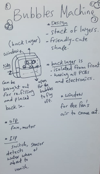
So, I decided to make one, one I am proud of this time. It's a project where its main actuators are a motor and a fan. its input signals maybe be an on/off switch based on user input or a sensor when the liquid needs refilling. Also, will need a casing as cute as the frog and hopefully more beautiful than my hand sketch.
General Specifications
- Its volume will be around 20*15*15cm
- It will have an ON/Off switch.
- When turned ON the wheel will rotate dipping into the water then the fan will be ON to blow away soap from the wheel creating many bubbles.
- ......
- CAD and Manufacturing:
- Designing the enclosure
- Mounting all electronic components
- Desiging Mechanisms of movement
- Desiging Tank refilling technique
- Electronics
- Design and fabricate output devices board: Motor and Fan
- Design and fabricate input devices board: Ultrasonic/IR...
- Communication between boards
- Power supply the device through and adaptor or a battery.
- Programming
- Writing each module code then integrating them into 1 code.
- Minimum:
- The machine will generate bubbles based on an ON/OFF switch "user input".
Main components: Fan, DC motor, and a switch. - The machine will make an alaram when the water level reaches its minimum.
Main components: IR sensor/....
- The machine will generate bubbles based on an ON/OFF switch "user input".
- Complete:
- The machine will be portable as it will run on a battery not adaptor.
- Nice To Have:
- The user will enter a timer for the machine to be ON then stops automatically.
Main components: buttons, and LCD/OLED screen
- The user will enter a timer for the machine to be ON then stops automatically.
- 1st week of May: Work on CAD design.
- 2nd week of May: Fabrication and testing output devices with water+soap.
- 3rd week of May: Working on Input sensor board + Communication between the 2 boards.
- 4th week of May: Integrating full circuit and code + Running with battery.
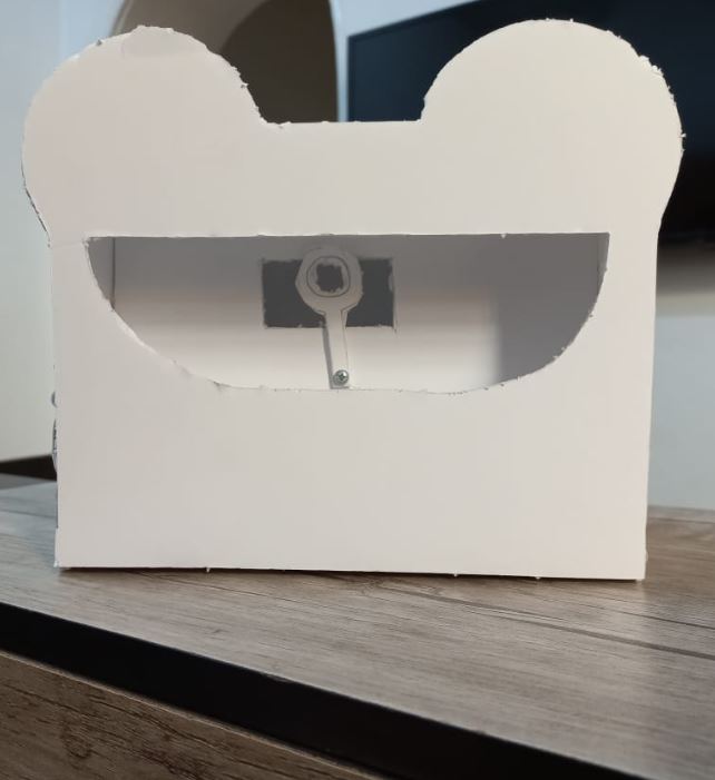
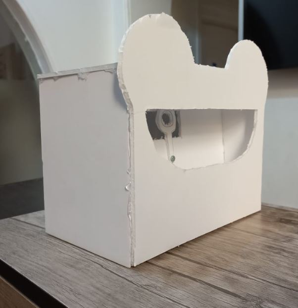
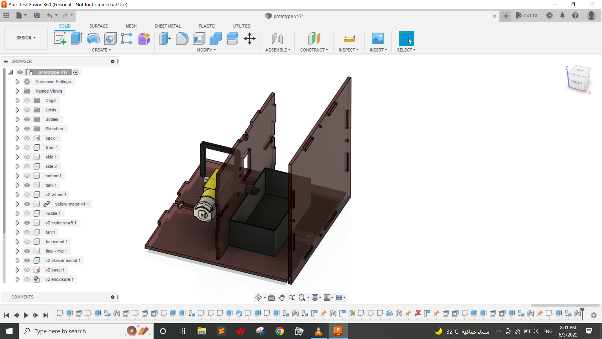
PrototypingI made a low-fidelity prototype to determine proper dimensions of the final project and to be able to visualize it more. It already helped me alot as I realized I can't pull out the tank part from the front side as the wheel will be connected to the shaft of the DC motor. So I had another idea to pull the tank down, Either by sliding motion using fitting "up and down motion" or using snap-fit connection with the main part like those locking parts in the lunch box for example. Here's what my prototype looked like.
 Step1: Finding functional components
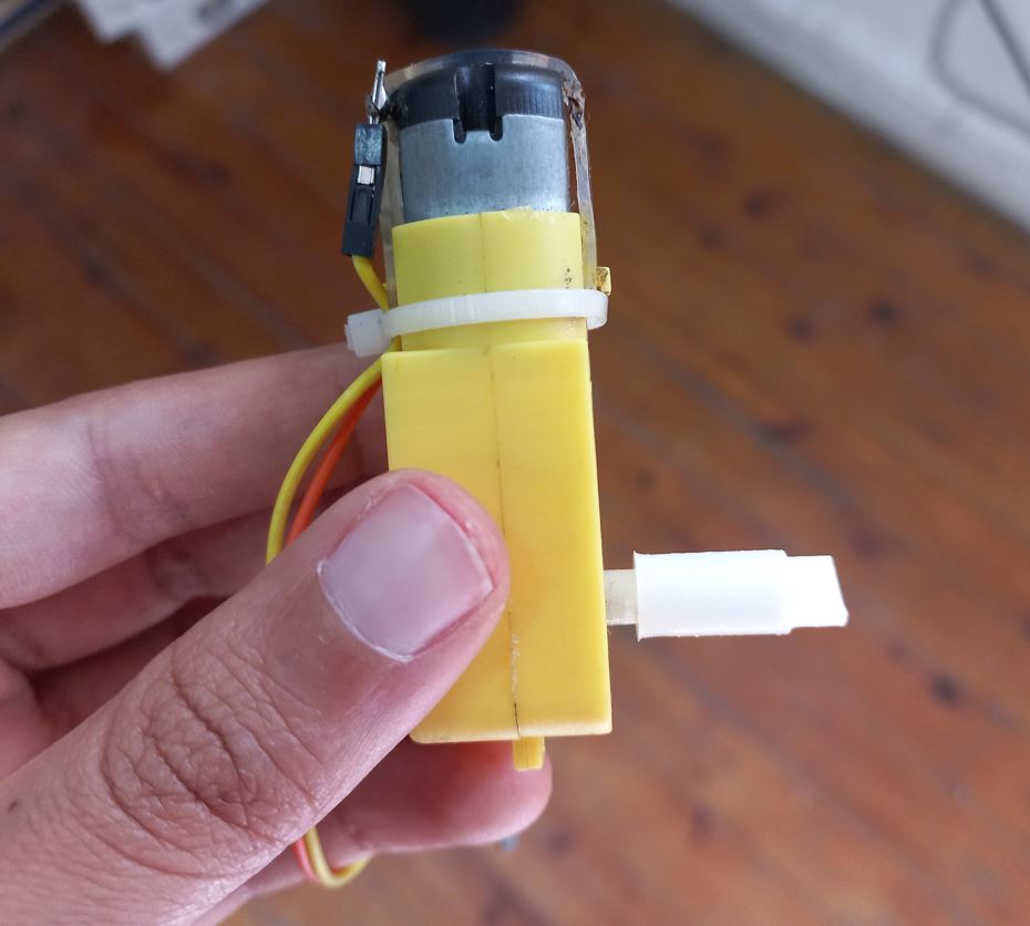
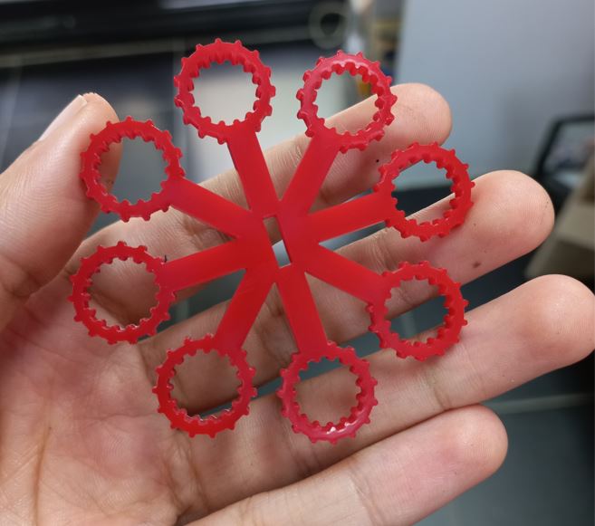
First of all I needed to make sure that the motor and the fan I choose can generate bubbles. first fan I tried wasn't strong enough to blow the bubbles away. so I had two more options, to try a stronger fan blower that is used in 3D printers, or a strong DC motor and 3D print fan blades and put them on its shaft. I tried both solution and Here are the results.
DC motor with 3D printed blades I found on thingiverse
3D printer blower fan
Step 2: Testing and Electronics DesignI choose the blower fan as it had smaller size and did the job done. after that I tested my minimum features to determine which microcontroller I will use.
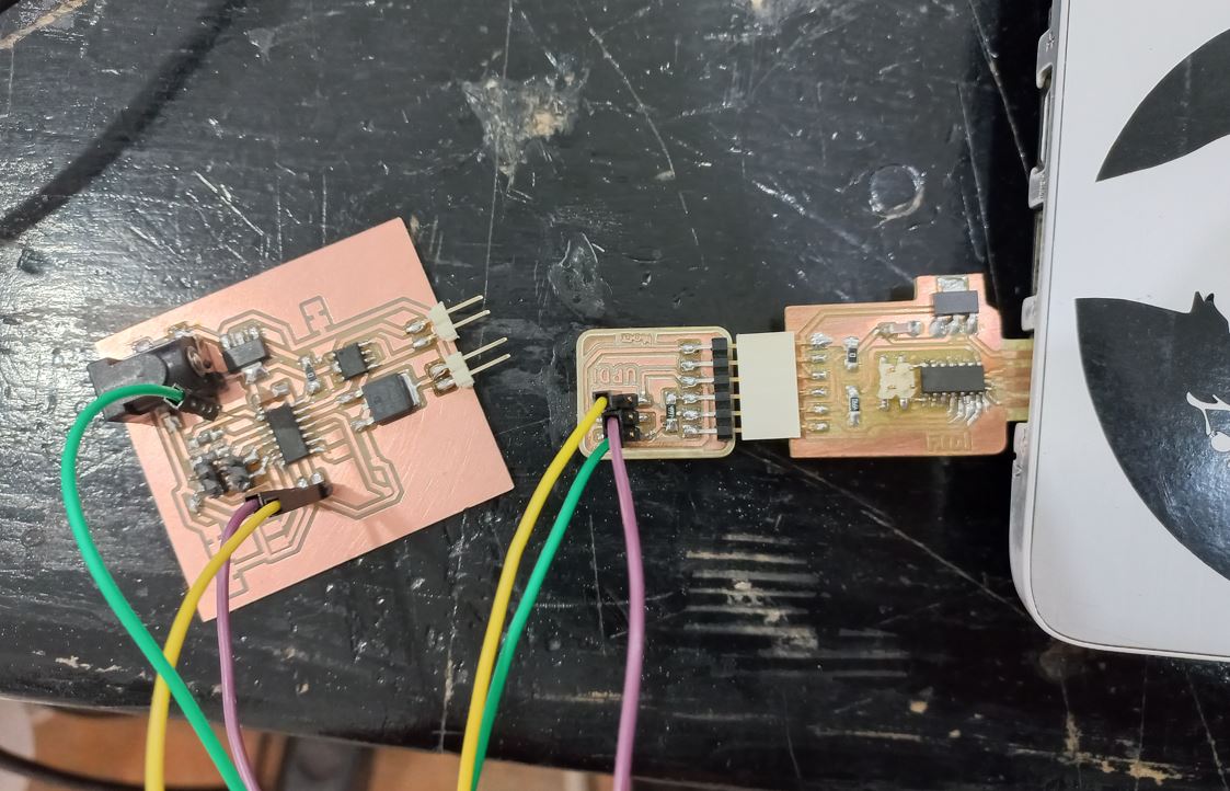
I wanted to measure the water level so it can make an alarm when the tank is empty so I needed to make serial communication so I could read the readings on the Serial port in Arduino IDE. I could use ATtiny44 to make that with Neil's code but the easier way was to use ATtiny1614 as it has hardware serial I didn't need to make a software serial like in the ATtiny44 case.
I used Neil's code for Capacitive sensing in input devices week as he also used ATtiny1624 which is so similar to ATtiny1614. Then I 3d printed a tank to put the bubble solution in and here is its result.
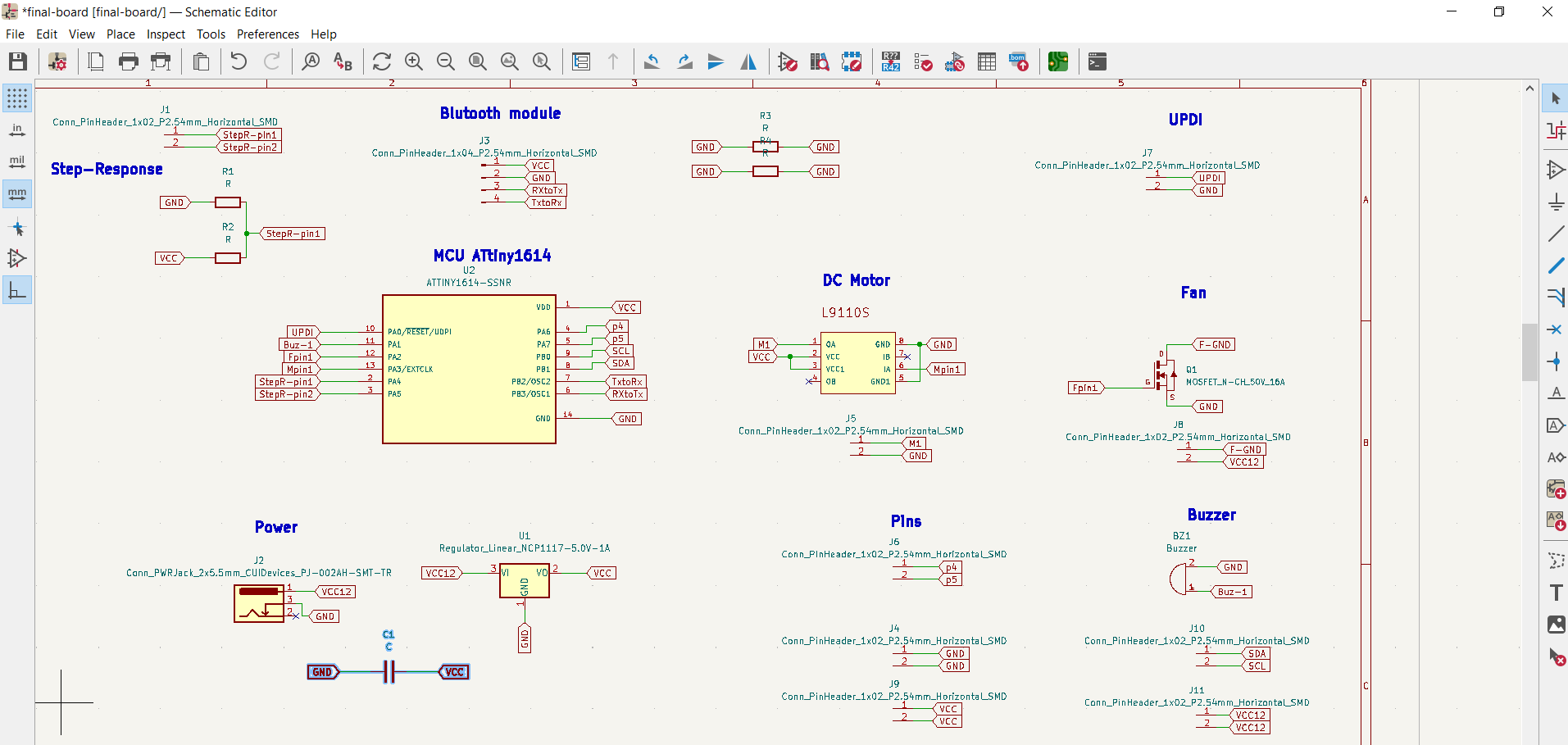
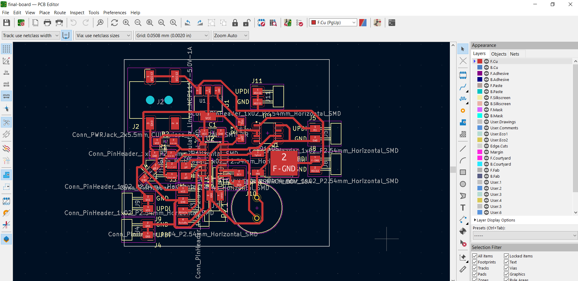
So after I determined which microcontroller and inputs/outputs I will use I started designing my final board on Kicad.
 Step 3: Testing and Programming
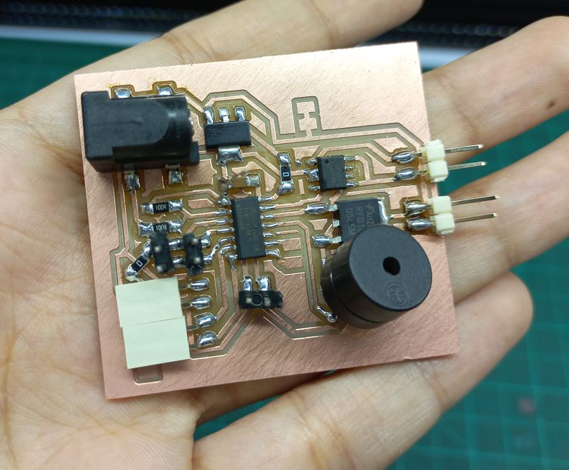
After the board was ready I started programming it each module alone then combined them In 1 single code. The code checks if the water level first, if it's less than a specific value then the tank is empty then the buzzer blinks. If the value more than the 34000 "which is the reading I got while trying capacitive sensing" then the tank is full, so the motor and the fan starts.
The final Code
                #define Fpin  9
                #define Mpin  10
                #define S  2
                #define Buzpin 8

                #define rxpin PIN_PA4 // receive pin
                #define txpin PIN_PA5 // transmit pin
                #define settle 100 // settle time
                #define samples 100 // number of samples to accumulate


                int val = 0;
                void setup() {
                  pinMode(Mpin, OUTPUT);
                  pinMode(Fpin, OUTPUT);
                  pinMode(Buzpin, OUTPUT);
                  pinMode(S, INPUT_PULLUP);

                  Serial.begin(115200); // start serial
                  pinMode(txpin, OUTPUT); // set transmit pin to output
                  analogSampleDuration(5); // speed up ADC sampling
                  analogReadResolution(10); // increase ADC resolution
                }

                void loop() {
                  val = digitalRead(S);
                  if (val == LOW) // if switch is pressed - ON mode
                  {
                    uint32_t StepRval = StepR();  // check water level sensor value
                    if (StepRval < 35000) //if water is empty
                    {
                      digitalWrite(Fpin, LOW);
                      digitalWrite(Mpin, LOW);
                      Blink();
                    }
                    else // if water is full
                    {
                      Huff();
                      digitalWrite(Buzpin, LOW);

                    }
                  }
                  else { //if switch is pressed again - OFF mode
                    digitalWrite(Buzpin, LOW);
                    digitalWrite(Fpin, LOW);
                    digitalWrite(Mpin, LOW);
                  }
                }


                void Huff() {
                  digitalWrite(Fpin, HIGH);
                  analogWrite(Mpin, 127);
                  delay(500);
                }

                void Blink() {
                  digitalWrite(Buzpin, HIGH);
                  delay(1000);
                  digitalWrite(Buzpin, LOW);
                  delay(1000);
                  digitalWrite(Buzpin, HIGH);
                  delay(1000);
                  digitalWrite(Buzpin, LOW);
                }

                uint32_t StepR () {
                  uint32_t up, down;
                  up = down = 0;
                  noInterrupts(); // disable interrupts while measuring
                  for (int i = 0; i < samples; ++i) {
                    digitalWriteFast(txpin, HIGH); // charge up
                    up += analogRead(rxpin); // read
                    delayMicroseconds(settle); //settle
                    digitalWriteFast(txpin, LOW); // charge down
                    down += analogRead(rxpin); // read
                    delayMicroseconds(settle); // settle
                  }
                  interrupts(); // enable interrupts after measuring
                  Serial.println(up - down); // send difference
                  Serial.flush(); // finish communicating before measuring
                  return up - down;
                }
Step4: Computer Aided Design
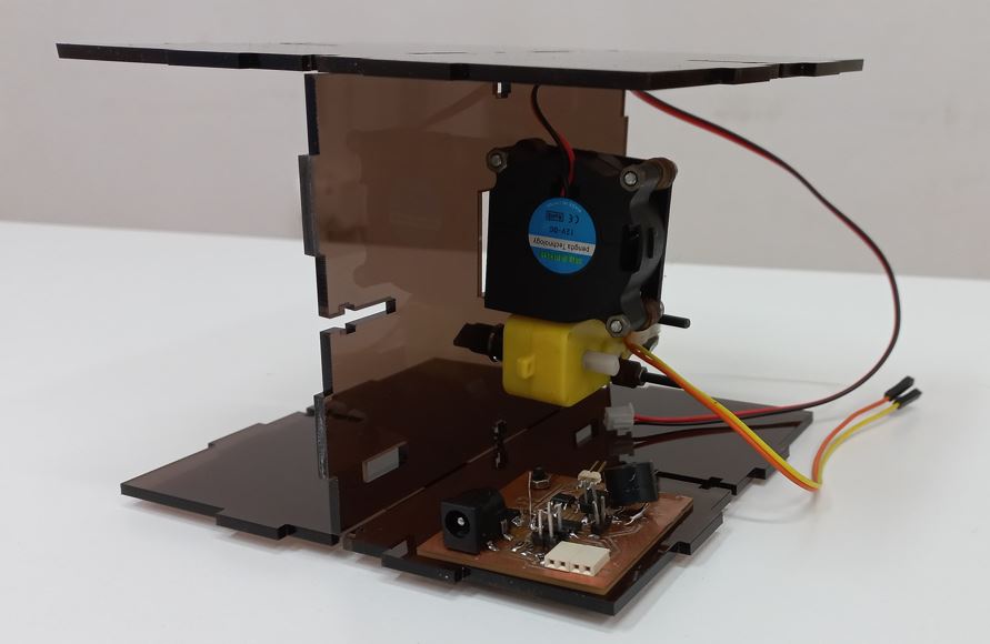
I started making a prototype using wood and just the part holding the motor and the fan + the base part to test the proper length between the fan and the wheel to blow the bubbles correctly.
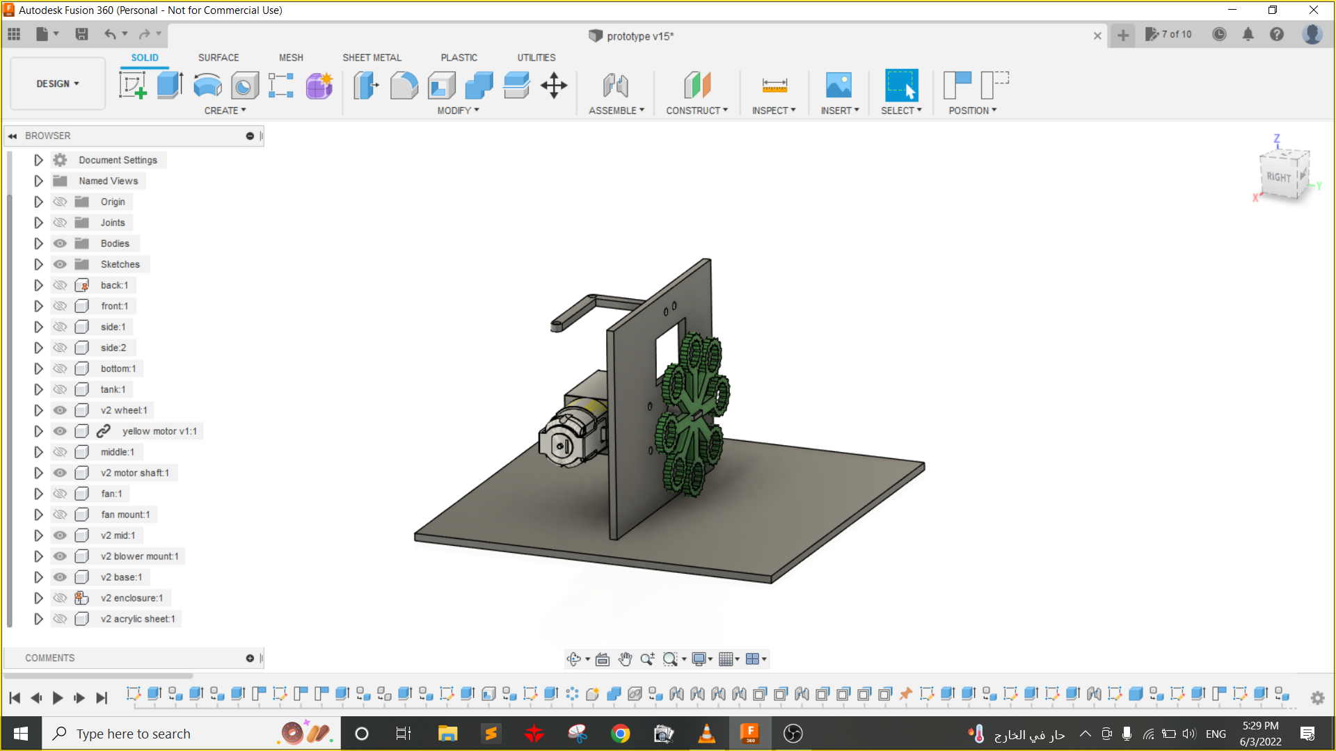
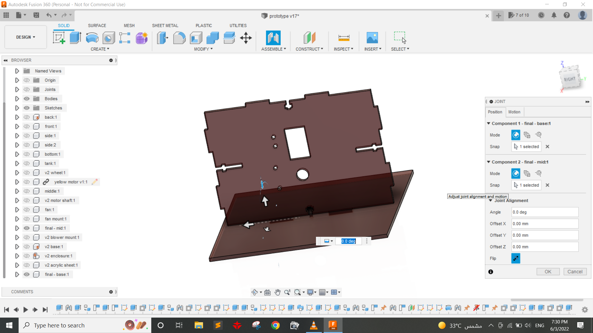
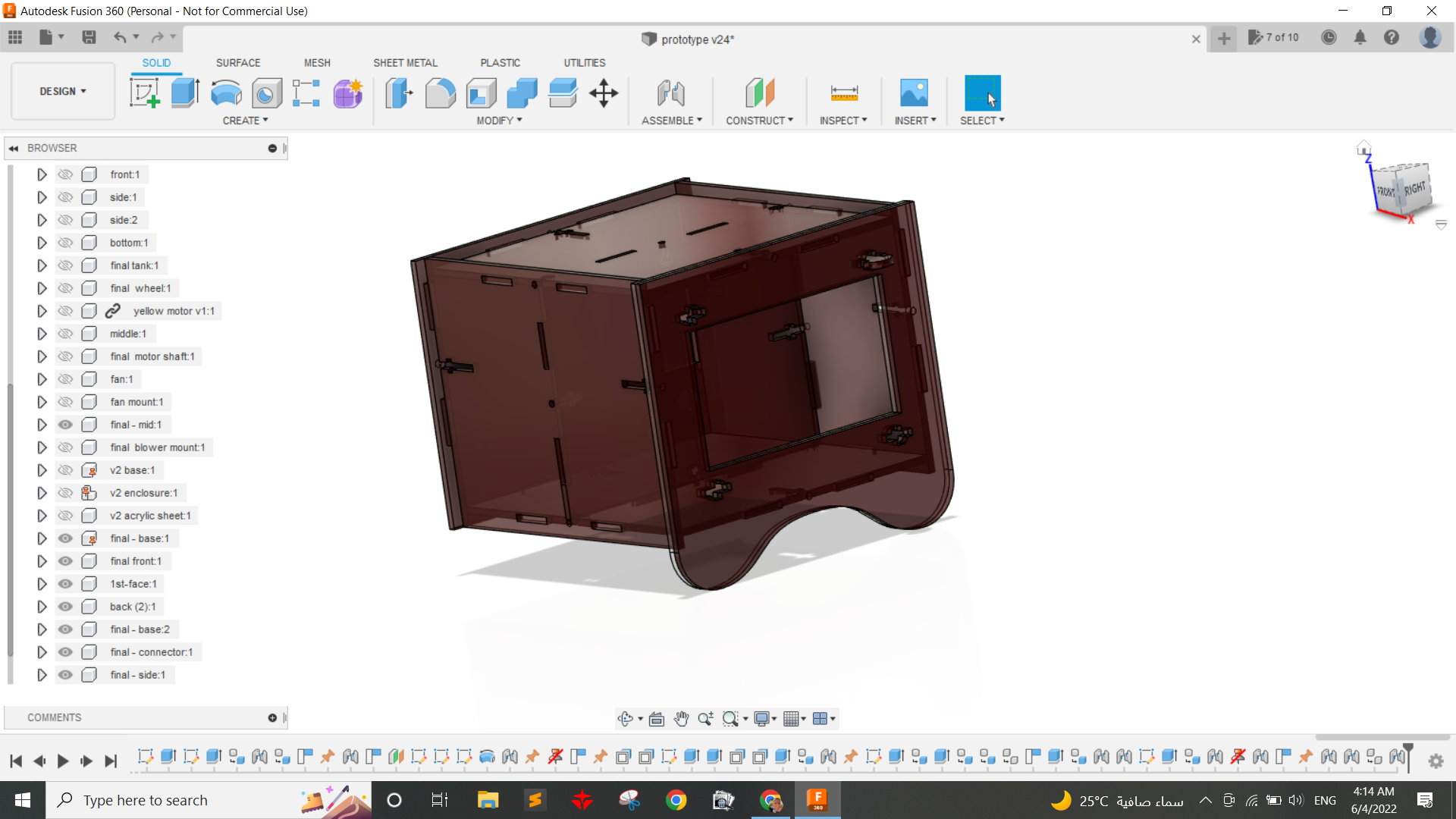
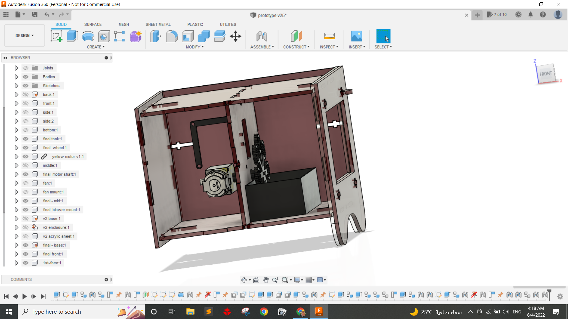
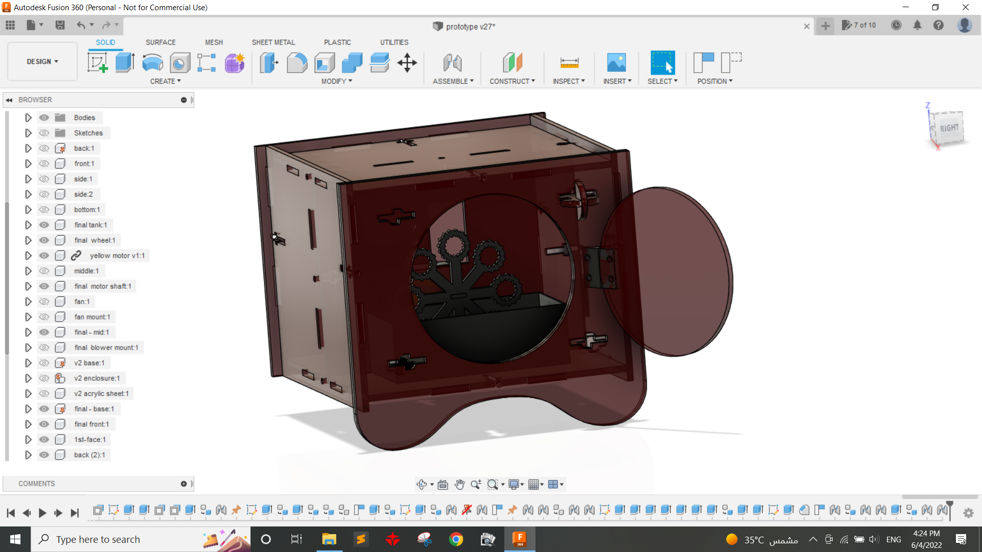
After that worked I started making a final design in Fusion 360.
 Step5: Fabrication
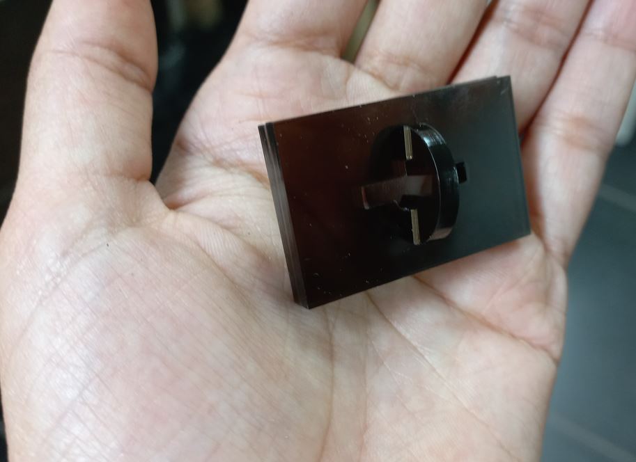
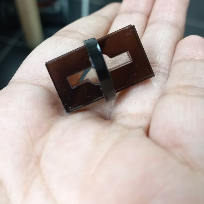
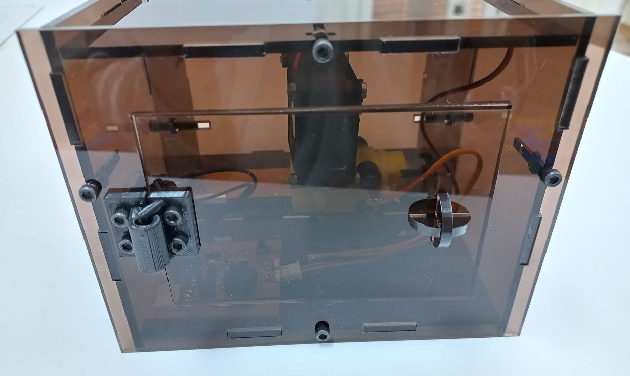
Following Omar Seif's advice taht good-looking projects are the simple ones that have one color or two. I decided to make all the parts with acrylic with the same color and all the 3d printed parts with also same color. Also, I have always admired transparent things so my final colors were transparent brown for the encolsure and black for 3d printed parts. but before I fabricate it all I needed to test some key parameters in the design like hinge's clearnce making it move well, the locking part for the front faces, and also fabricated the whole enclosre in wood first so detect if there is any problem with the design before making it in acrylic as acrylic is about 5 times the cost of wood. so here are some shots of that phase.
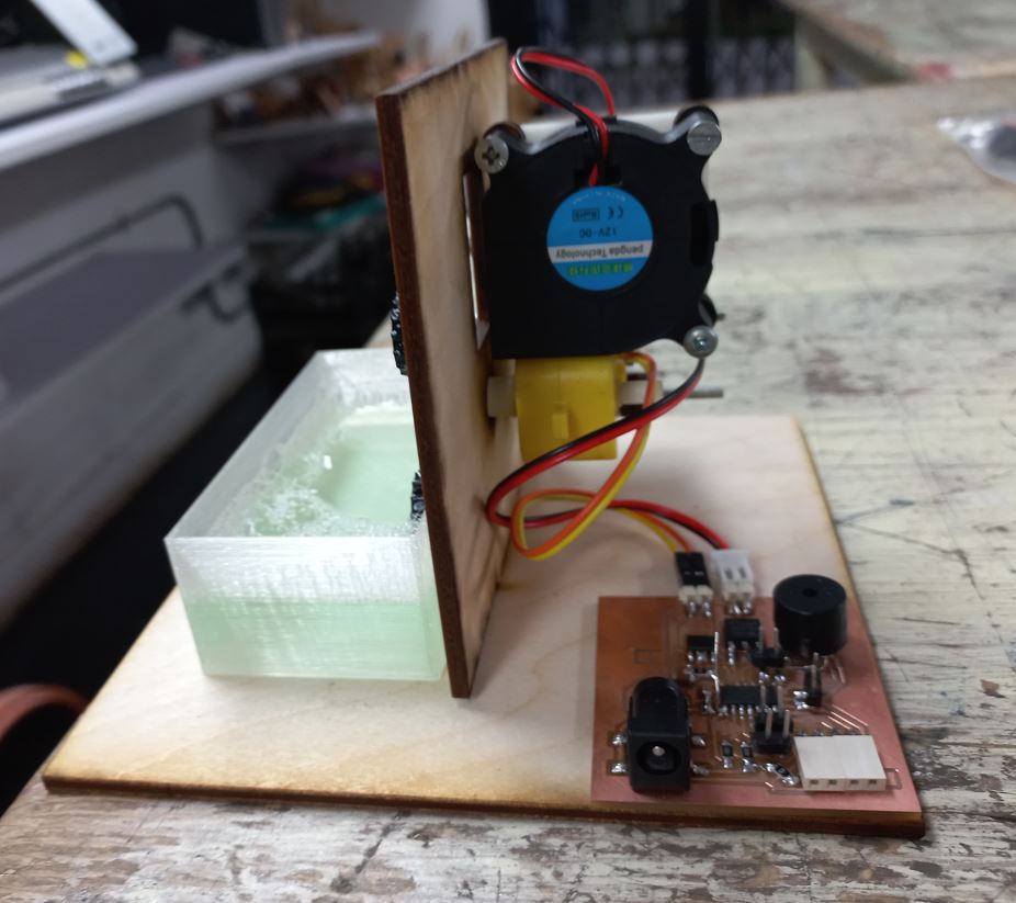
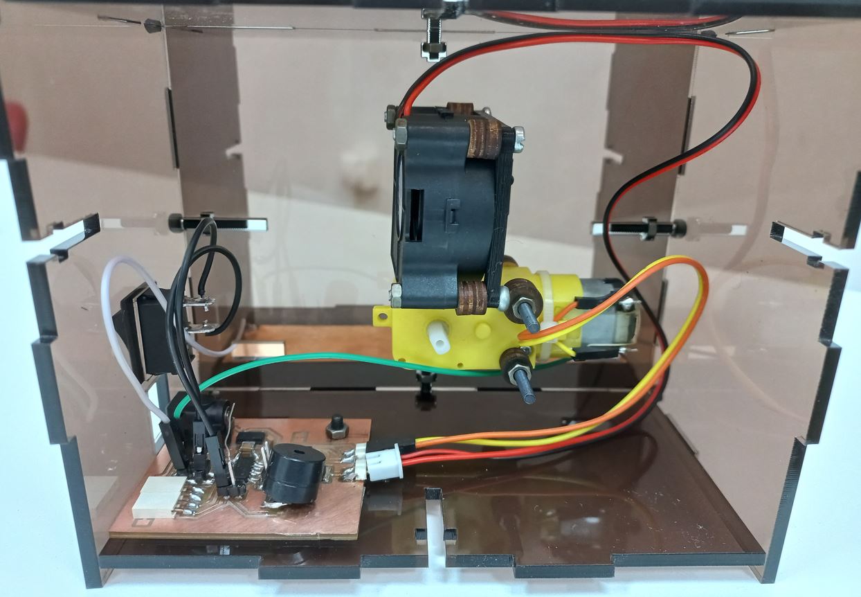
Happily after assembling the project with wooden parts it was all in its right place so I assembled it and also connected electronics and tested it and her is what it looked like.
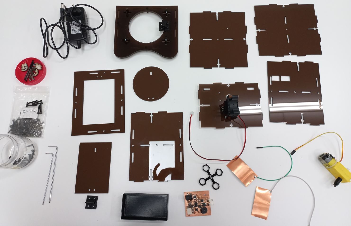
Now all is ready for final fabrication, so I 3D printed the water tank, motor and fan mounts, hinges for the doors. and Laser cut the whole enclosure.
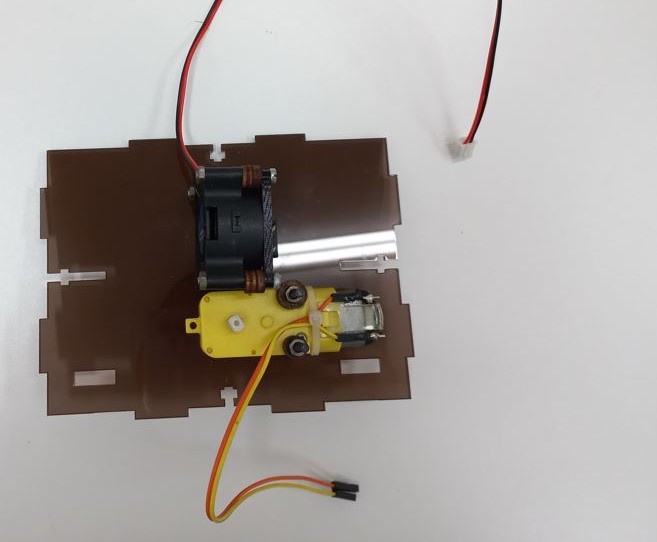
Step6: AssemblyNow that all components and pasrts are all set it waas time to assemble them, So I started with the motor and fan mounts as they are fixed to the middle part. Then, started assembling that parts together with M3 screws and nuts, also fixed that PCB at the back part with 1 M3 screw and happily it was all assembled just like in Fusion360.

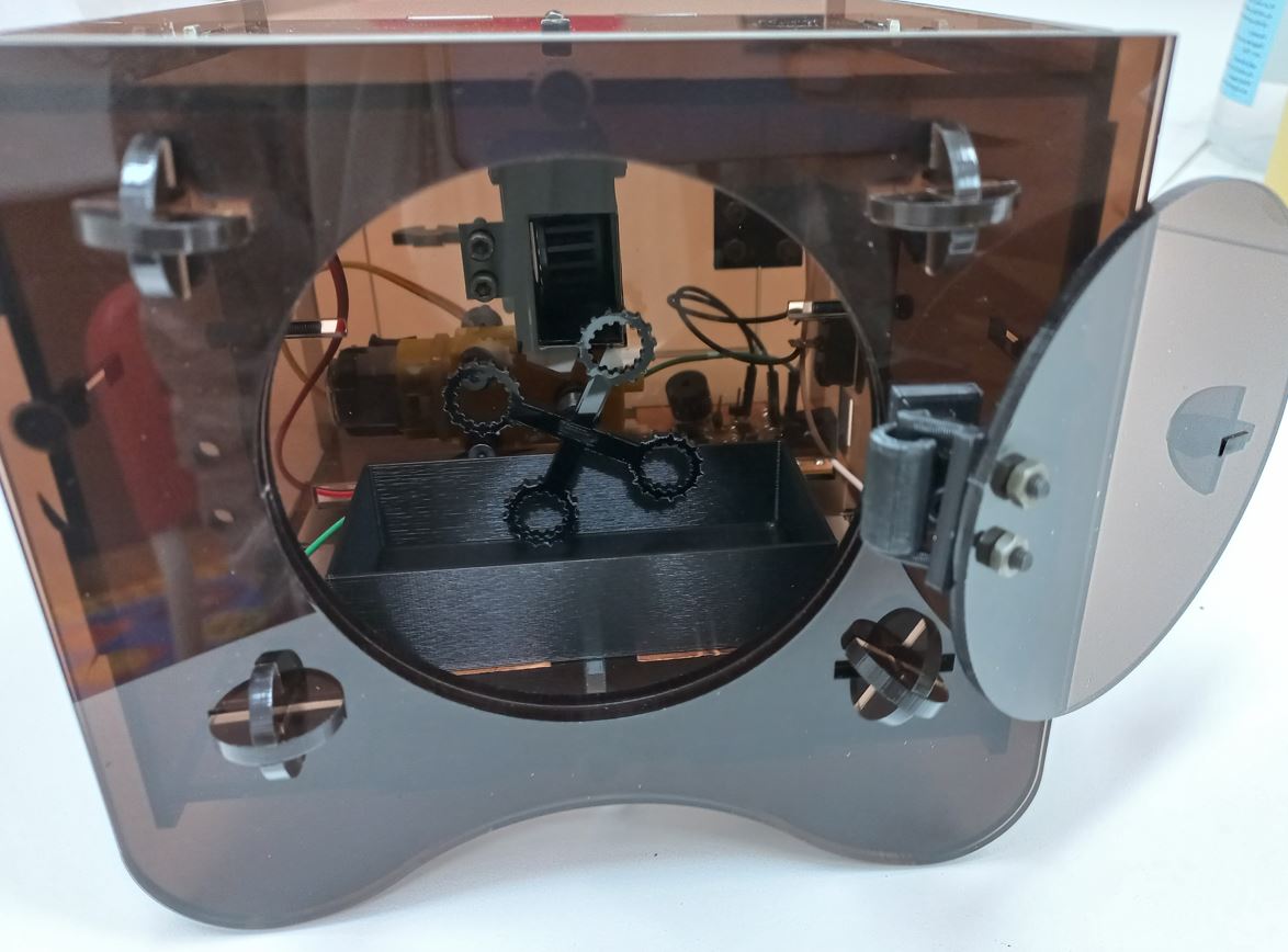
Finally, I plugged the power and tested it and it looked great. You can see it working in my presentation video at the first 45 seconds.
Source files: Fusion 360 filekicad project