Embedded Programming
Assignment requirements:
Group Assignment
- Compare the performance and development workflows for different microcontroller families.
- Document your work (in a group or individually).
Individual Assignment
- Read the datasheet for the microcontroller you are programming.
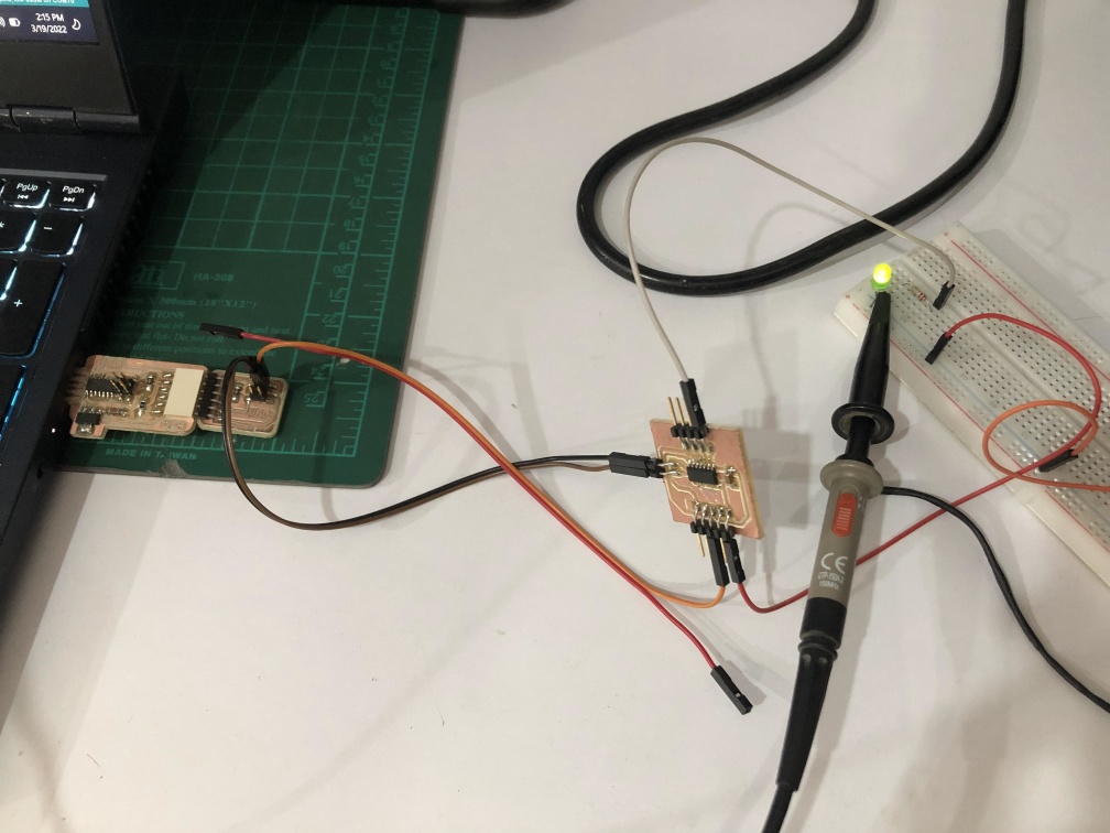
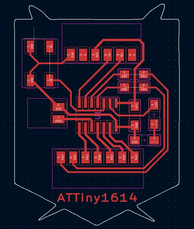
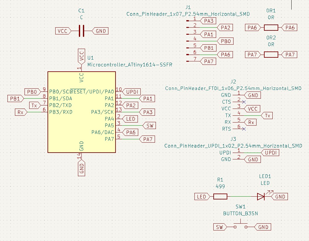
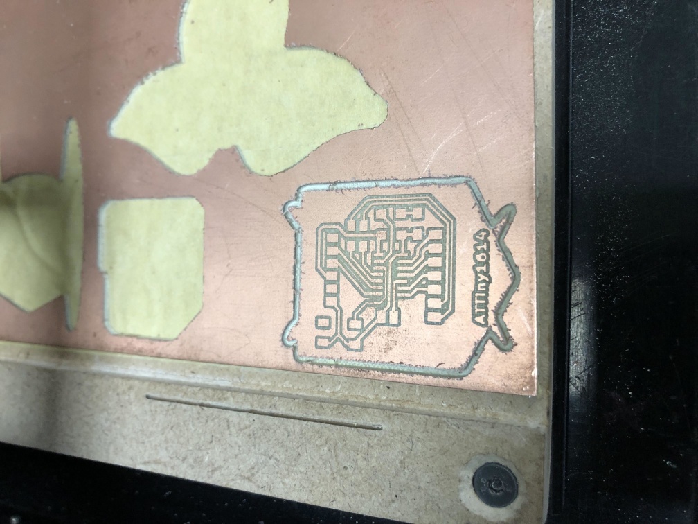
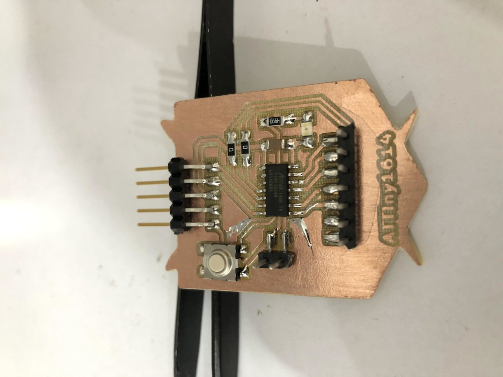
- Design an MCU board using Attiny1614 (Add the essential circuit - Add pin header for GPIOs - Add a switch and LED).
- Program the board to BLINK when the button is pressed using C and Arduino C.
Learning outcomes:
- Identify relevant information in a microcontroller datasheet.
- Implement programming protocols.
Assessment criteria
- Linked to the group assignment page.
- Documented what you learned from reading a microcontroller datasheet.
- Programmed your board.
- Described the programming process/es you used.
- Included your source code.
- Included a short 'hero video' of your board.
Group Assignment
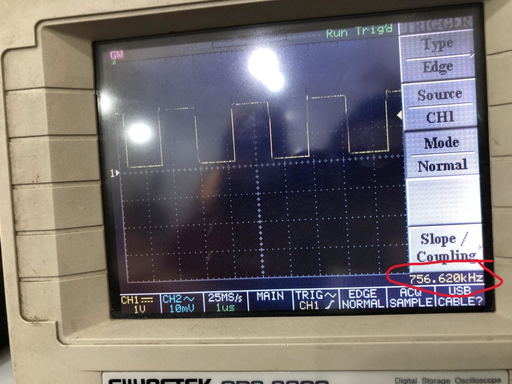
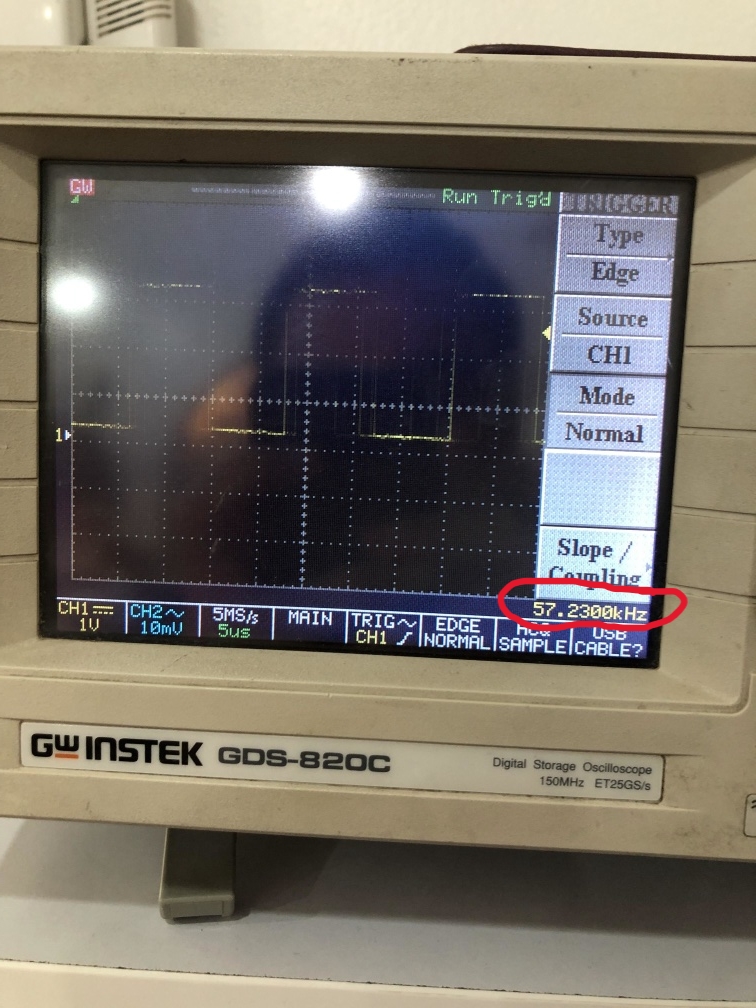
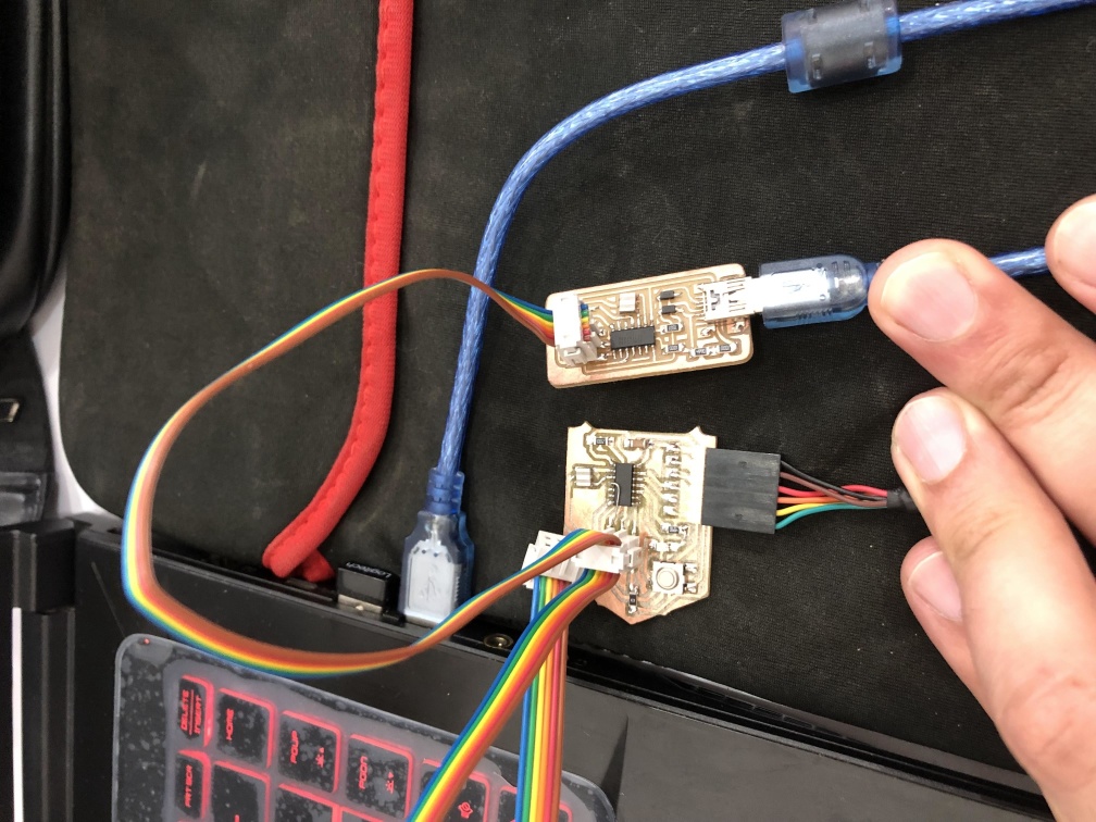
In this week we will learn more about programming and how the board can be effected when using different programming languages.
So we program our ATTiny44 and ATTiny1614 using Arduino code and C code.
ATTiny44 "Arduino"
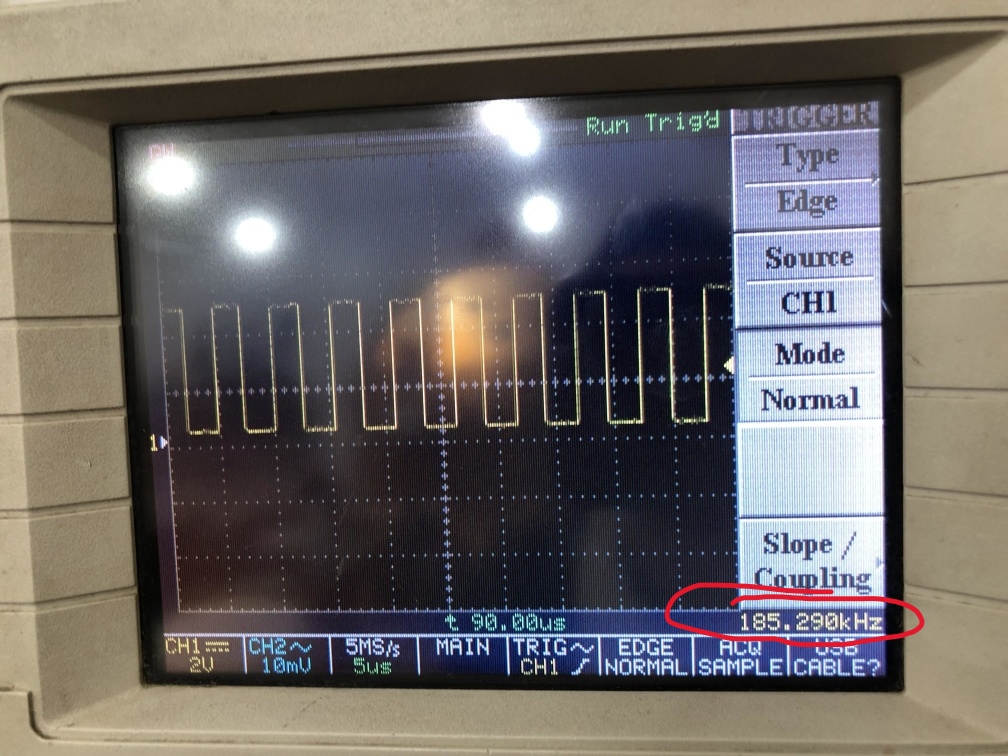
ATTiny44 "C"
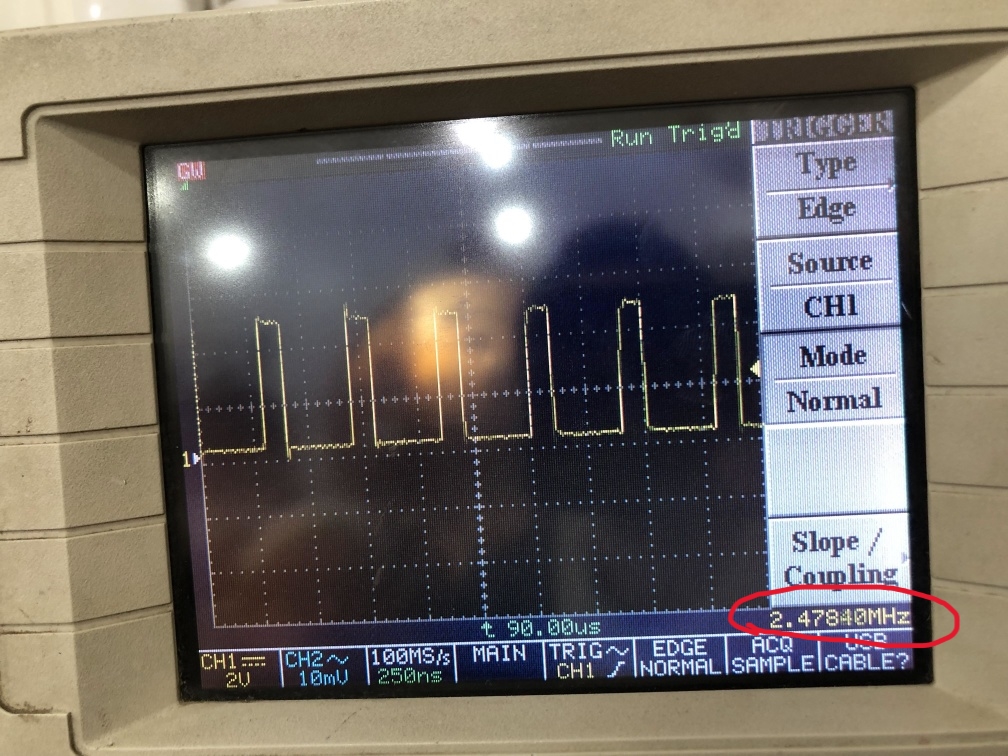
ATTiny1614 "Arduino"
ATTiny1614 "C"
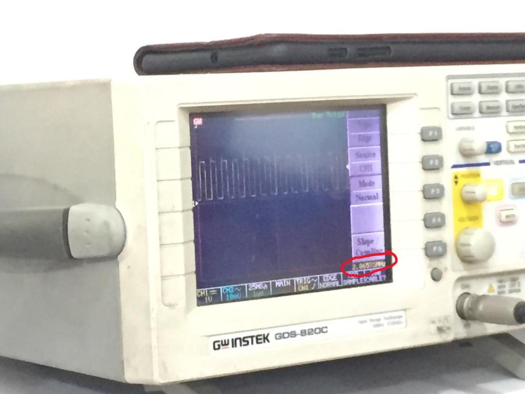
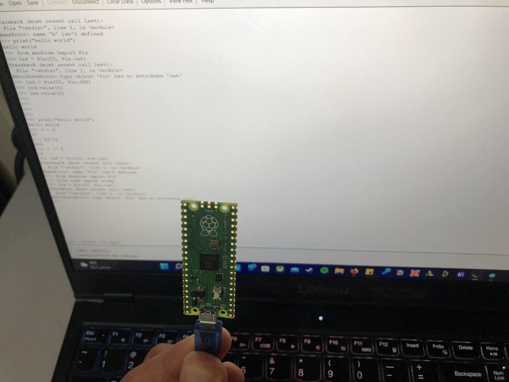
Raspberry Pi Pico
Individual Assignment
ATTiny44 "Arduino"
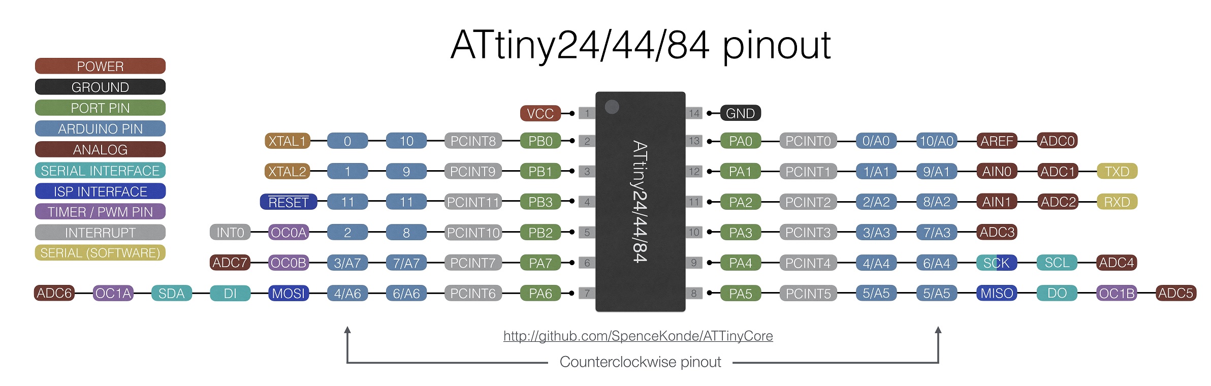
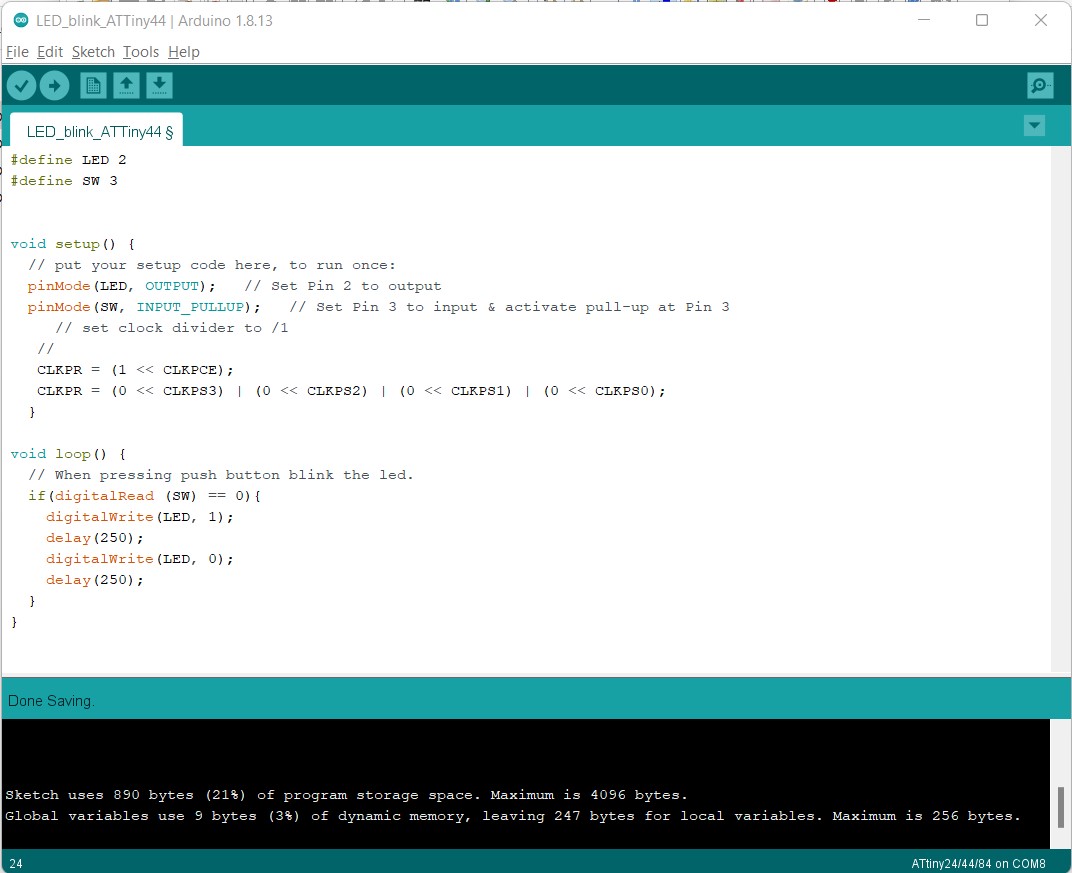
#define LED 2
#define SW 3
void setup() {
// put your setup code here, to run once:
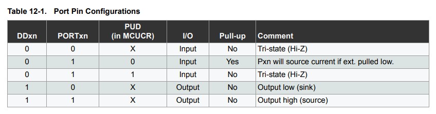
pinMode(LED, OUTPUT); // Set Pin 2 to output
pinMode(SW, INPUT_PULLUP); // Set Pin 3 to input & activate pull-up at Pin 3
// set clock divider to /1
//
CLKPR = (1 << CLKPCE);
CLKPR = (0 << CLKPS3) | (0 << CLKPS2) | (0 << CLKPS1) | (0 << CLKPS0);
}
void loop() {
// When pressing push button blink the led.
if(digitalRead (SW) == 0){
digitalWrite(LED, 1);
delay(250);
digitalWrite(LED, 0);
delay(250);
}
}
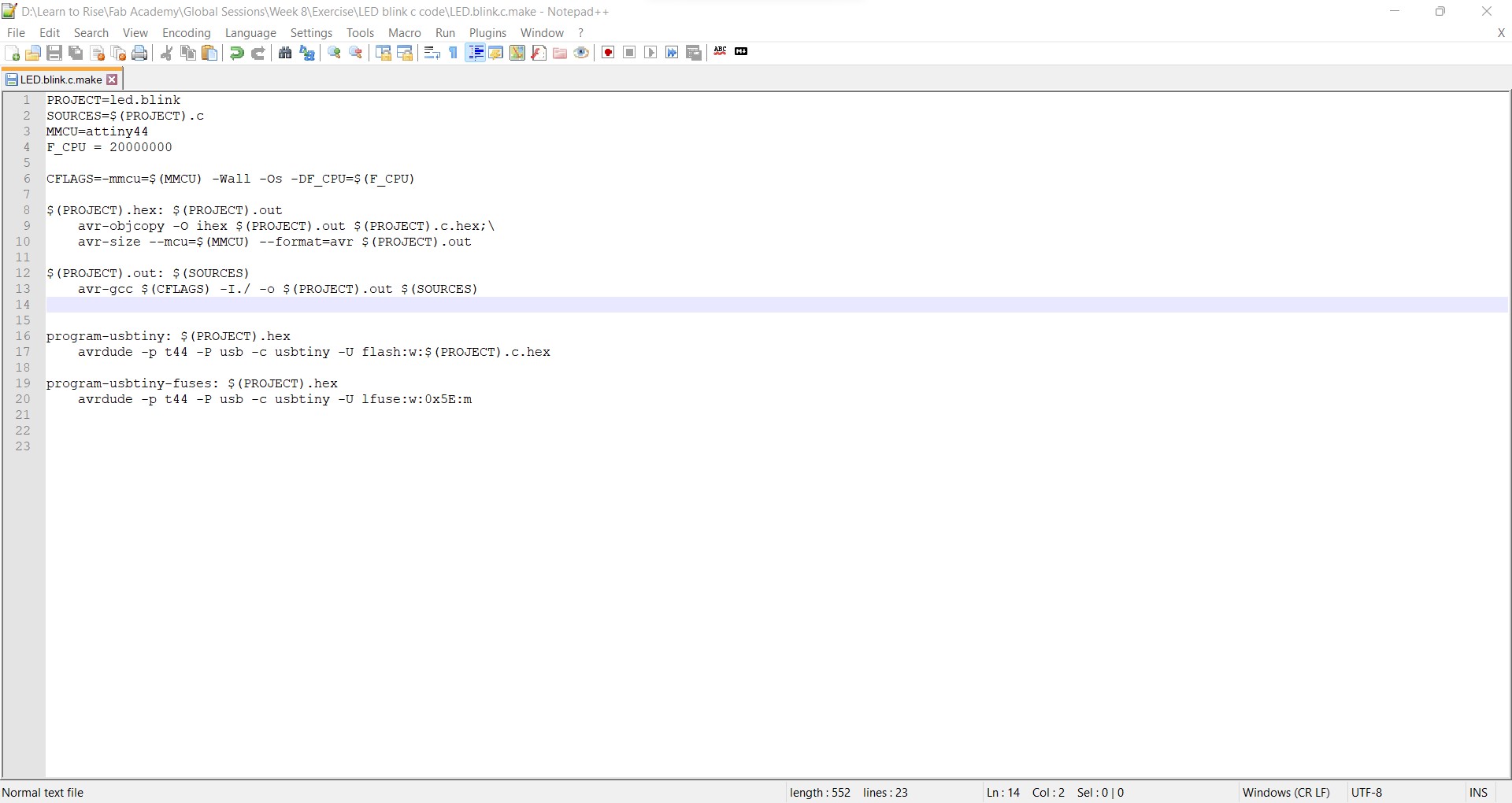
ATTiny44 "C"
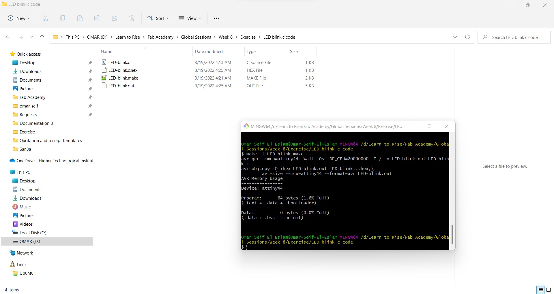
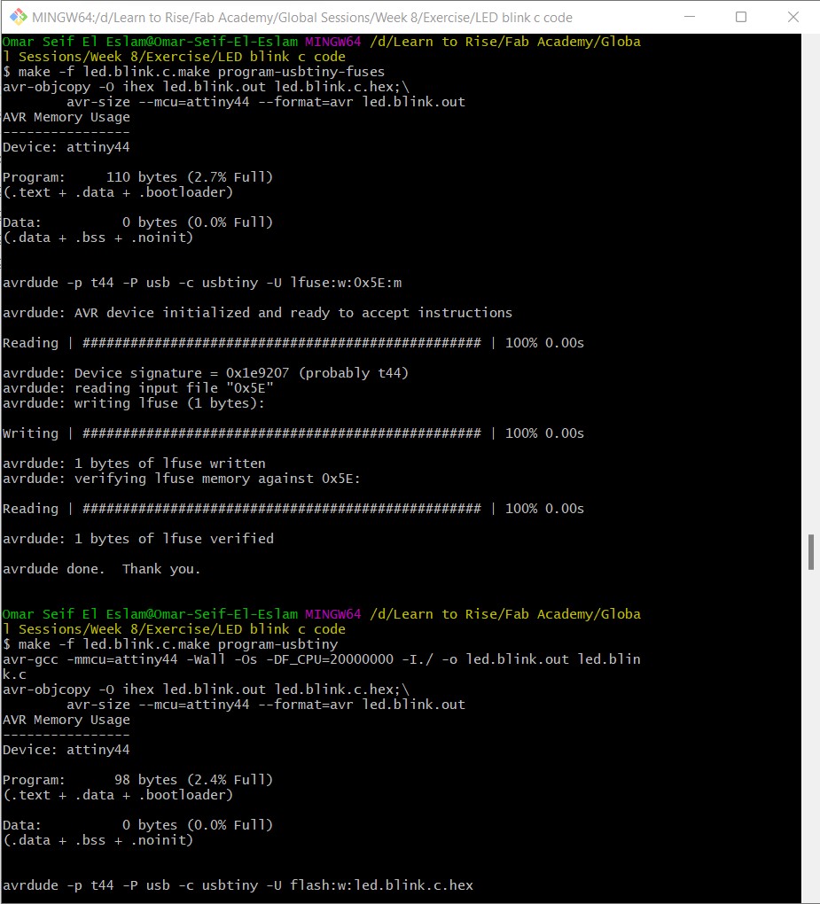
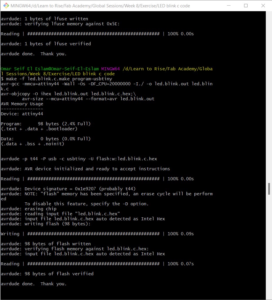
make -f ed.blink.c.make then > make -f led.blink.c.make program-usbtiny-fuses
then > make -f led.blink.c.make program-usbtiny
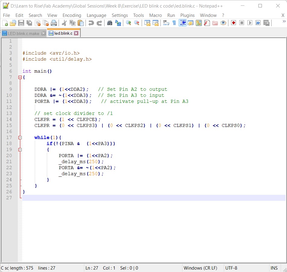
                        #include
                        #include

                        int main()
                        {

                            DDRA |= (1<<DDA2);   // Set Pin A2 to output
                            DDRA &= ~(1<<DDA3);  // Set Pin A3 to input
                            PORTA |= (1<<DDA3);   // activate pull-up at Pin A3

                            // set clock divider to /1
                            CLKPR = (1 << CLKPCE);
                            CLKPR = (0 << CLKPS3) | (0 << CLKPS2) | (0 << CLKPS1) | (0 << CLKPS0);

                            while(1){
                                if(!(PINA &  (1<<PA3)))
                                {
                                    PORTA |= (1<<PA2);
                                    _delay_ms(250);
                                    PORTA &= ~(1<<PA2);
                                    _delay_ms(250);
                                }
                            }
                        }
ATTiny1614 "Arduino"
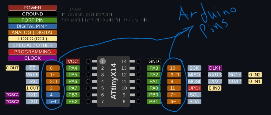
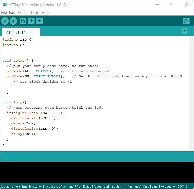
                            #define LED 0
                            #define SW 1


                            void setup() {
                              // put your setup code here, to run once:
                              pinMode(LED, OUTPUT);   // Set Pin 2 to output
                              pinMode(SW, INPUT_PULLUP);   // Set Pin 3 to input & activate pull-up at Pin 3

                              }

                            void loop() {
                              // When pressing push button blink the led.
                              if(digitalRead (SW) == 0){
                                digitalWrite(LED, 1);
                                delay(250);
                                digitalWrite(LED, 0);
                                delay(250);
                              }
                            }
ATTiny1614 "C"
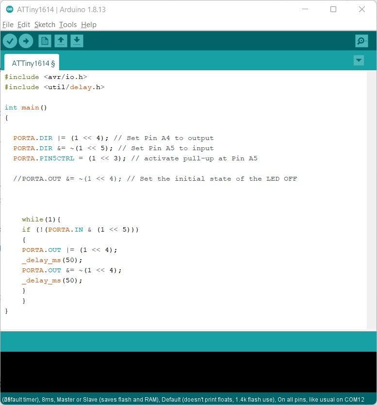
                                #include
                                #include

                                int main()
                                {

                                  PORTA.DIR |= (1 << 4); // Set Pin A4 to output
                                  PORTA.DIR &= ~(1 << 5); // Set Pin A5 to input
                                  PORTA.PIN5CTRL = (1 << 3); // activate pull-up at Pin A5

                                  //PORTA.OUT &= ~(1 << 4); // Set the initial state of the LED OFF


                                    while(1){
                                    if (!(PORTA.IN & (1 << 5)))
                                    {
                                    PORTA.OUT |= (1 << 4);
                                    _delay_ms(50);
                                    PORTA.OUT &= ~(1 << 4);
                                    _delay_ms(50);
                                    }
                                    }
                                }