


Here is my Hero-shot of the week! I programmed ATtiny44 using Arduino C using Arduino IDE and also used C language and went through editing the make file and uploading hex file and fuses using Git Bash. Hopefully I will also program one of the new Attiny family which is Attiny 1614.
Let's start first with the group assignment
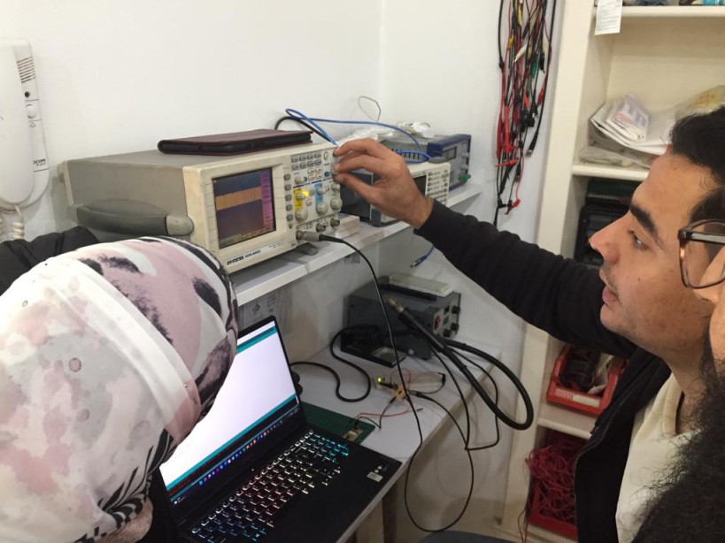
We wanted to test the performance of the board if we changed the programming language. So we used different boards which are Hello echo with Attiny44 micro-controller and Hello echo with Attiny1614 micro-controller and lastly Rasberry Pi pico.
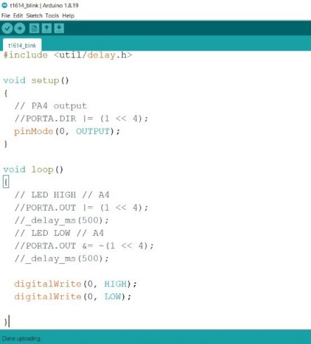
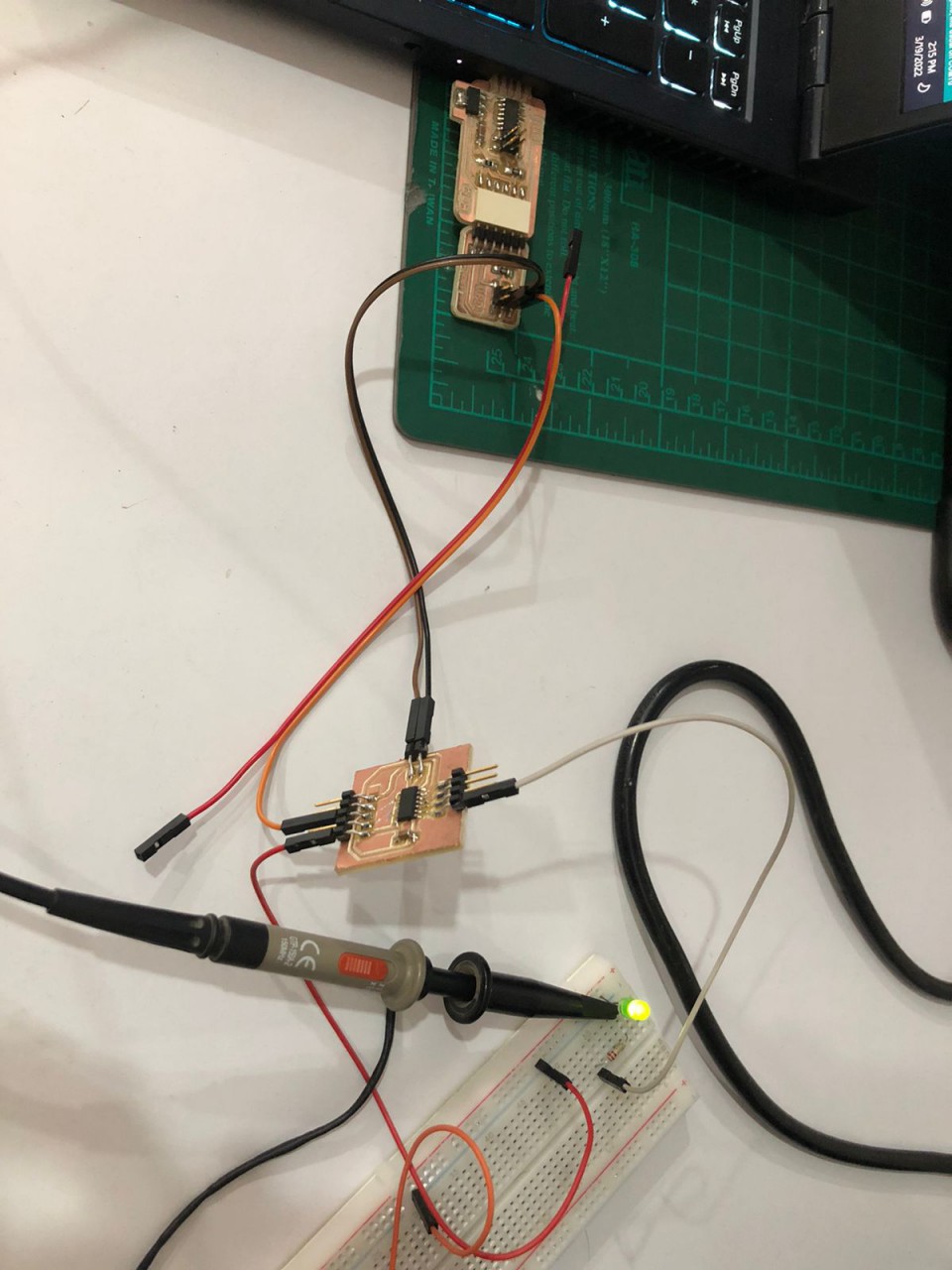
Attiny44To be able to test the speed of excuting the program we turned a LED on and off without using delay. Then to be able to view that changing wave we connected the Oscilloscope with 1 leg of the LED. so we used the following code in Arduino C
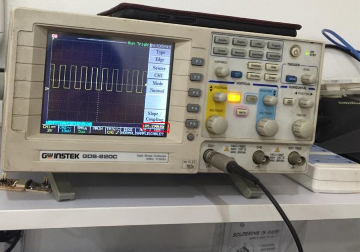
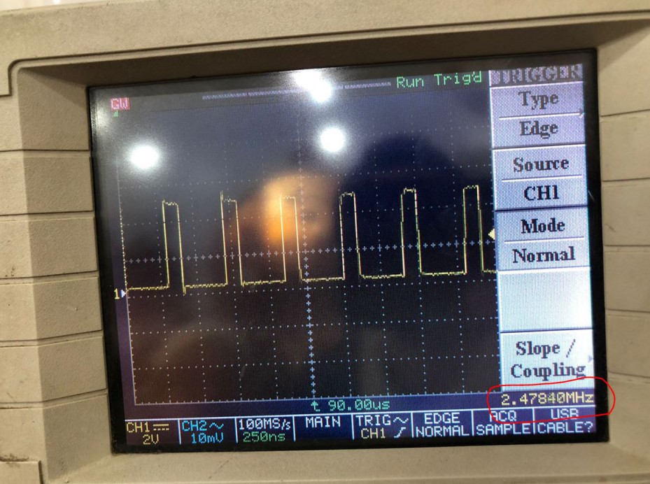
When we used C code the frequency of the wave was 2.4MHZ while in using Arduino C the frequency was 185KHZ!! which is almost 140 times slower :o
 Attiny1614
We repeated the past operation also on the 2nd board which had ATtiny1614 as its micro-controller. The frequency of the wave was 2.8MHZ while in using Arduino C the frequency was only 850KHZ!!
Rasberry Pi Pico
To be able to program Rasberry Pi we used Python programming language which works a lot differently as Python runs the code line by line so it looked like the next photo
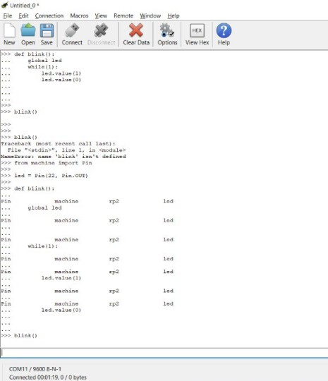
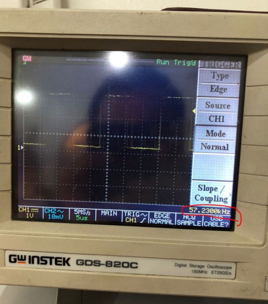
The frequency of the wave was the least while using python which was 57KHz.
Conclusion
As we compared the results from each language we reached that C is considered low-level programming language so it's close the machine code which is 0s and 1s, a bit higher comes Arduino C as it uses big libraries to translate commands like "pinMode" and "digitalWrite" which takes a lot from the microcontroller's memory which leads to slower performance. Finally, Python is high-level programming language which is far from the machine's code but very simple for the user though. That's why it was the slowest in performance.
Now, The assignment!The assignment was to Read the datasheet for the microcontroller I am programming. Program the board to do something. So I programmed ATtiny44 to blink a LED when a button is pressed using C and Arduino C.
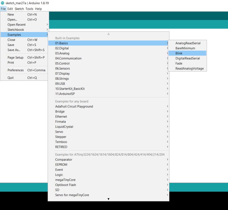
Arduino CAs I am familiar with Arduino C and Arduino IDE it was easy to understand. Also I didn't Have to type the code myself as Arduino already has saved examples, You can get it from File> Examples > Basic > Blink.
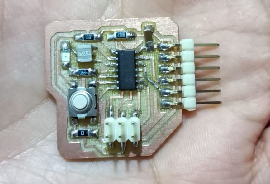
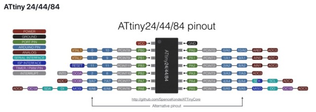
Then it will open a code ready for uploading. But I needed to tweek it a bit as in my Echo-Hello board I attached the LED with a specific pin so from the datasheet I needed to know which pin I connected the LED and the Button. So as the next 2 photos show I connected the LED on PB2 and the button on PA7. to Arduino PB2 is considered pin 8 at PA7 is pin 7.
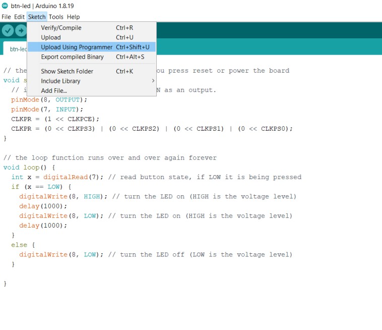
So In the code I added "if condition": if the button is pressed, set the LED on, delay, then off. It should know that the button is pressed as I connected the pin in the hardware to 5V which is VCC, But if the button is pressed it will connect the pin with 0V which is GND. Here is the Arduino code.
           // the setup function runs once when you press reset or power the board
            void setup() {
              // initialize digital pin LED_BUILTIN as an output.
              pinMode(8, OUTPUT);
              pinMode(7, INPUT);
              CLKPR = (1 << CLKPCE);
              CLKPR = (0 << CLKPS3) | (0 << CLKPS2) | (0 << CLKPS1) | (0 << CLKPS0);
            }

            // the loop function runs over and over again forever
            void loop() {
              int x = digitalRead(7); // read button state, if LOW it is being pressed
              if (x == LOW) {
                digitalWrite(8, HIGH); // turn the LED on (HIGH is the voltage level)
                delay(1000);
                digitalWrite(8, LOW); // turn the LED on (HIGH is the voltage level)
                delay(1000);
              }
              else {
                digitalWrite(8, LOW); // turn the LED off (LOW is the voltage level)
              }

            }
Now that the code is ready we need to upload it. To be able to to do we first need to download ATtiny44 core to be able to choose the board from Arduino IDE as the one we want to program. I followed this tutorial that helped my a lot. Tutorial link So after I installed the library successfully I needed to set some parameters like the clock and port..etc.
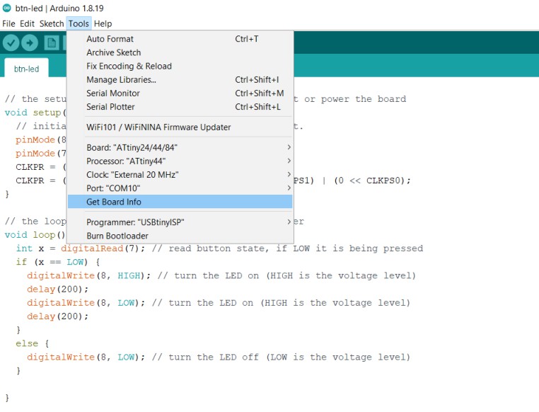
Now finally all is set to upload, so from Sketch choose upload using programmer, Also the button upload worked just fine too.
And yaay! it blinked. On for 1 sec off for 1 sec, repeat.
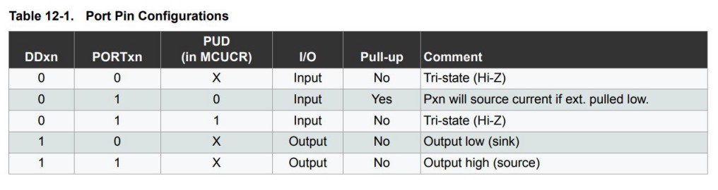
C LanguageAs we said before, C is close to the machine's code, So it talks directly to the registers inside the micro-controller. In the next photo we will see the 3 registers that controls the GPIO pins in ATtiny44.
- DDxn: Sets the pin as Input or output.
- Portxn: Controls the pin to be Input-Pullup if it is an input pin.
- Portxn: Also sets the pin to High or Low if it is an output pin.
Following those commands I built my 1st C code. I started with Neil's code first but ended up only taking the libraries and the clock divider to set the time correctly. Here is the code I built:
            #include <avr/io.h>
            #include <util/delay.h>

            int main(void) {
              // main
              // set clock divider to /1
              //
              CLKPR = (1 << CLKPCE);
              CLKPR = (0 << CLKPS3) | (0 << CLKPS2) | (0 << CLKPS1) | (0 << CLKPS0);
              //
              // initialize output/input pins
              // set btn i/p
              DDRA &= ~(1 << PA7);
              PORTA &= ~(1 << PA7);

              // set LED o/p
              DDRB |= (1 << PB2);
              PORTB &= ~(1 << PB2); // make it OFF
              //
              while (1) {
                // if btn == 0
                if (!(PINA & (1 << PA7)) ) { // AND-ing the pin reading with 0b10000000
                  //so it overwrite all others to 0s to filter
                  //them and get the reading we are interested in
                  //LED == 1
                  PORTB |= (1 << PB2); // (LED > ON) OR-ing with 0b10000000 so if it was 0 make it 1 and if 1 stays 1 + not changing other pins
                  //delay
                  _delay_ms(250);
                  //LED == 0
                  PORTB &= ~(1 << PB2); //(LED > OFF) AND-ing with 0b01111111 so if it was 1 make it 0 and if 0 stays 0
                  //+ AND-ing 1 to others, 0 and 1 is 0, 1 and 1 is 1 so not changing other pins
                  //delay
                  _delay_ms(250);
                }
              }
            }
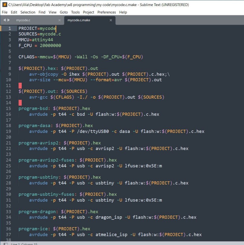
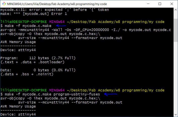
Then I saved the code as ".c" then edited Neil's Make file, just changed the project and sources name as follows:
Now all is ready to run Git Bash, so went to the folder that I saved both .c file and .c.make file then right click and choose open Git Bash here. Then used Neil's steps in the Hello-Echo board in programming as it is the same AVR toolchain in the next photo:
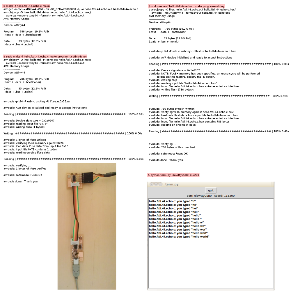
Also connected my FabISP programmer to my laptop, connected the programer to the board through 6-pin ISP protocol and then the board I want to program with my laptop through FTDI cable. Then from Git Bash used Neil's codes - but changing the name of the files of course -
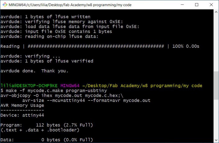
In the C code I made the delay only 0.25 sec so it could differ from the Arduino code to check if it really worked okay. Aaanndd it did!!
We aren't finished with this week! Now comes ATtiny1614
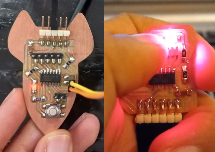
To be able to try different programming process I used a different MCU which is a newer version of the AVR family which is ATtiny1614! So I designed, fabricated, soldered, then programmed it. let's see how.
I started from the Echo Hello board of Neil's design.
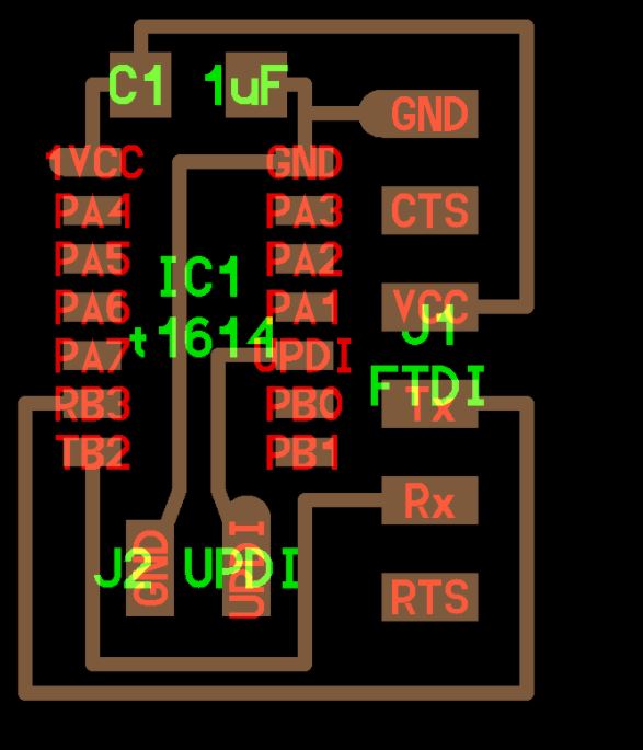
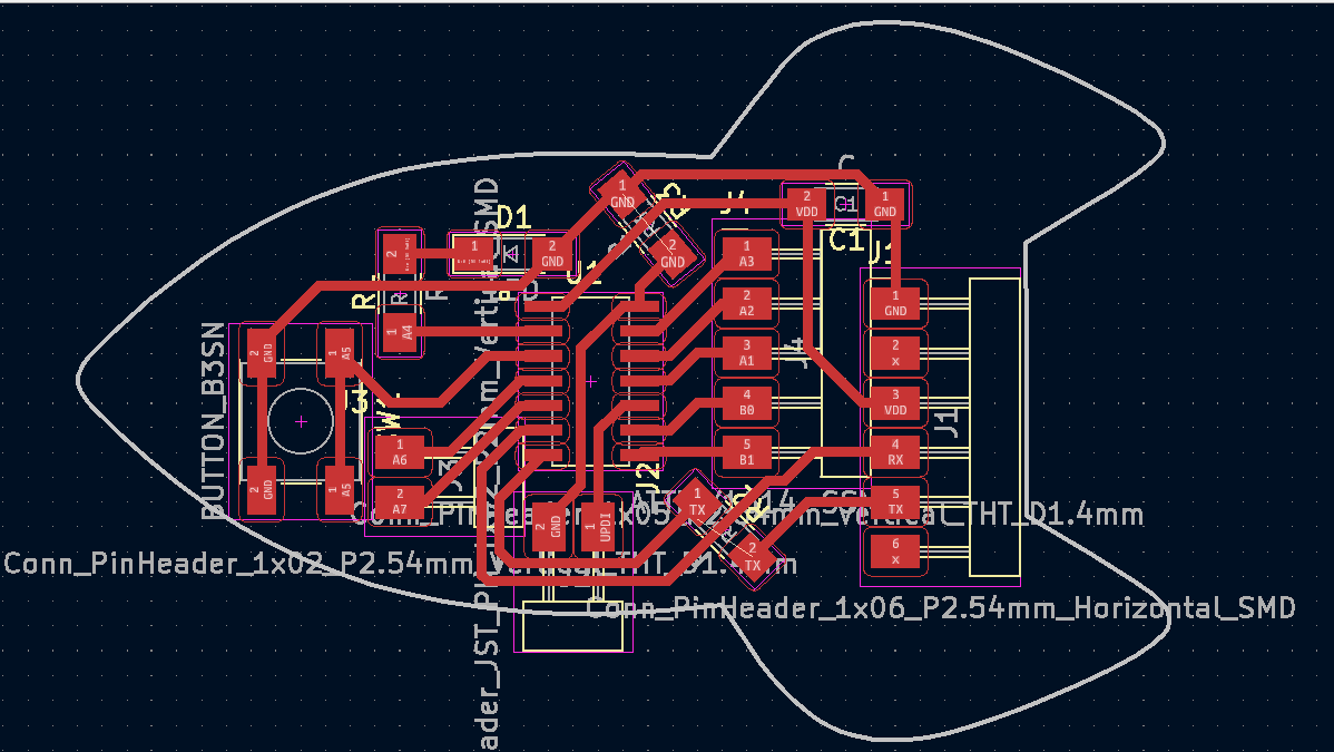
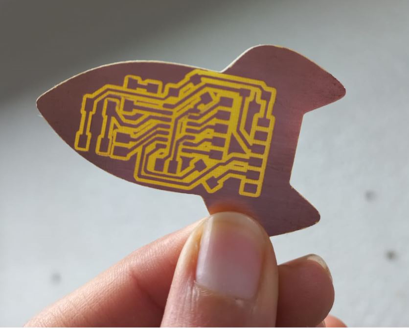
This board is so much easier for designing as it needs very few components to operate only a capacitor and UPDI programming pins are only 2 which are UPDI and GND, in addition to FTDI 6-pin connector and that is it! I then added an LED and a button and connected pin headers to all of the MCU's GPIO pins to be able to use them later in the next weeks. I added that cool rocket outline from file > import then choose the file which was in SVG extension
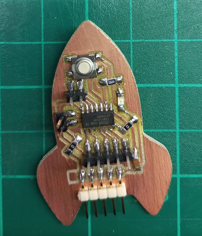
Then did the fabrication and soldering and that's how our beautiful board after I was done!
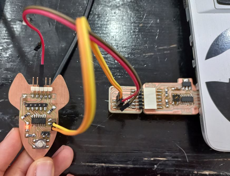
For programming I used UPDI programmer that I did in the Electronics production week, It is so simple as we just plug the programmer through the usb port on the laptop and connect UPDI & GND pins + VCC pin through the FTDI 6-pins, That's the hardware.
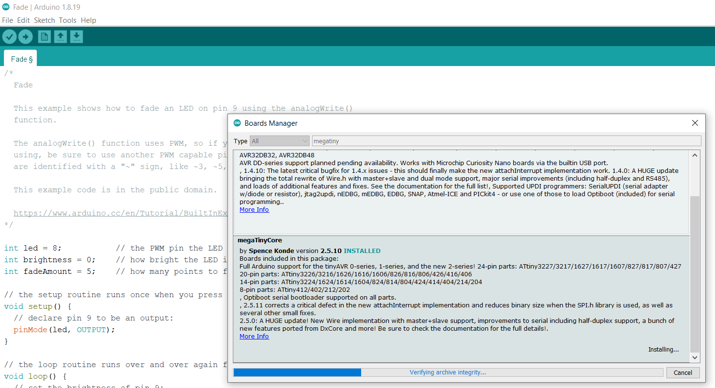
As in software, I used Arduino IDE to pprogram it. so I needed to first have the Arduino Core. From File > prefrence: click on the icon and ADD this link > http://drazzy.com/package_drazzy.com_index.json. Then from boards manager type megatiny and you will find the Arduino core we need megaTinyCore by Spence Konde
Then make sure the settings are as follows, but I think I just used the default values for most od them except for Programmer, choose SerialUPDI SLOW
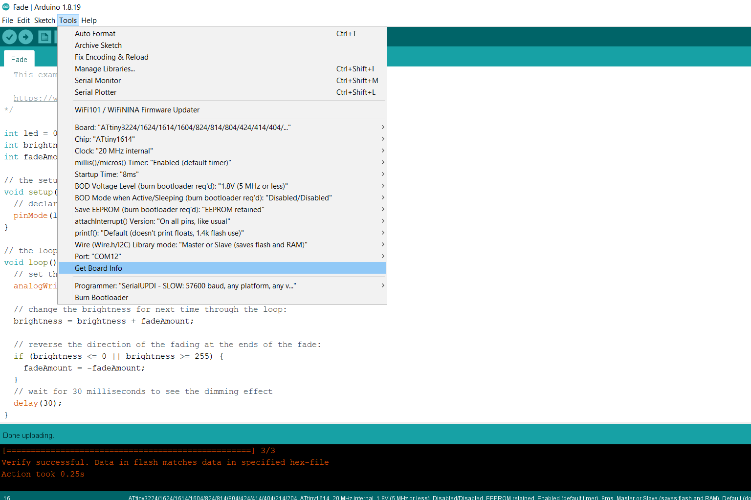
Finally ran the fade code which already exsits in Arduino examples and just changed the pin number to the one I am connecting the LED on which was 0, Here is the code I used:
          int led = 0;           // the PWM pin the LED is attached to
          int brightness = 0;    // how bright the LED is
          int fadeAmount = 5;    // how many points to fade the LED by

          // the setup routine runs once when you press reset:
          void setup() {
            // declare pin 9 to be an output:
            pinMode(led, OUTPUT);
          }

          // the loop routine runs over and over again forever:
          void loop() {
            // set the brightness of pin 9:
            analogWrite(led, brightness);

            // change the brightness for next time through the loop:
            brightness = brightness + fadeAmount;

            // reverse the direction of the fading at the ends of the fade:
            if (brightness <= 0 || brightness >= 255) {
              fadeAmount = -fadeAmount;
            }
            // wait for 30 milliseconds to see the dimming effect
            delay(30);
          }
Source files:
Individual Assignment files
Arduino codeC code