Assignment:
Group Assignment:
1# Send a message between two projects.
Individual Assignment:
1# Design, build, and connect wired or wireless node(s) with network or bus addresses.
Brainstorm
Softwares:
 - MIT Mods - a great software that allows CAM software for multiple devices at the same time
 - Adobe Illustrator - a great software that allows editing and manipulating vector images
Machines:
 Adafruit RFM69HCW
 The Arduino UNO is the best board to get started with electronics and coding.
 Roland SRM-20 - it is a precision mill that can hold variaty of small endmills ranging from 0.3mm to 6mmm diameter endmills
Tutorials:
Group Assignemnt
For this week's group assignment we have used our old boards with FTDI connection to talk to each other. At first we tried my fish shaped boared to talk to Brandon's Simon Says Board however, I think somehow after connecting them both using an FTDI connection cable, we fried our Attinies.
Fortunately, my other team member, Amanda's heart shaped board was working, so we used her board to do the group assignment. In this Group Assignment we have used Amanda's board and reprogrammed it so that whenever it takes an input it blinks an LED.
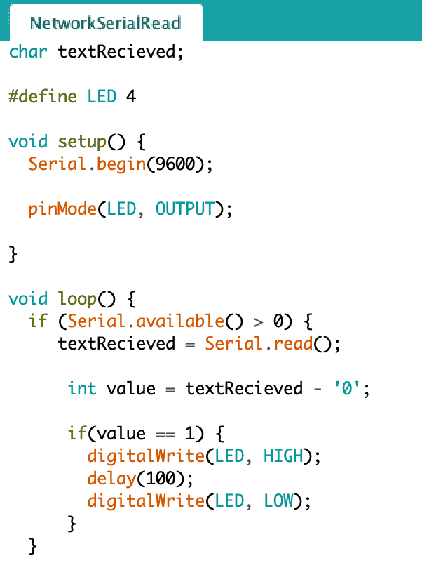
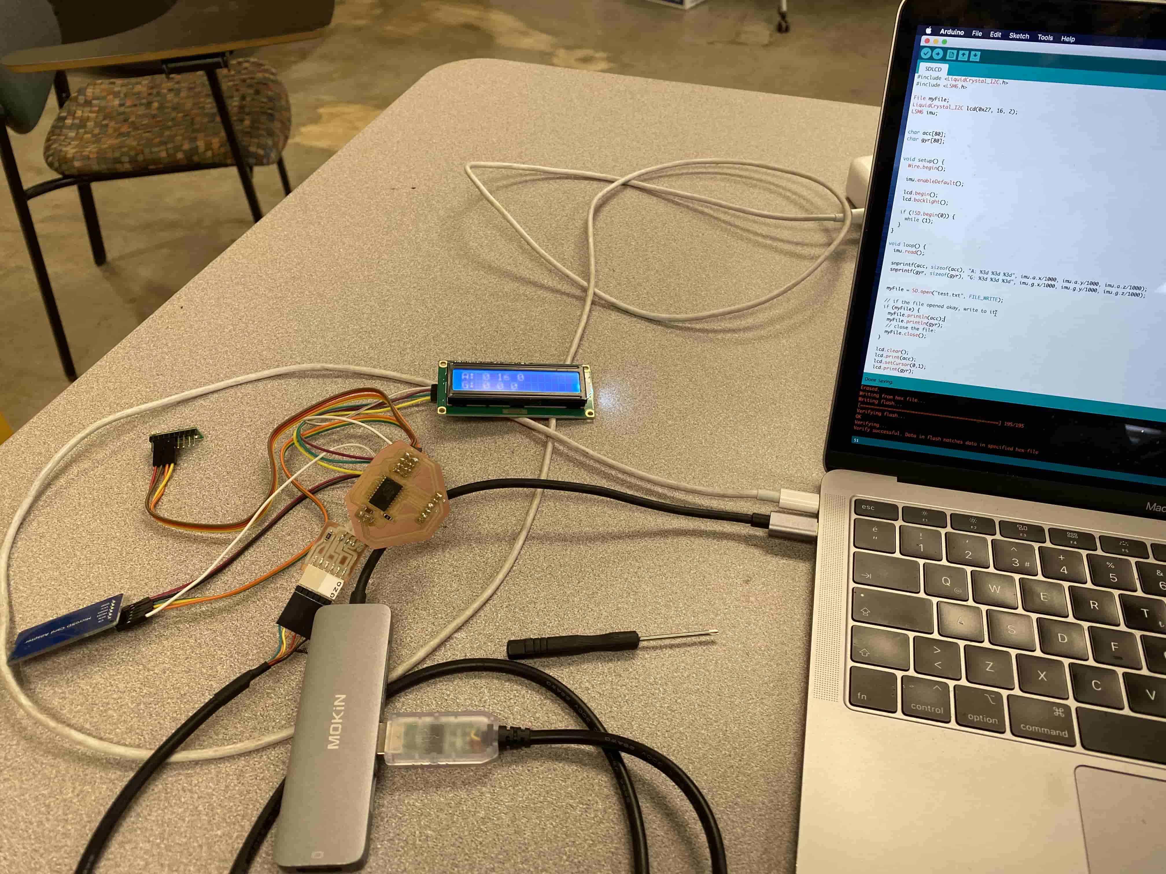
We have used the Serial Monitor in Arduino IDE to check if the board is working before connecting it to the other Team's board. We have then connected both of the boards and used one of the buttons there to turn on the LED for 0.1 sec on Amanda's board. Moreover, we have also made a new code where Amanda's board turns on a servo motor on the other board.
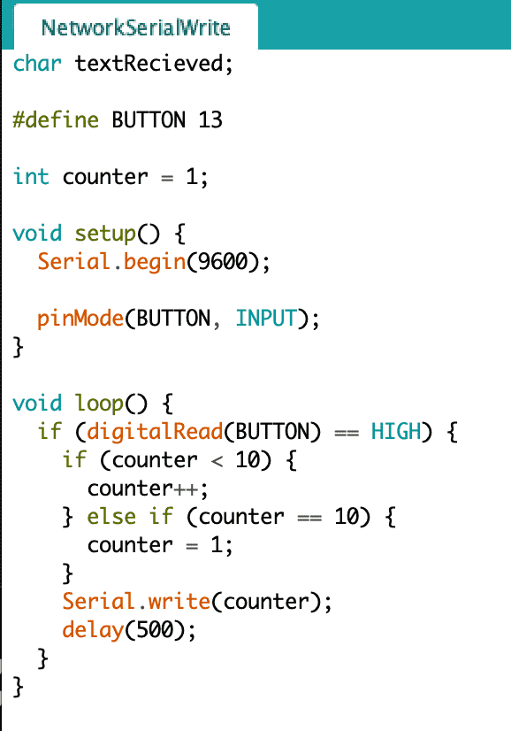

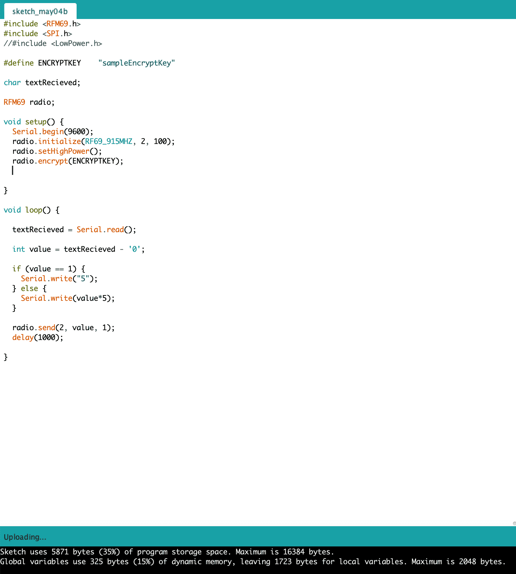
The way our codes worked is by sending a text in between two boards and interpreting it to do set things. For example in the first code I posted, our board recieves a text, which we assume to be number 1. Assuming it is number 1 that is sent through the Serial Connection, that means our board will get char "1" So we need to convert this to integer so we can use the if conditional. However if you were to do "int value = charText" then it will fill value with the ASCII value of the charText. instead, we know that Arduino is C based language and in C based language the difference between a string and an integer is that strings/chars end with 0. so if we were to delete the 0 at the end it will turn into an integer. Hence, by doing that we recieve an integer from the Serial Connection. After we get that we check if it is equal to 1 and if it is then we blink the LED for 0.1 seconds.
Individual Assignment
For this week's individual assignment I wanted to do something different then the Group Assignment we have done. In the group assignment we have used Serial Connection using FTDI connection however, I wanted to do wireless connection. For this I have used Adafruit's RFM69HCW module.
Apperently, there used to be a library called Low Power library that allowed Attinies to work with Adafruit RFM69HCW however, I did not know this till the day before Wednesday. Initially, I have started experimenting it on Arduino Uno's, I went into the Tutorial site I have linked above and started looking on how to wire the Adafruit RFM69HCW to an Arduino uno. After learning that I have moved on to how to program it. Unfortunatelly the library does not exist on Arduino IDE, so I had to manually download it from the same tutorial.
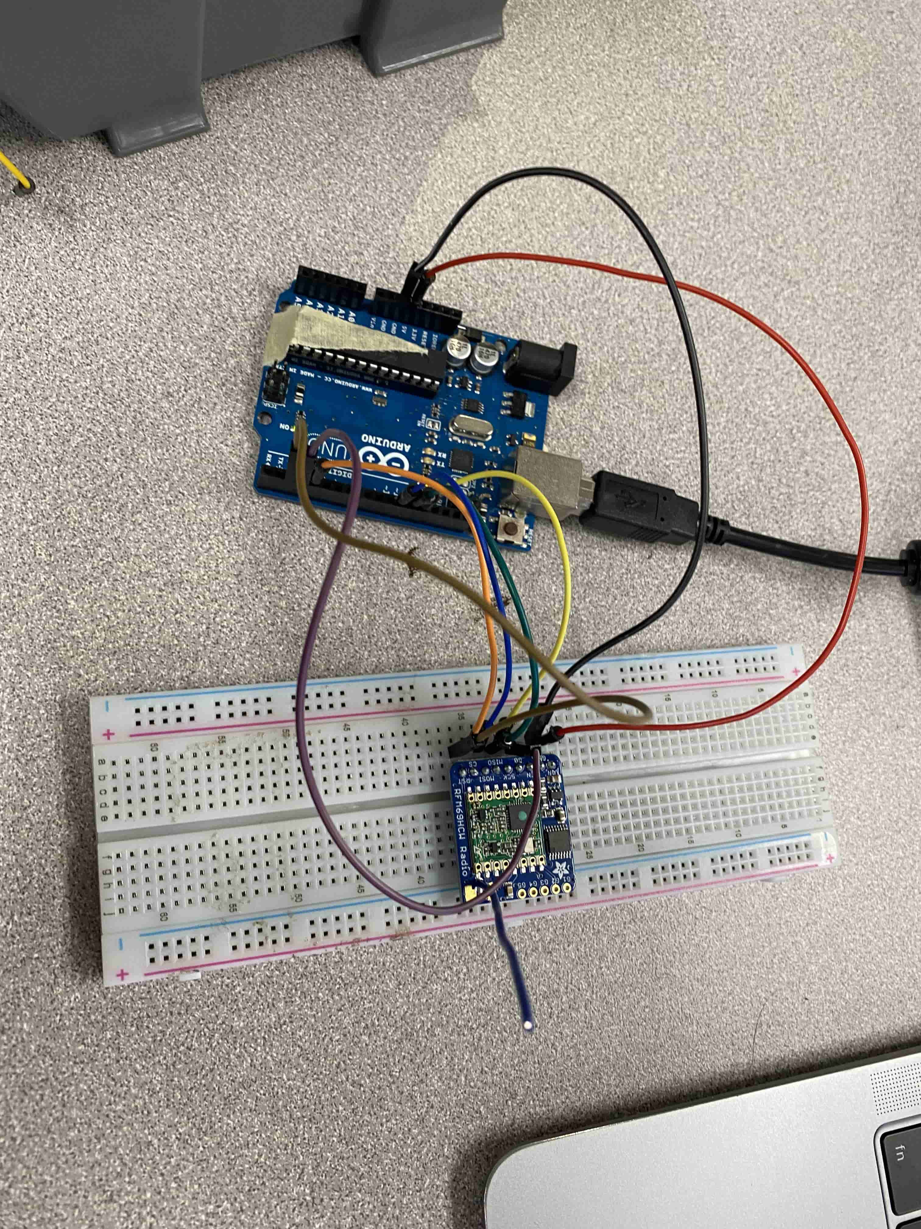
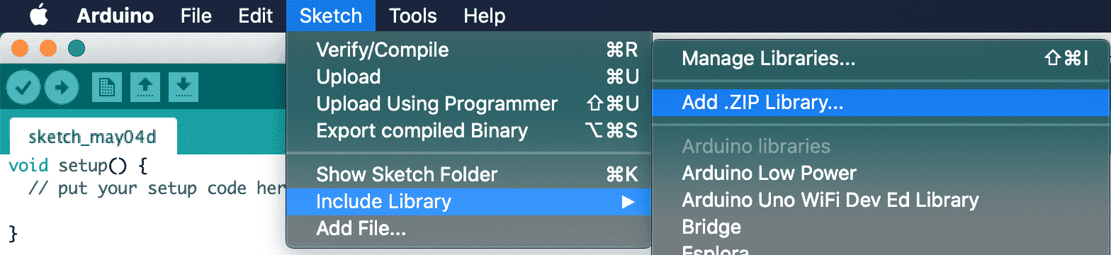
After wiring the Adafruit RFM69HCW radio transmitter to Arduino Uno, I have downloaded the library for it manually using the add library with .zip format option in Arduino IDE.
After adding the Library, I have used the example code for Arduino Uno. At first I have tried the Transmitter code and checked how it works. Fortunately the code was really clean and easily understandable.
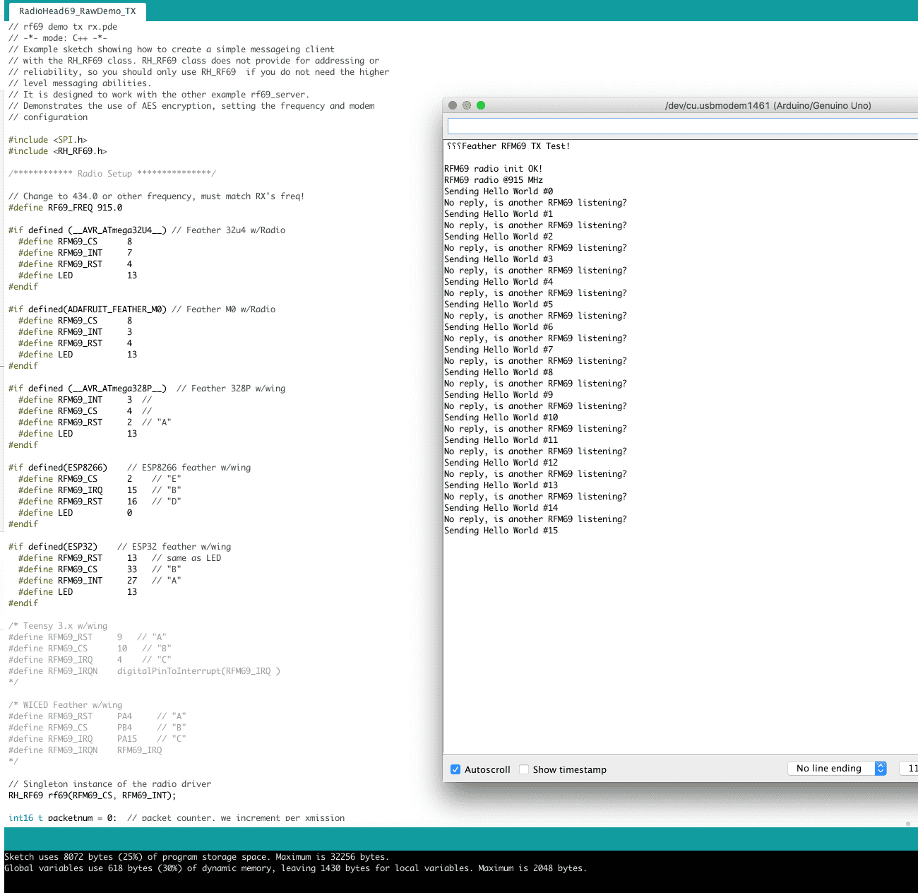
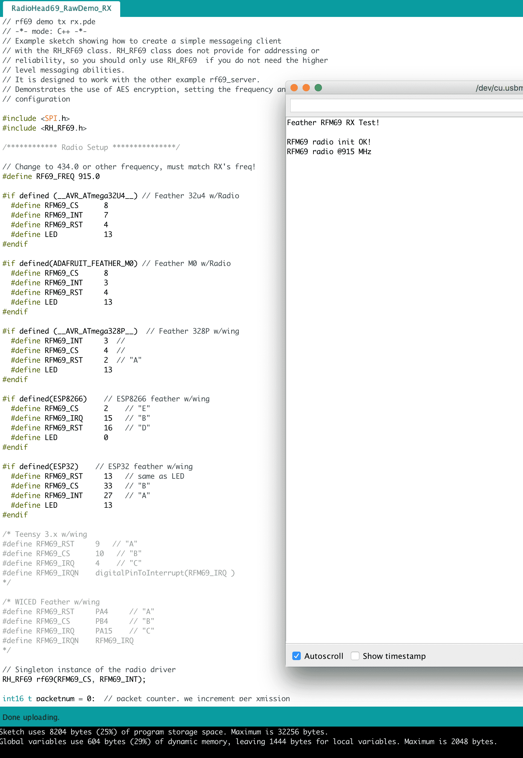
In the first part of the code, it checks which type of controller you are using and according to that you place you pin numbers. The reason to this is because some of these pins require internal interrupt pins. I have also checked how does the reciever works too.
After playing around with it, I tried to make two Arduino Uno's with Adafruit's RFM69HCW radio and try to transmit and recieve.
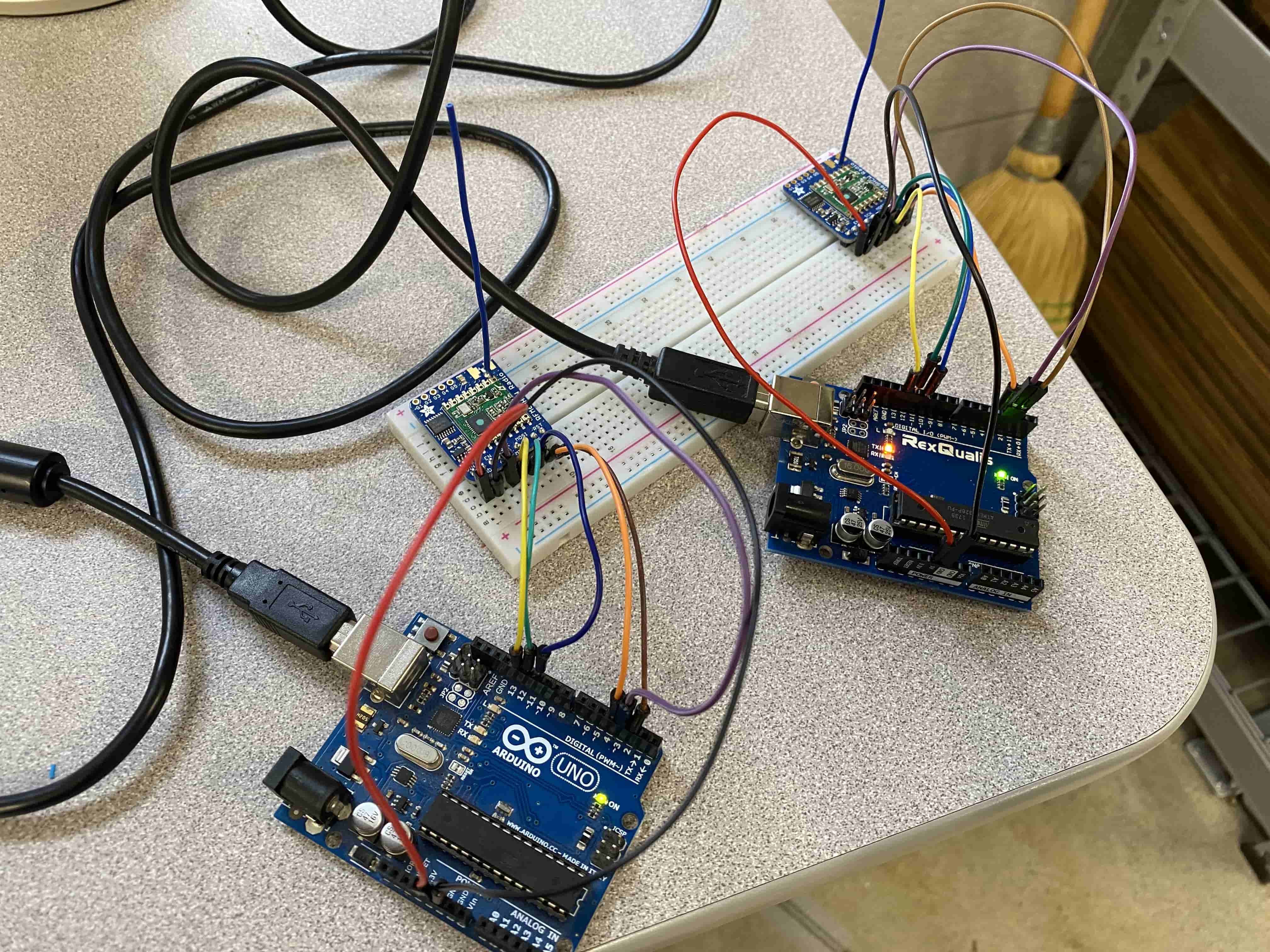
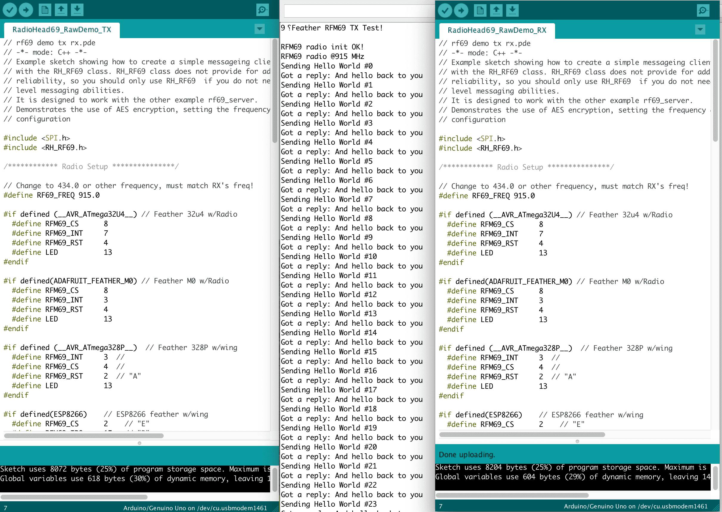
I have uploaded the codes on the screen seperately to each of them and then ran them together. Because Arduino IDE, Serial Monitor can connect to only one Arduino Board at a time, I have uploaded the Transmitter Code last. According to the code it says that the Transmitter sends "hello world" and the reciever recieves that hello worlds and echo it back. As you can see that what happens in the Serial Monitor.
After finished playing withArduino Uno, I have moved on to designing my own board. I was still really suspicious of the RFM69HCW, so I also added an FTDI connection.
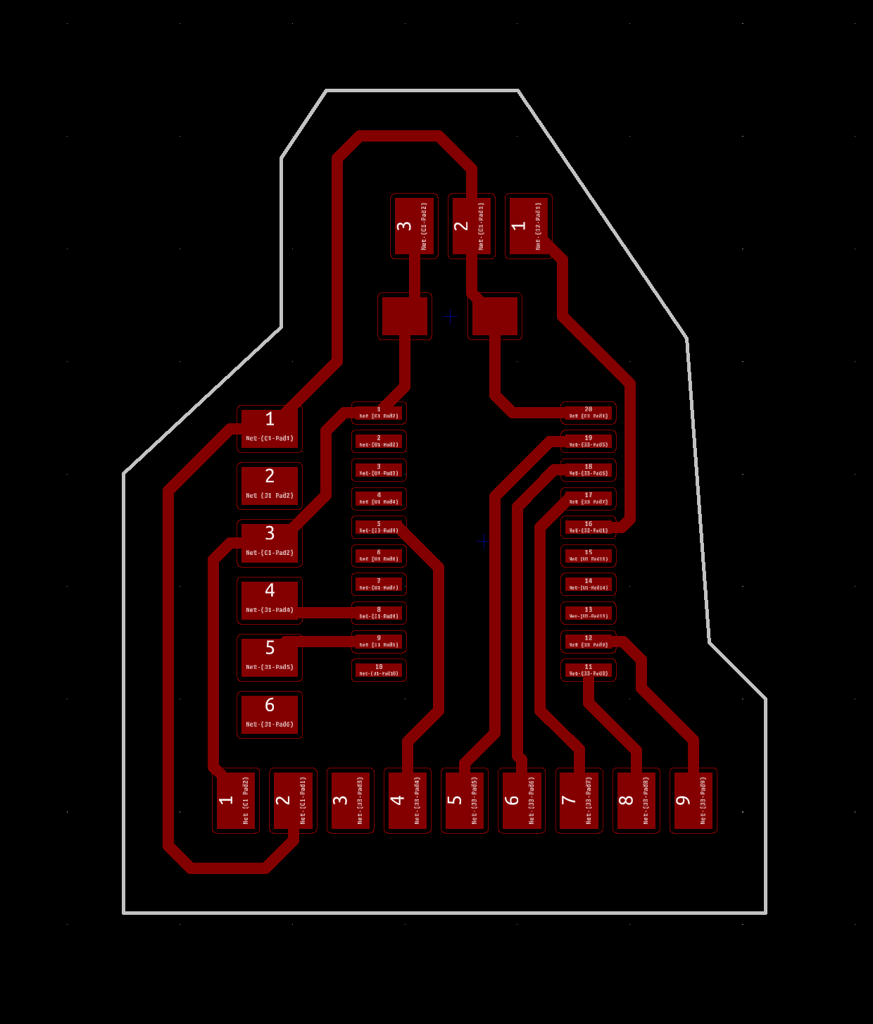
After Designing my board, I have milled it out and soldered the RFM69HCW on it.
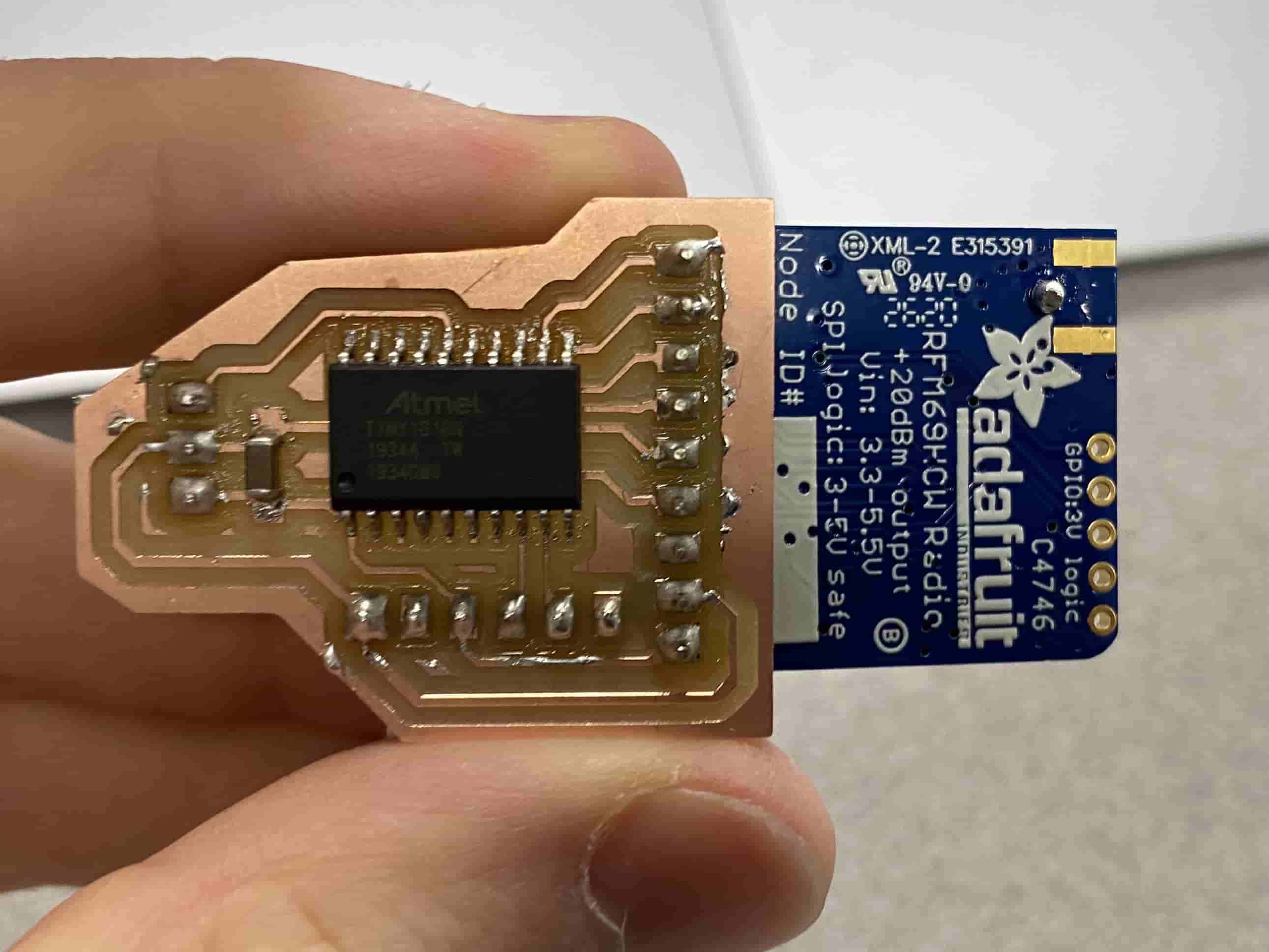
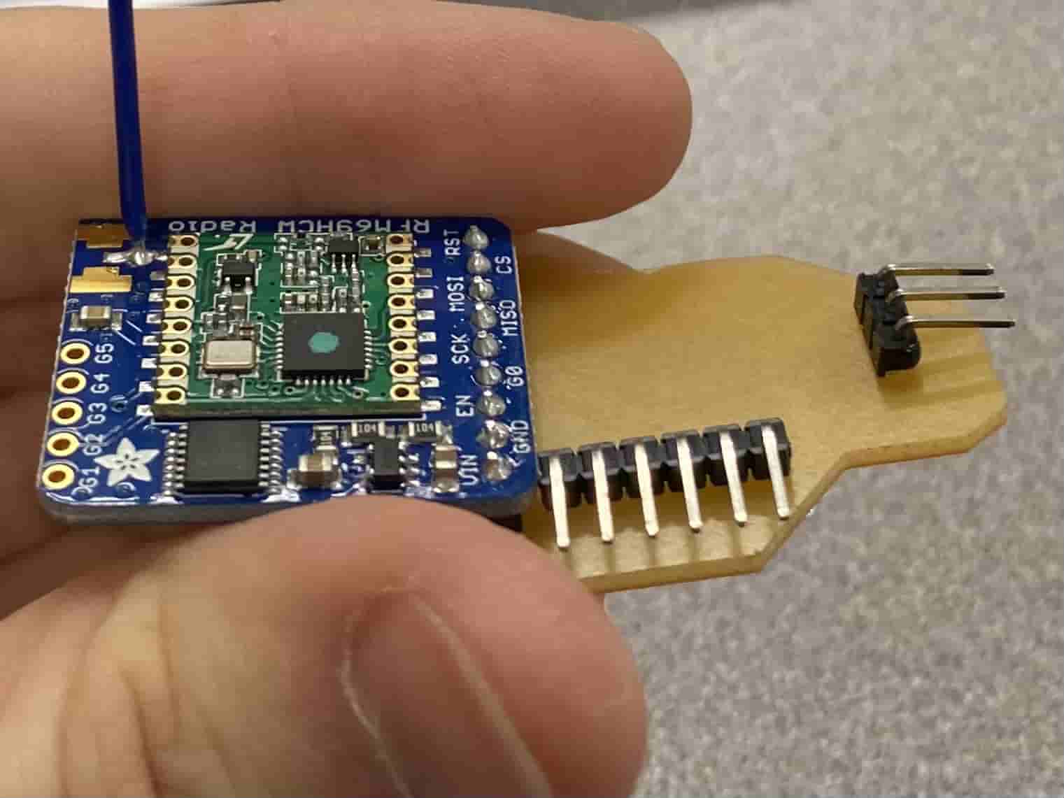
On this board, I do not have any buttons nor LEDs, the only device on it is the RFM69HCW. As you can see the RFM69HCW is upside down. The reason to this is because I had to solder the headers to the RFM69HCW first. The reason to this is because I wanted to test it out using an arduino uno. However, because of that I was not able to put it upside up. The headers came out from the under side of the PCB which is the arylic side of the PCB.
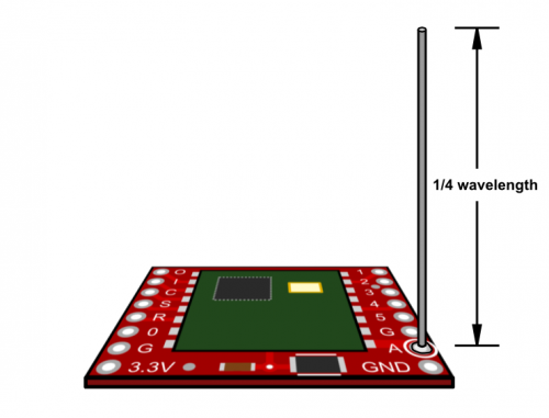
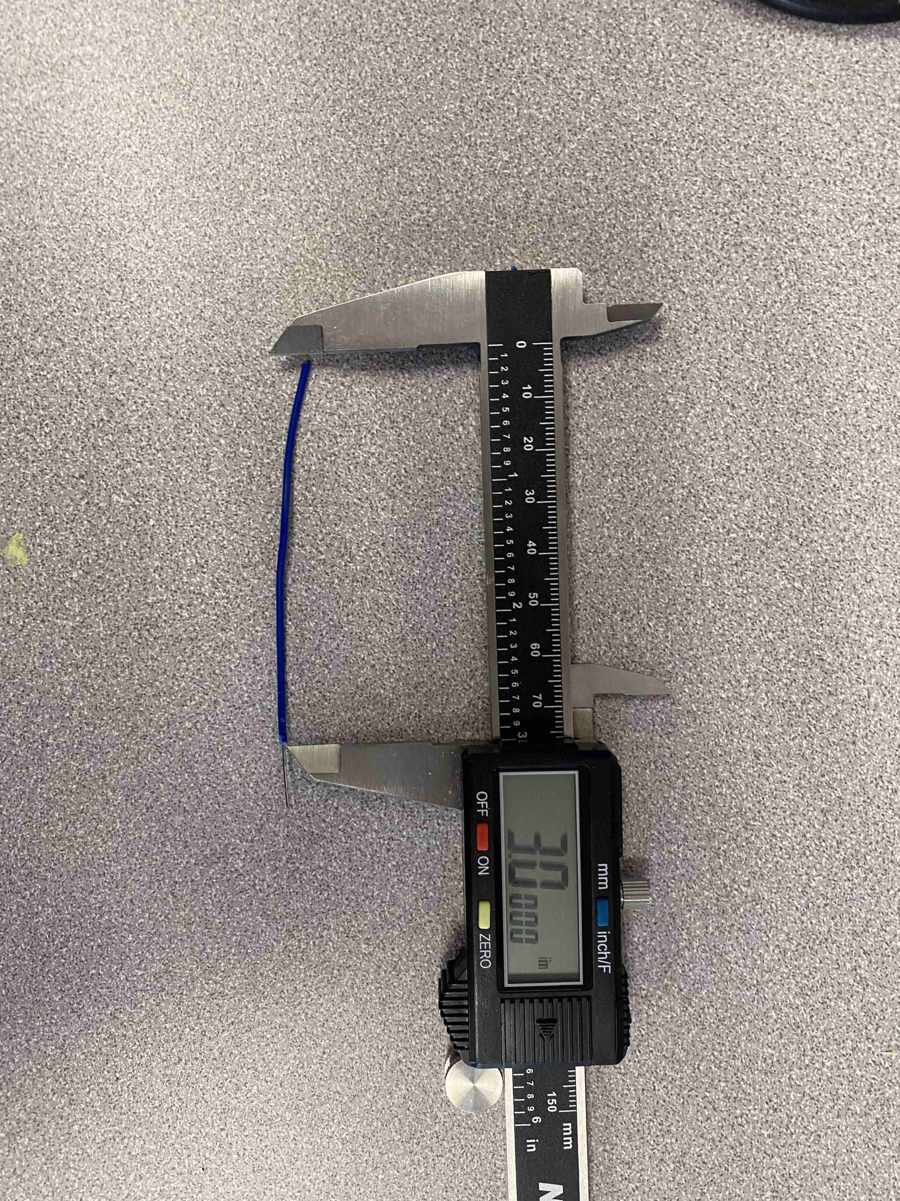
Moreover, from the photos you can see that a wire is coming out of the RFM69HCW. That wire is a Antenna with a length of 3 inches. The reason to this is because I wanted to achieve a wavelength of 12 inches with a frequency of 915 Hz. To achieve this I followed the tutorial and found out that 3 inch long antenna gives the best results.
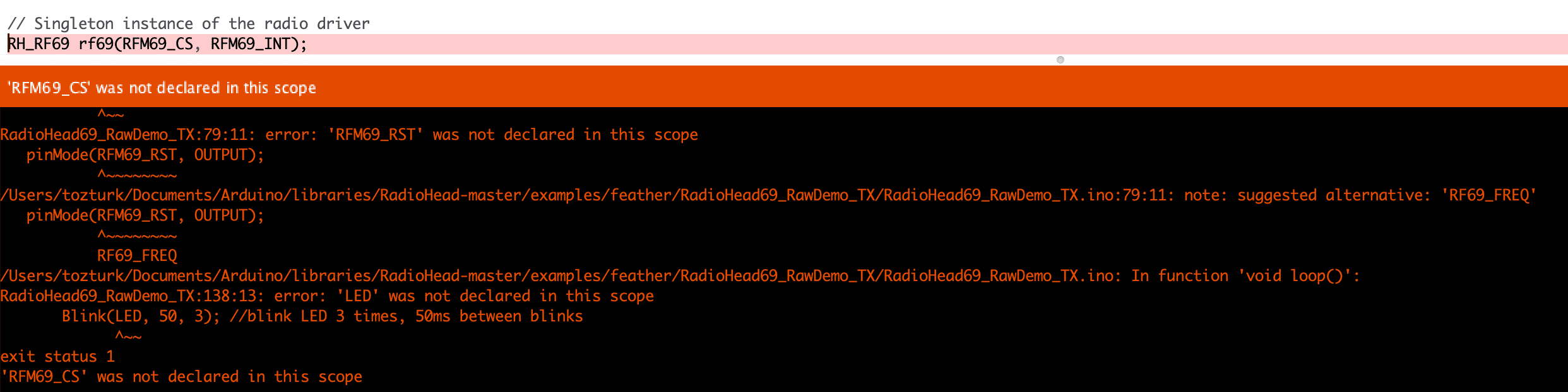
After preparing my board, I tried to upload the same code that worked on the ARduino Uno, however, I can never be lucky and get it done in the first try. so yeah it gave an error.
After days of research, downloading 5 different libraries, trying multiple lines of code, I was finally able to find a library that kinda works with my board. I have hand written my code looking to an example code from RFM69_Low_Power Library.
I was aable to upload my coe to my board, but unfortunately I wasn't able to test it out with an Arduino Uno because the library I used, is different than the initial library. Hence, I was not able to connect them. Then I gave up and treid to just use the Serial Connection from FTDI pins however, once I tried to upload my code, my MCU stopped working and started giving UPDI ERROR.