FINAL PROJECT - GameBoy : Aliener
Final Project Slide and Video
Here are the Final Project Slide and Video.
Presentation Slide:
presentation Video:
Final Project Info
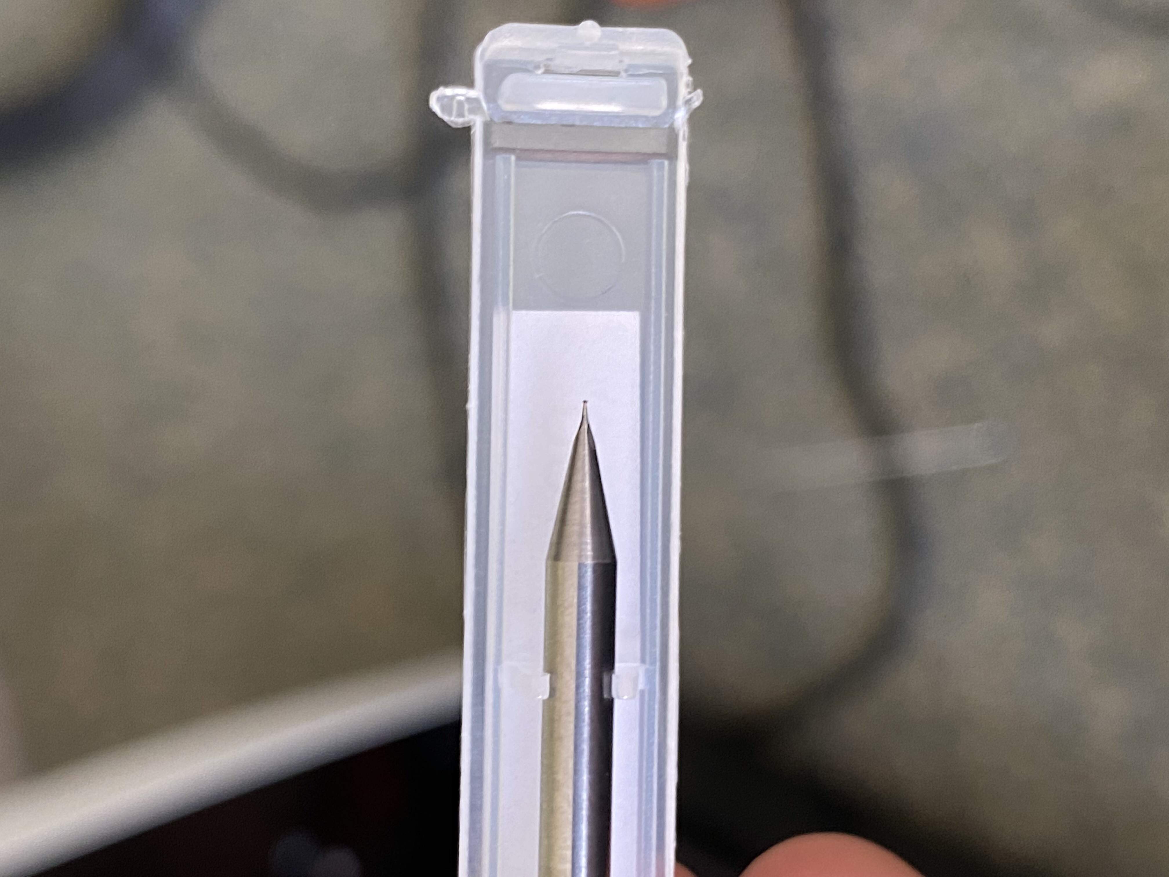
Throughout the first two weeks of fab academy I had many ideas on what to do. Most of my time, I was having trouble with selecting which one of my ideas to do. My initial ideas were either making a Metal 3D printer where the 3D printer lays some composite sand and some metal powder in specific layouts in a rectangular stone container which that furnaced to melt the metal in a composite sand mold made with the composite sand dust. My second idea was to create a smart breadboard allowing you to see the circuit you are creating in real time by rendering your curcuit on an LCD display below the breadboard. My third idea, the one I went forward with, was making Smart Glasses. A glasses that provides you with Augmented Reality and helps the user with their daily life. "It is easy how to calculate how to go to moon, however, it is hard to manufacture the vehicle to take you there". For example, before inventing tungsten endmills, achieving the ultimate power of Titanium was almost impossible. However, after inventing new manufacturing methods, we were able to manufacture incredible machines such as the SR-71 Blackbirds or the Apollo program. All my ideas seemed really challenging due to lots of missing tools or missing knowledge on my side. Hence, I have selected to go forward with the Smart Glasses. After researching on it for few months, I had a picture of how it will look in my mind. however, towards the mid-semester, I had another idea of making a gameboy. If you were to go to the Week 11 - Input Devices. You can see that I already made a gameboy. This inspired me to make an even better one which can upload multiple games from an sd card. However, after doing some research I have figured out that it would be too hard for me to do it in 5 months. Hence, I reverted back to the Smart Glasses. On the last weeks of FabAcademy, I have started working on manufacturing my Smart Glasses. After some research I figured out that I need to use an ATMega to run the software needed for the Transparent OLED I am using. However, due to shortage in the Microcontroller market, I was only able to order ATMega32u4-MU which has 40 pins that are underneath the microcontroller. As proof of concept I first designed a simple board with an LED and a USB port which will allow me to prove the concept of programing an ATMega32u4-MU via USB rather than UDPI. I watched multilple videos on how to hand solder them however, I was never able to successfuly solder one. The reason to this is because in all the videos they were using professional grade PCB. However, I was using Roland SRM-20 Precision Mill to mill out a PCB which led to really bad traces, since I was trying to have pad width of 0.5 mm, and lots of groves that the ATMega can get stuck to. Hence, I had to scrap the Smart Glasses Idea too.
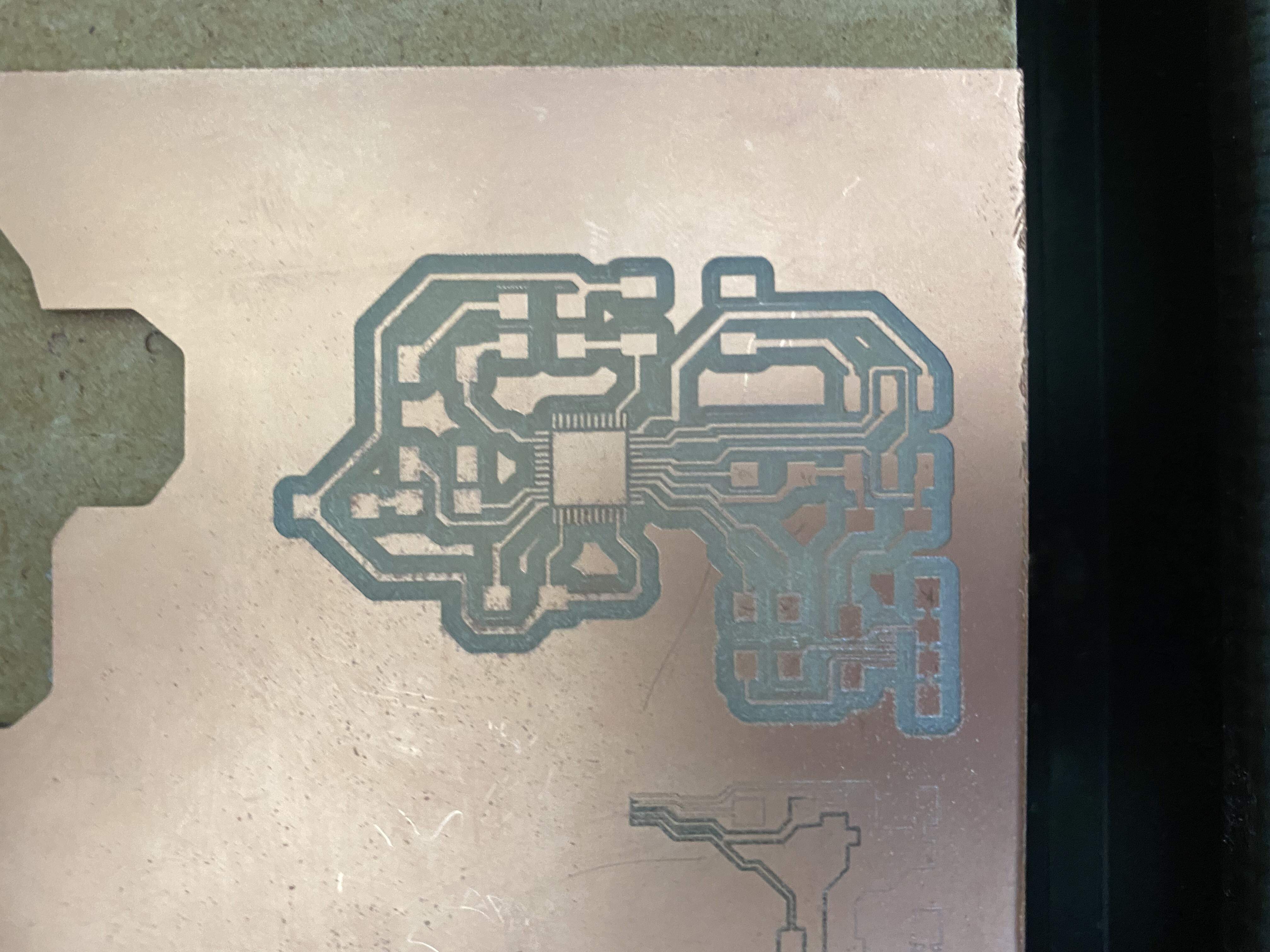
After so much work, I was still not able to get any success with it. I have decided to drop of the idea of making Smart Glasses for my FabAcademy Final Project, and decided that I will do them as personal project. Moreover I have decided that I will be using my project from Week 11 - Input Devices week as my Final Project since it already completes most of the requirments. Before, I start showing you my work, I wanted to talk about the criterias I used to select my Final Projects
Criterias:
Final Project:
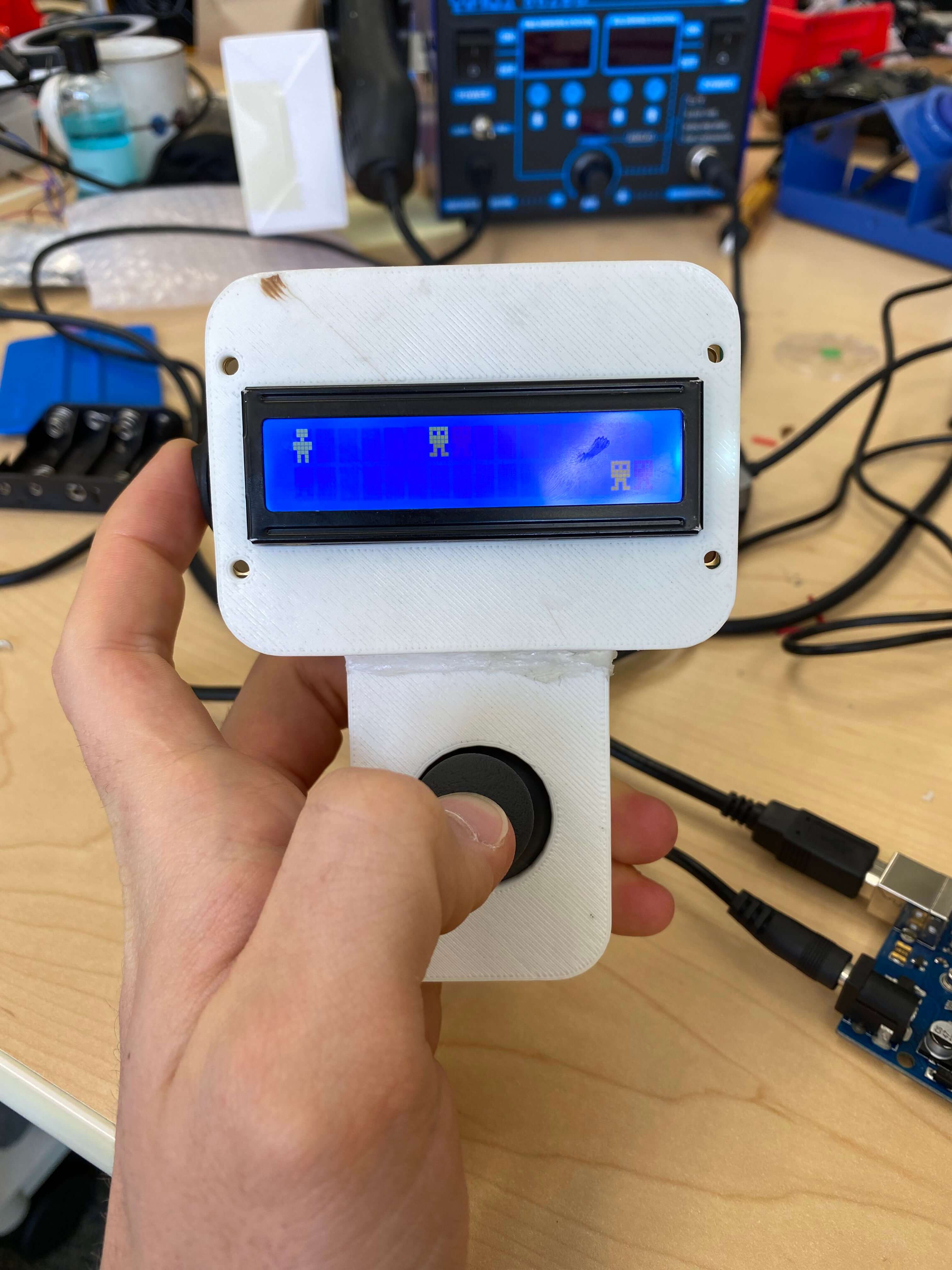
You can see most of the build process for my Final Project in Week 11 - Input Devices page. In this page I will talk about what I have done extra to complete all the requirements of having at least one type of subtractive manifacturing method, at least one type of additive manifacturing and electronics. I have completed the Additive manifacturing and electronics in week 11 - Input Devices. My name real name is Tuna. My mom gave that name to me because it is the name of a river in Europe (the Danube river) in Turkish. However, at the same time it is a really common fish in the world's most international language, English. Hence, I have a thing with creating Tuna Fish Merch on all the things I have.

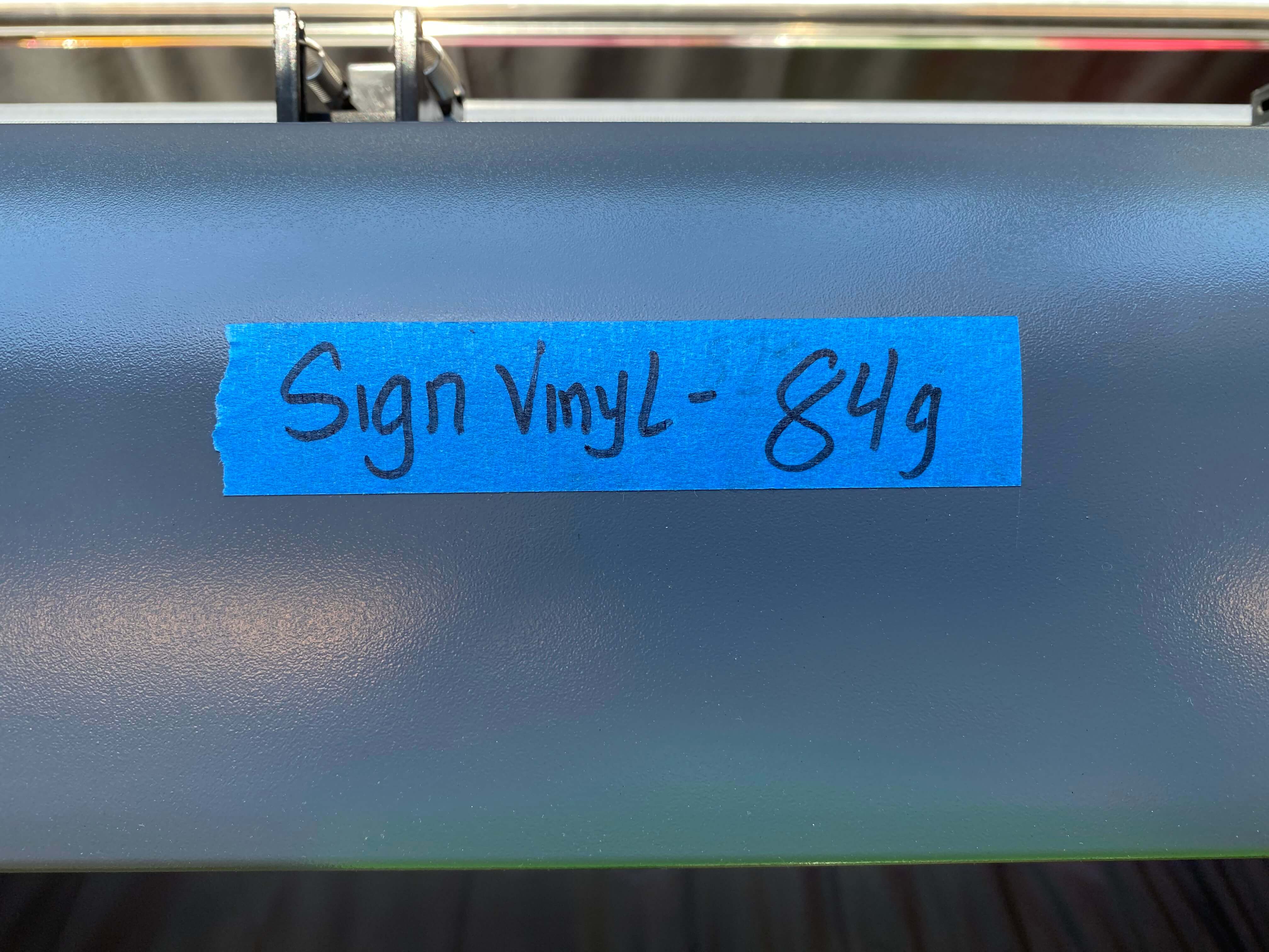
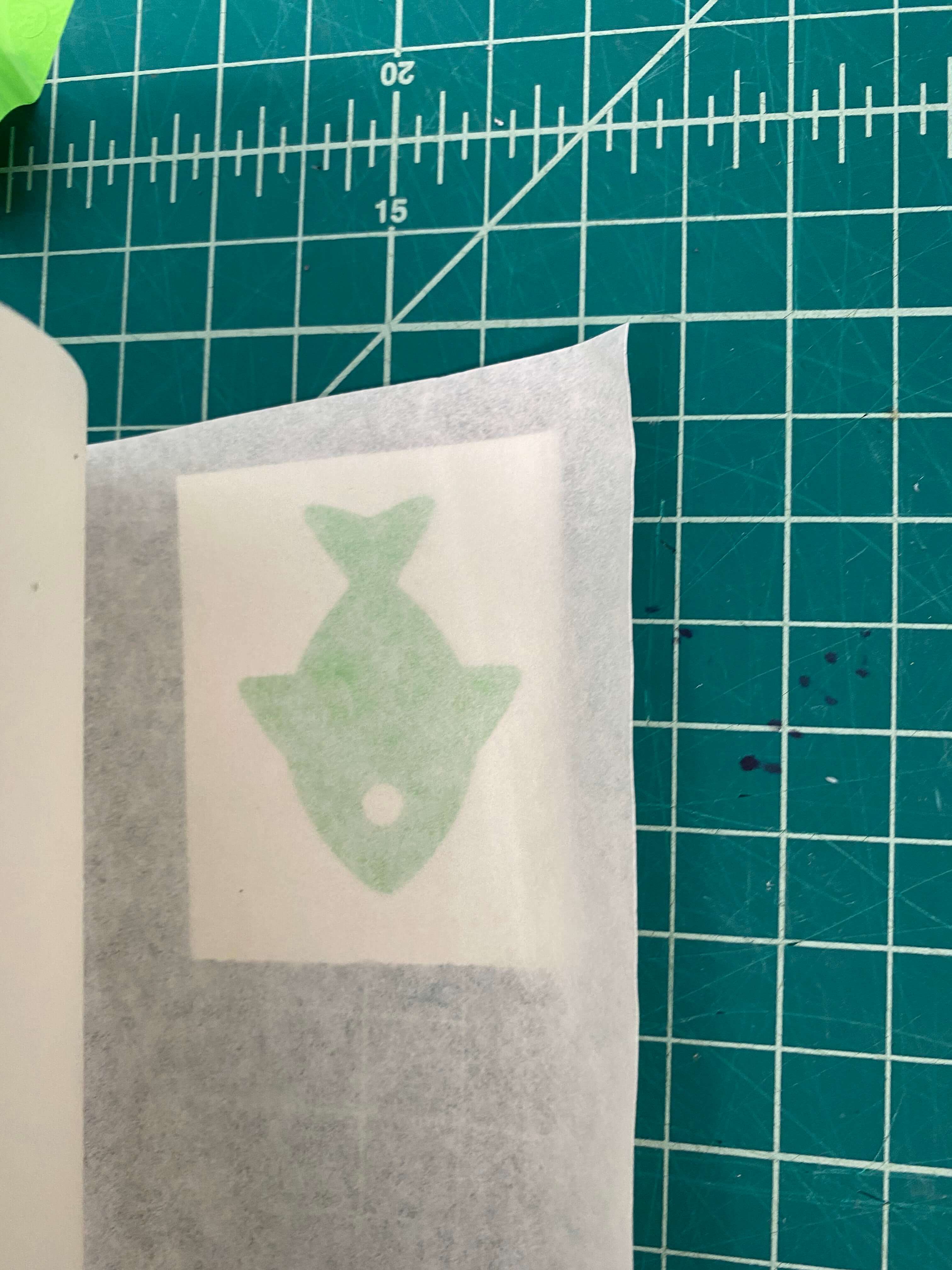
Hence, I have decided that I will be placing a fish Icon on the back of my GamBoy. For this I have used our Vinyl Cutter and I have used Sign Vinyl. First I have selected an vector image online.
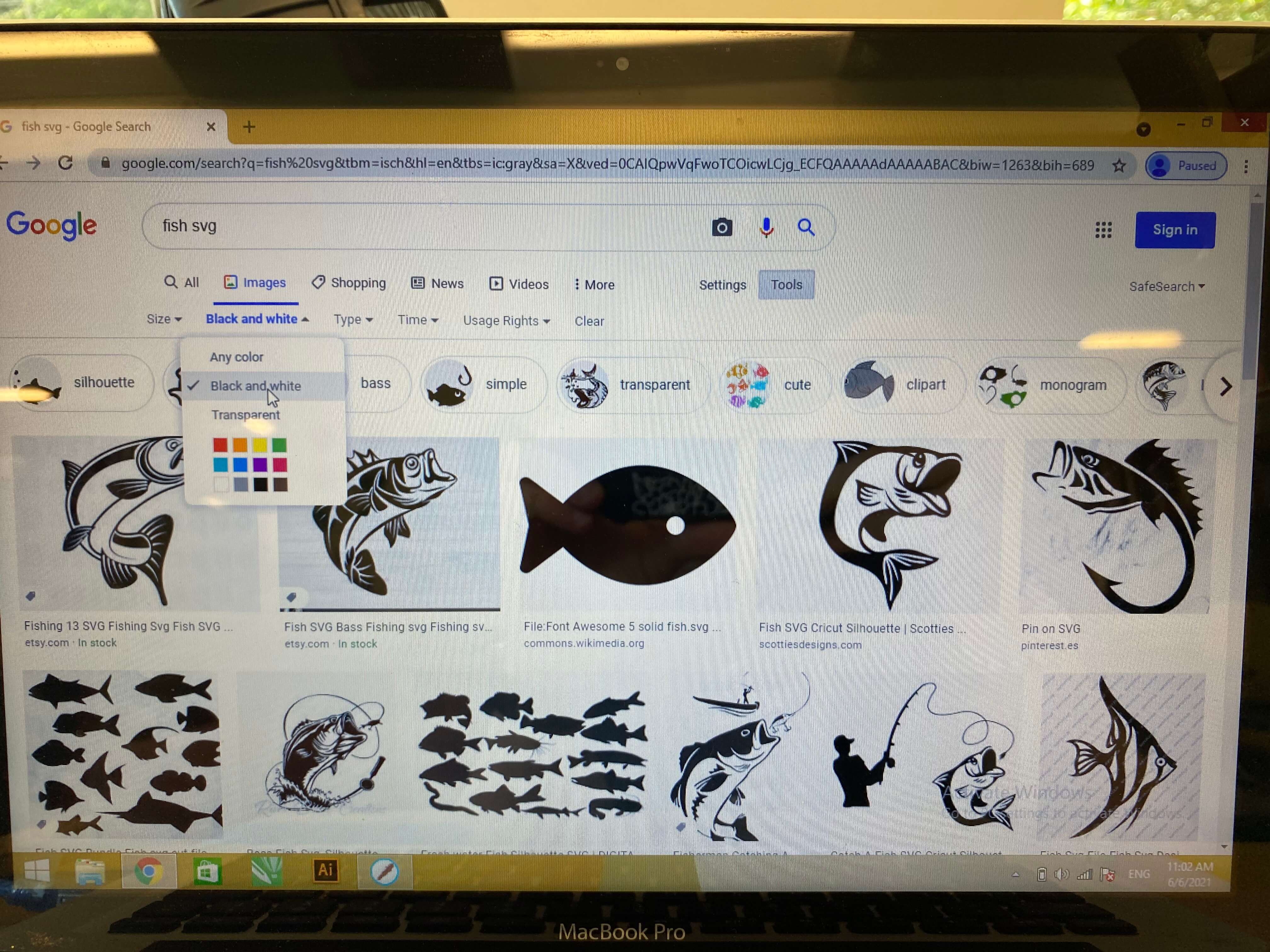
After selecting the correct image I have moved on to uploading it to our Vinyl Cutter software: "Sure it cuts!" One thing I suffered is, this software is really smart and does not like to use vector images even though it really needs vector images. Hence, instead of vector images it likes to use black and white png images that actually looks like vector images but actually is not one. Hence, I had to first go to an online converter and change that fish image from SVG to PNG. After doing that, I have went on the software and clicked the "Image Trace Button." This tool allows me to put an image as a cut file on the Vinyl.
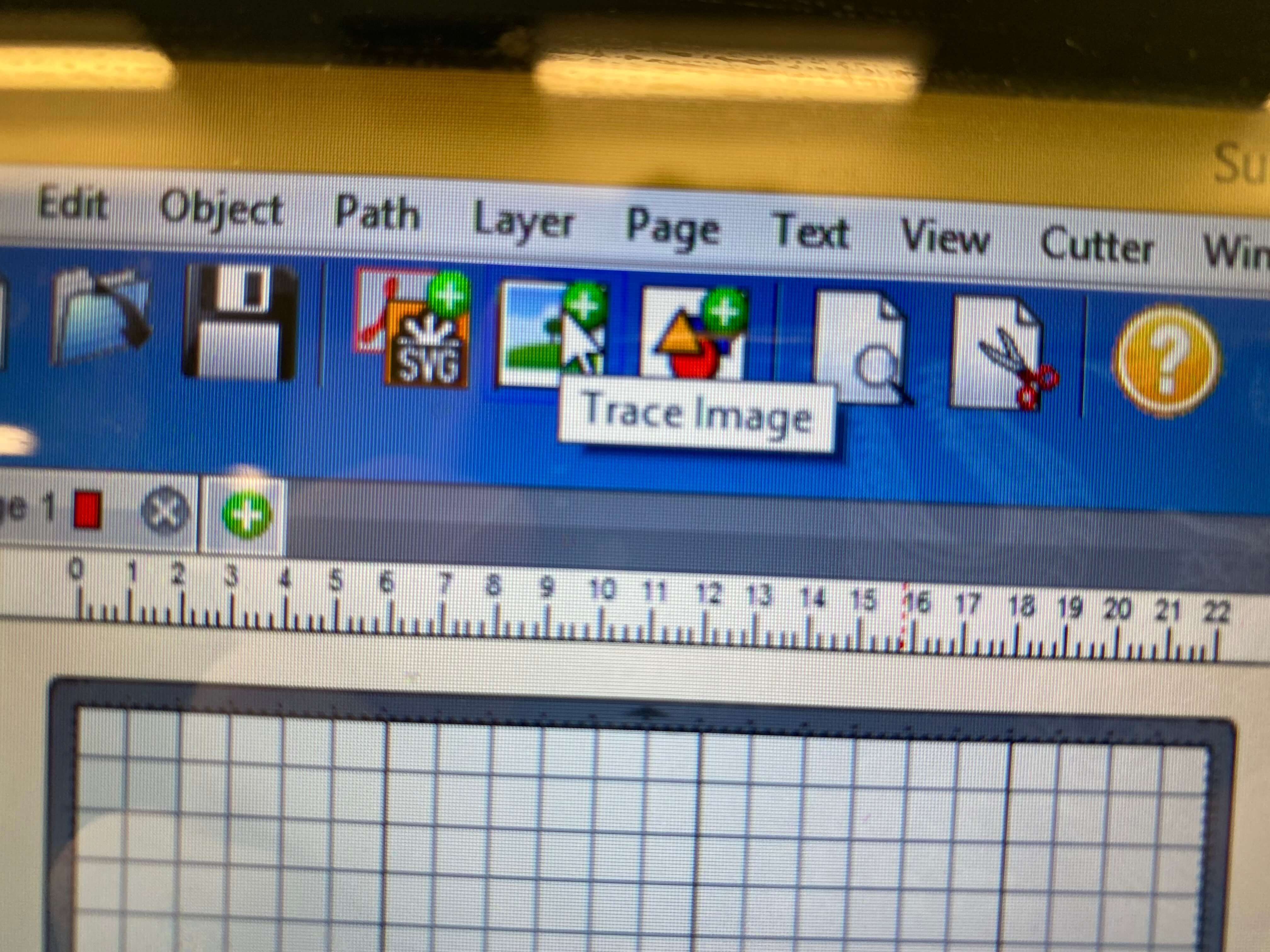
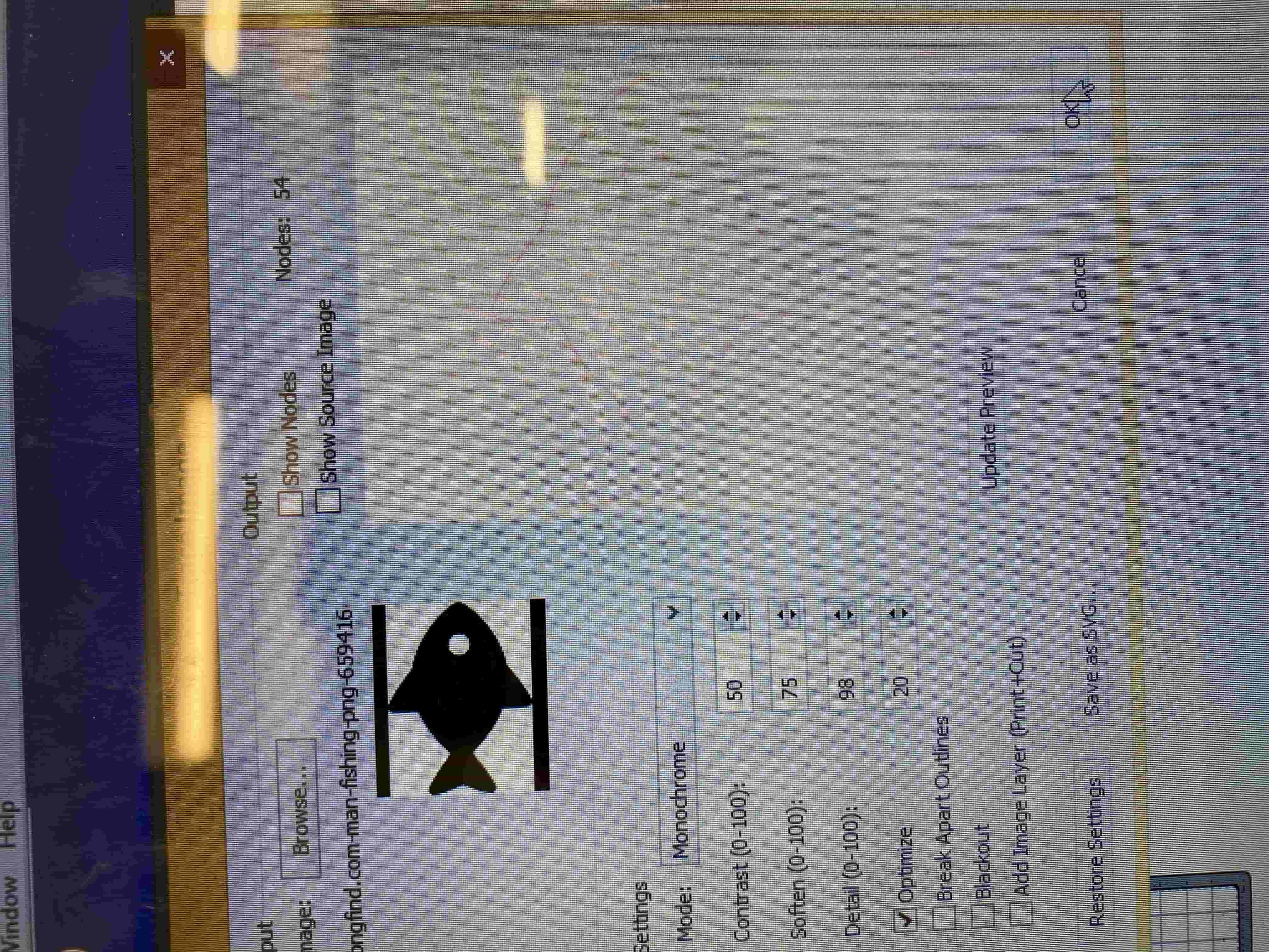
This option allows me to select and image and automatically traces a black and white PNG image for me and places on the top left corner of the software.
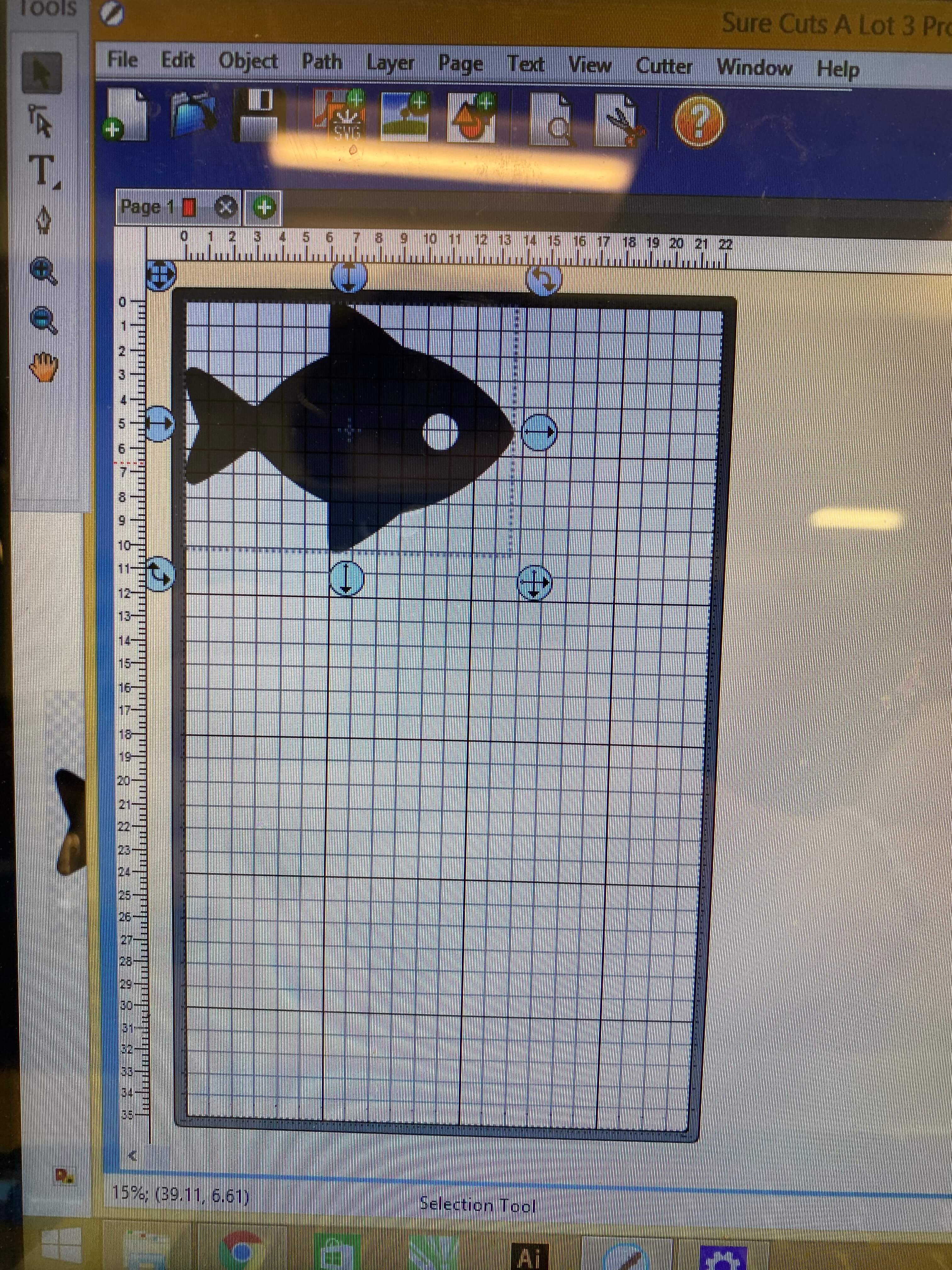
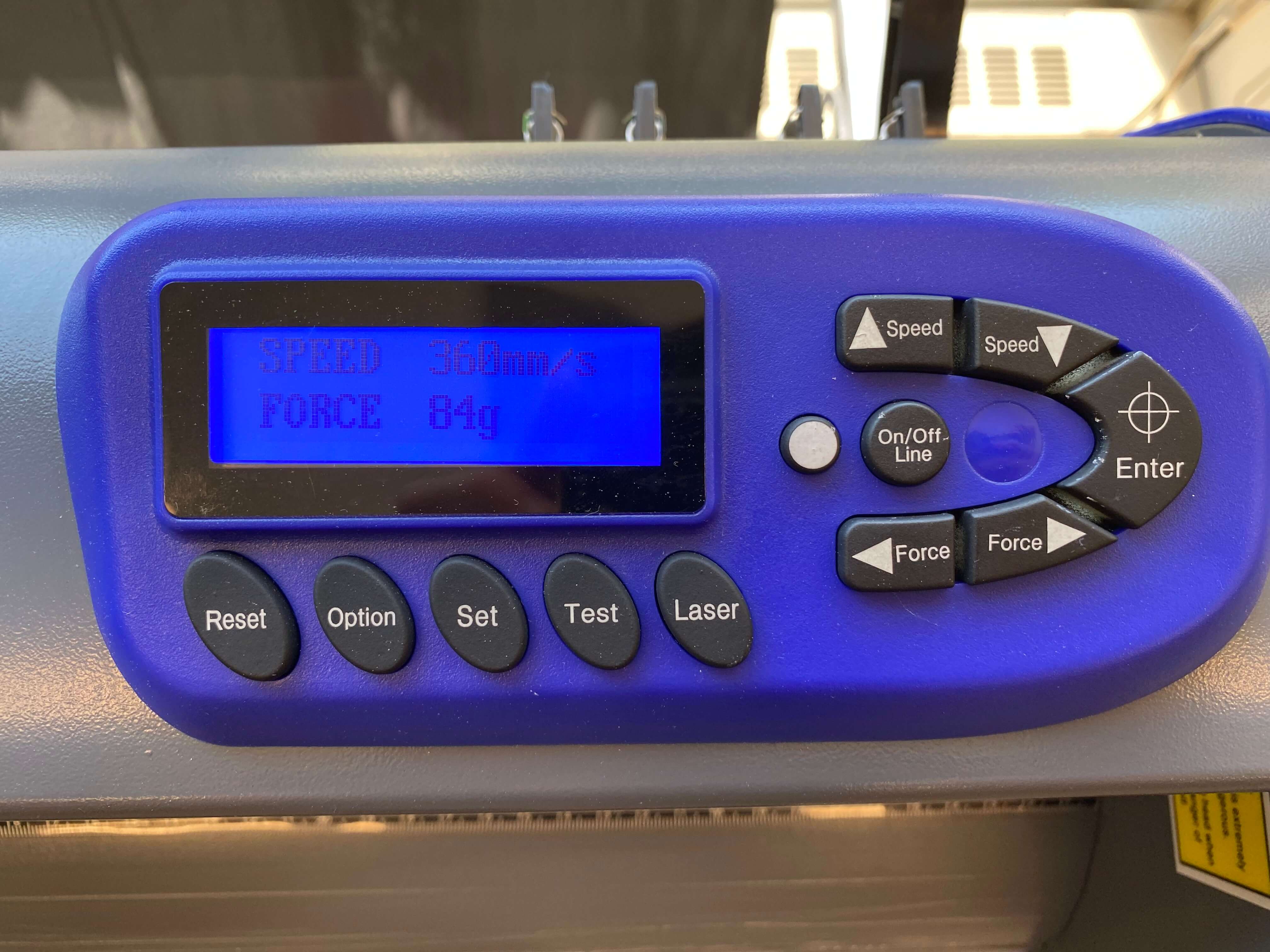
After this, I need to resize it so it fits my gameBoy. After doing then I went on the cutting process. Before cutting it however, I need to set up the machine. For this the initial step is to put the Sign Vinyl inside the machine by locating 3 rollers on the machine that goes underneath the Sign Vinyl and holds it tight. After that Using the Guides on the top of the machine I have set up the home position and the required force and speed.
After seting up everything I went on to the computer and clicked "CUT" which started the cutting process on the Vinyl cutter. It took around 5 seconds to complete. After that I cut out the viynl and cut out the aproximate area of my fish from the rest of the vinyl for making next steps easier.
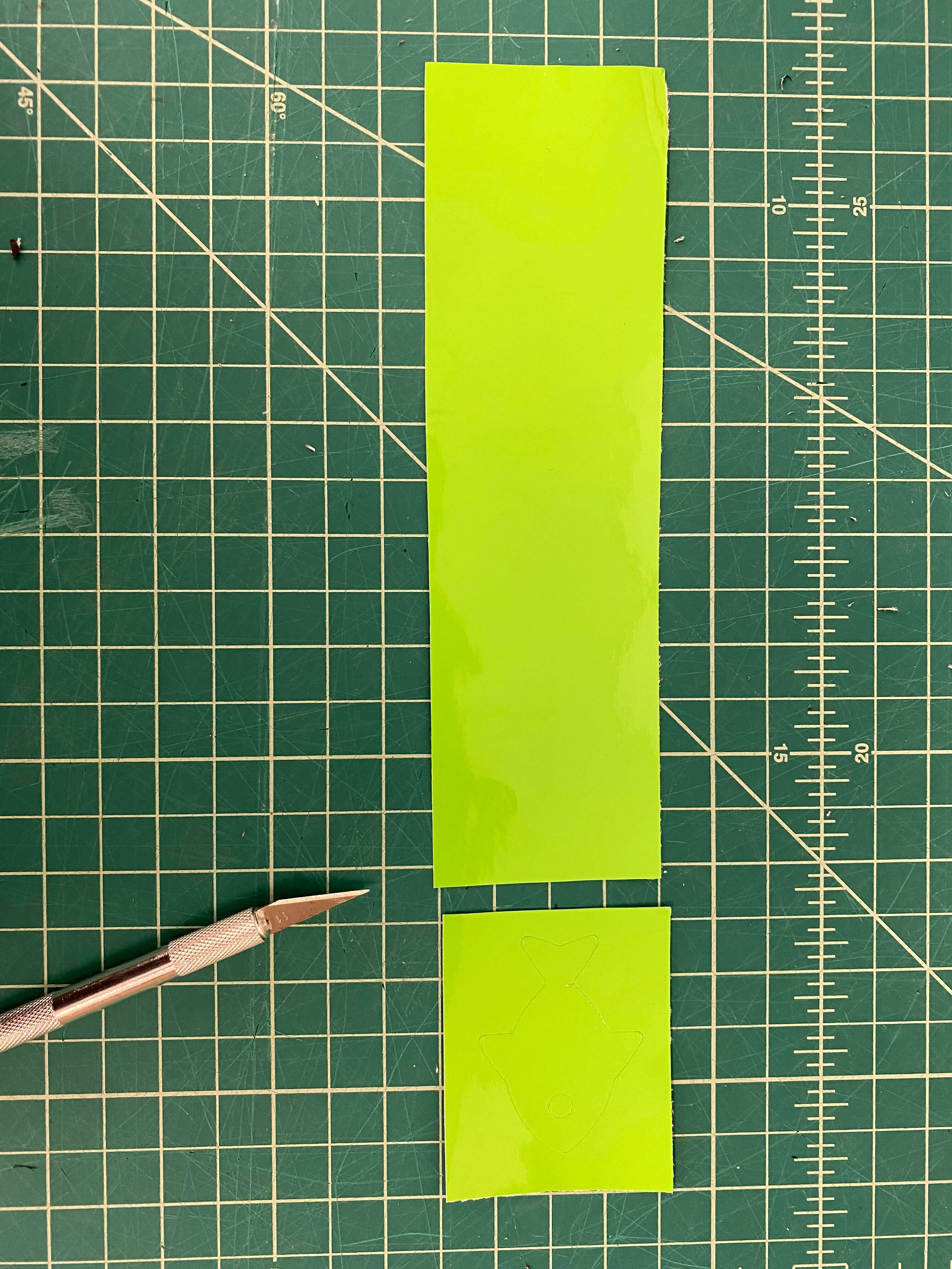
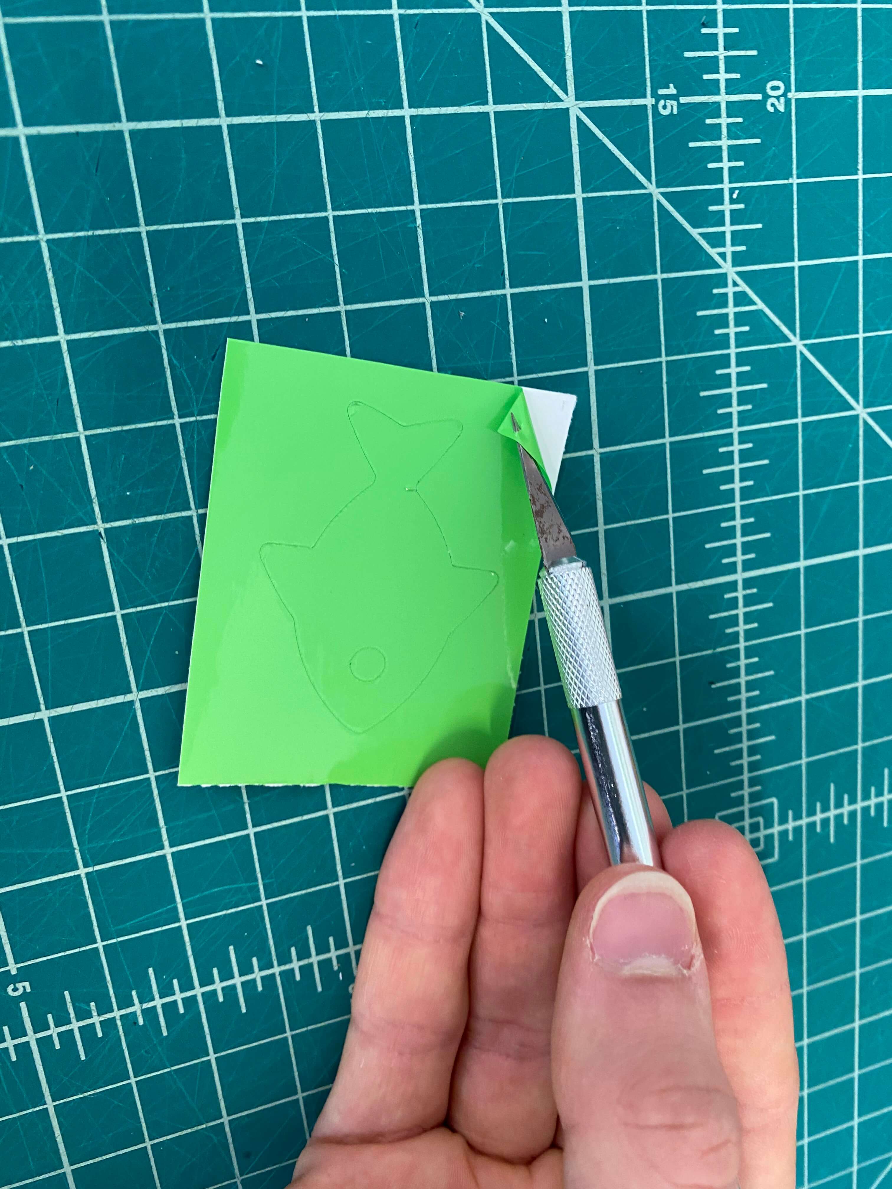
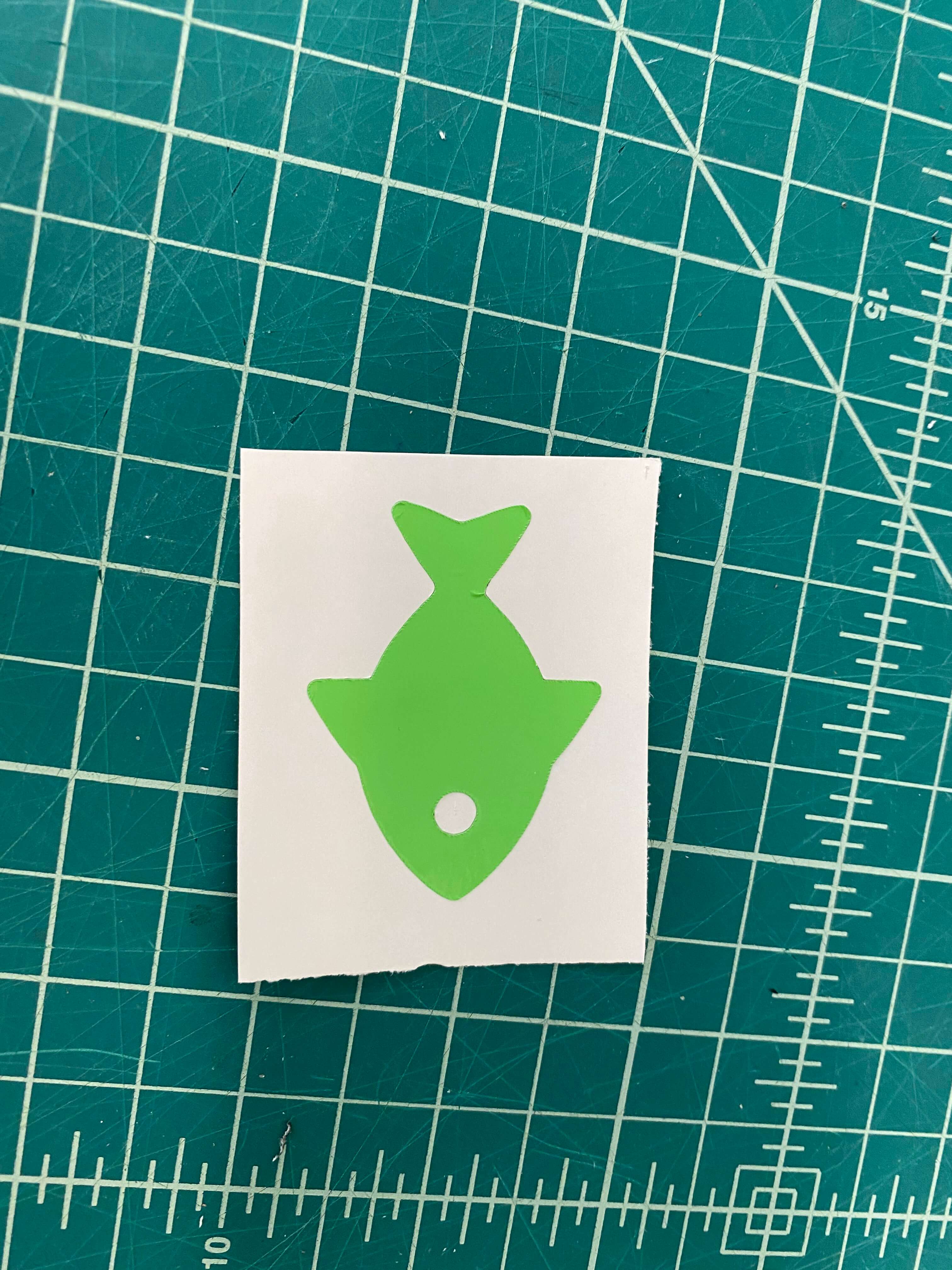
After that I have started peeling the excess vinyl. The reason I am doing this is because I want to transfer this sign vinyl to a different surface and I only want to transfer my Fish Icon and nothing else. Hence, by removing the surrounding it enables me to only interract with the shape I want to transfer.
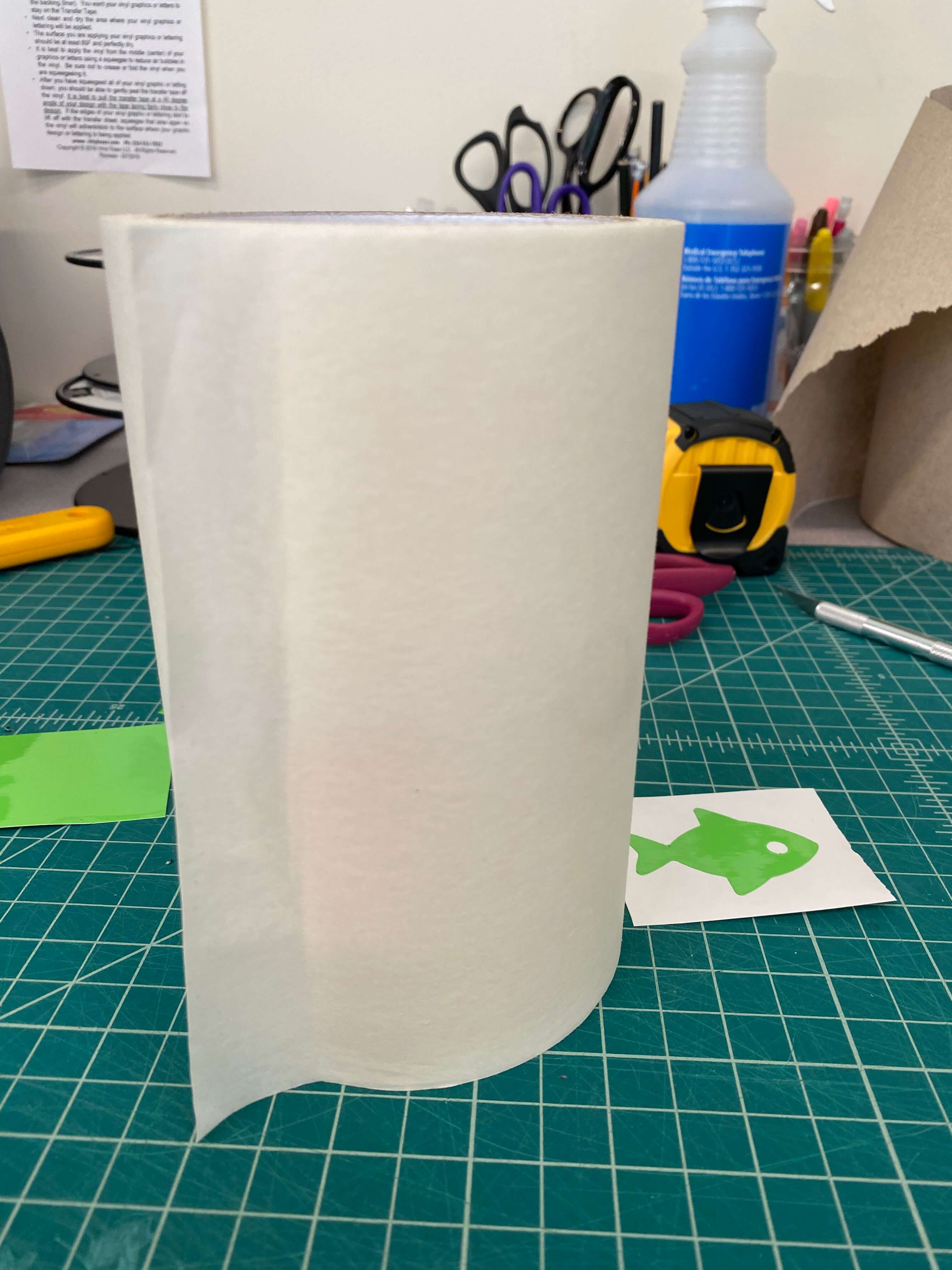
After peeling it I have used transfer tape to tape it over the Fish. This will allow me to get the fish out of the sign vinyl's paper and let me adhere it to a different surface. However, the force between the sign vinyl itself and its paper is pretty strong so I need to use a credit card or something like that to squeeze out all the air bubbles between the transfer tape and the sign vinyl so I can easily peel it off the sign vinyl paper.
After completing this process now I peel the transfer tape off the sign vinyl paper and this allows me to get the sign vinyl itself on the transfer tape rather than the sign vinyl paper. AFter that I have paste it on the back of my GameBoy and again using a credit card I have made it sure that they both stick to each other and that there are no air bubbles left.
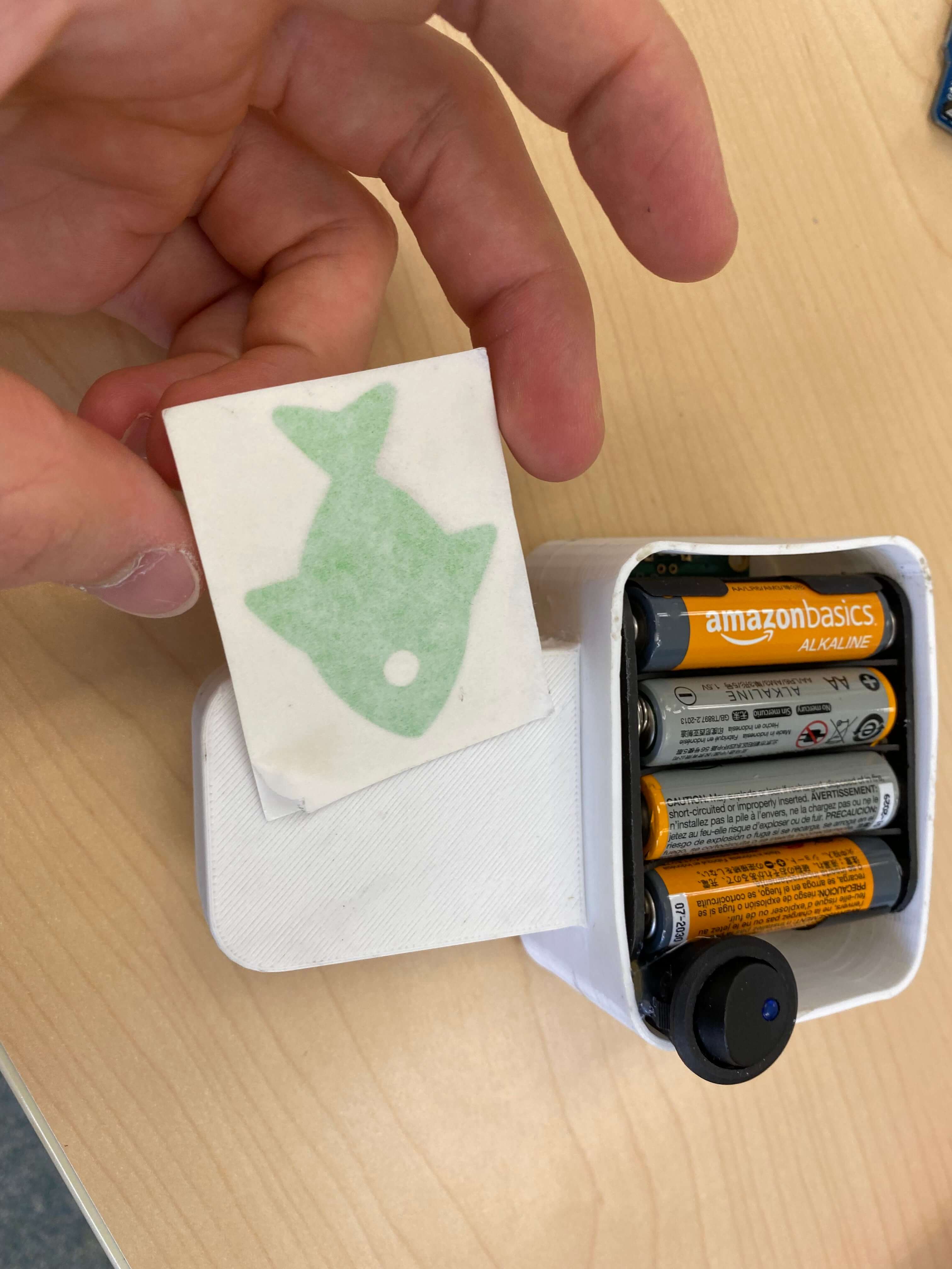
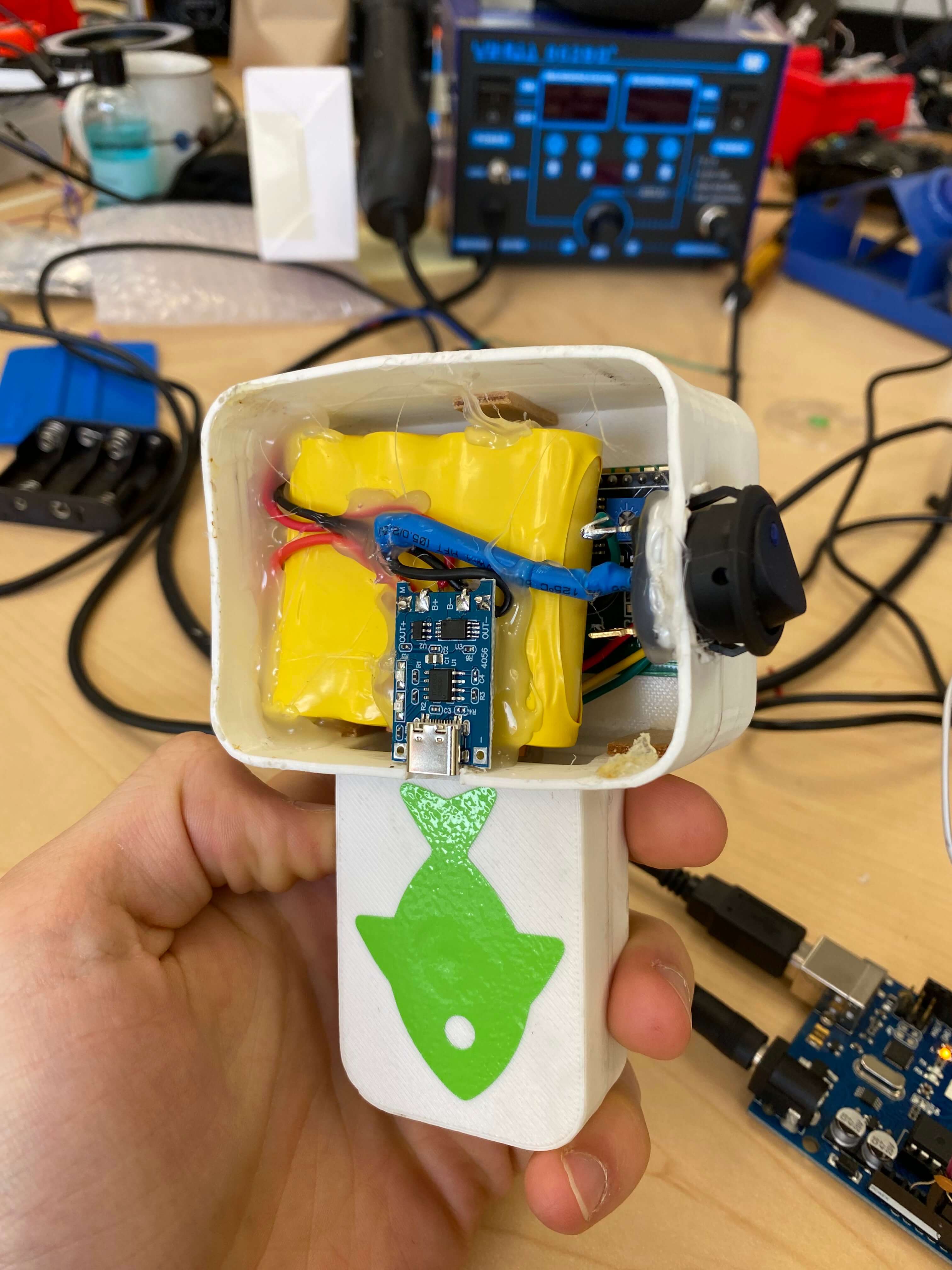
After technically completing my Final Project by pasting a fish Icon on the back of the GameBoy I made Months ago, I have decided that I cannot just leave it like that. Hence, I decided that I will be adding some more stuff. That's why I went online and bought a rechargable 5V Li-ion battery and a 5V USB Type-C Li-ion Battery Charging Module.
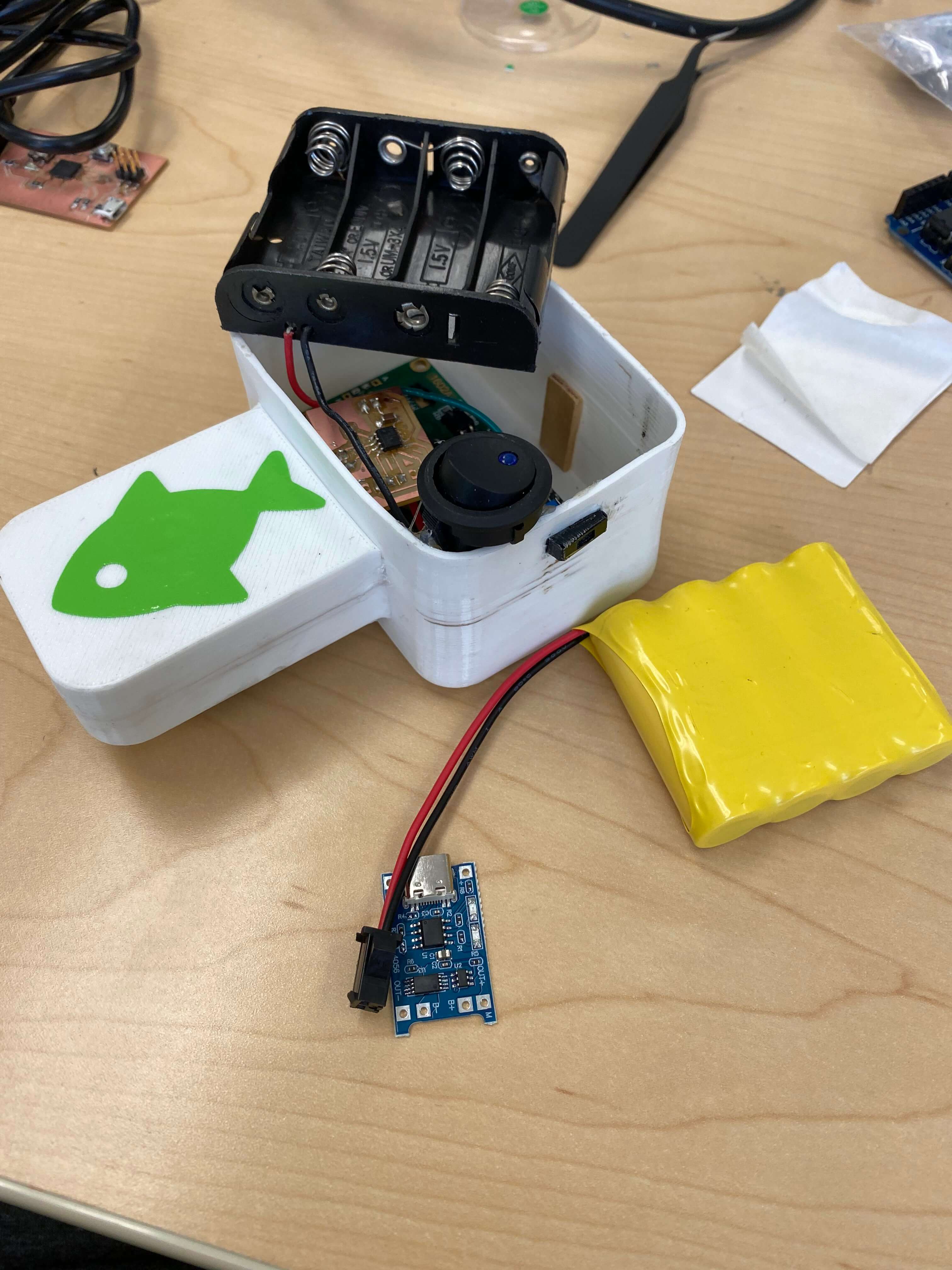
After some work of getting the old parts out, unsoldering stuff, resoldering stuff, doing cable management again, hot gluing stuff, and finally stuffing components inside the GamBoy, I was finally done.
Electronics Part:
For the electronics, I needed to make a board that can take in a 5 volts to power a microcontroller and power/control/read a Joystick and an LCD. As I mentioned in Week 11 - Input Devices, I have initially tested all the devices and the code using an Arduino Uno. Because of the world wide shortage of microcontrollers, I wanted to use the least used microcontroller in our lab to not waste other powerful microcontrollers such as ATtiny1616, ATtiny1614 or ATtiny3216. For this reason I have selected ATtiny402. ATtiny402, while maintaining most of the properties of ATtiny1616, it has less pins (8) and has a way smaller memory capacity. This also forced me to write my code as efficient as possible. I have decided I will be soldering wires directly to the board and wont be using Dupont wires. Hence I decided to have through holes for all the external connections such as the UPDI/POWER, the LCD and the Joystick. Since, I was going minimalistic with my microcontroller I decided that I will go minimalistic with the PCB itself.

The board is 1.5" by 1". Unfortunately, ATtiny402 was not in my KiCAD library, thus, I had to go online and download the symbol library and footprint library for the ATtiny402. To learn how to download different libraries check out my week 7 - Electronics Design Assignment page. After downloading the libraries I simply included it to the sketch and started working on it. To learn more about Electronics design and milling go to week 7 - Electronics Design.
Exterior Design Part:
To learn more about Computer Aided Design go to Week 3 - Computer Aided Design.
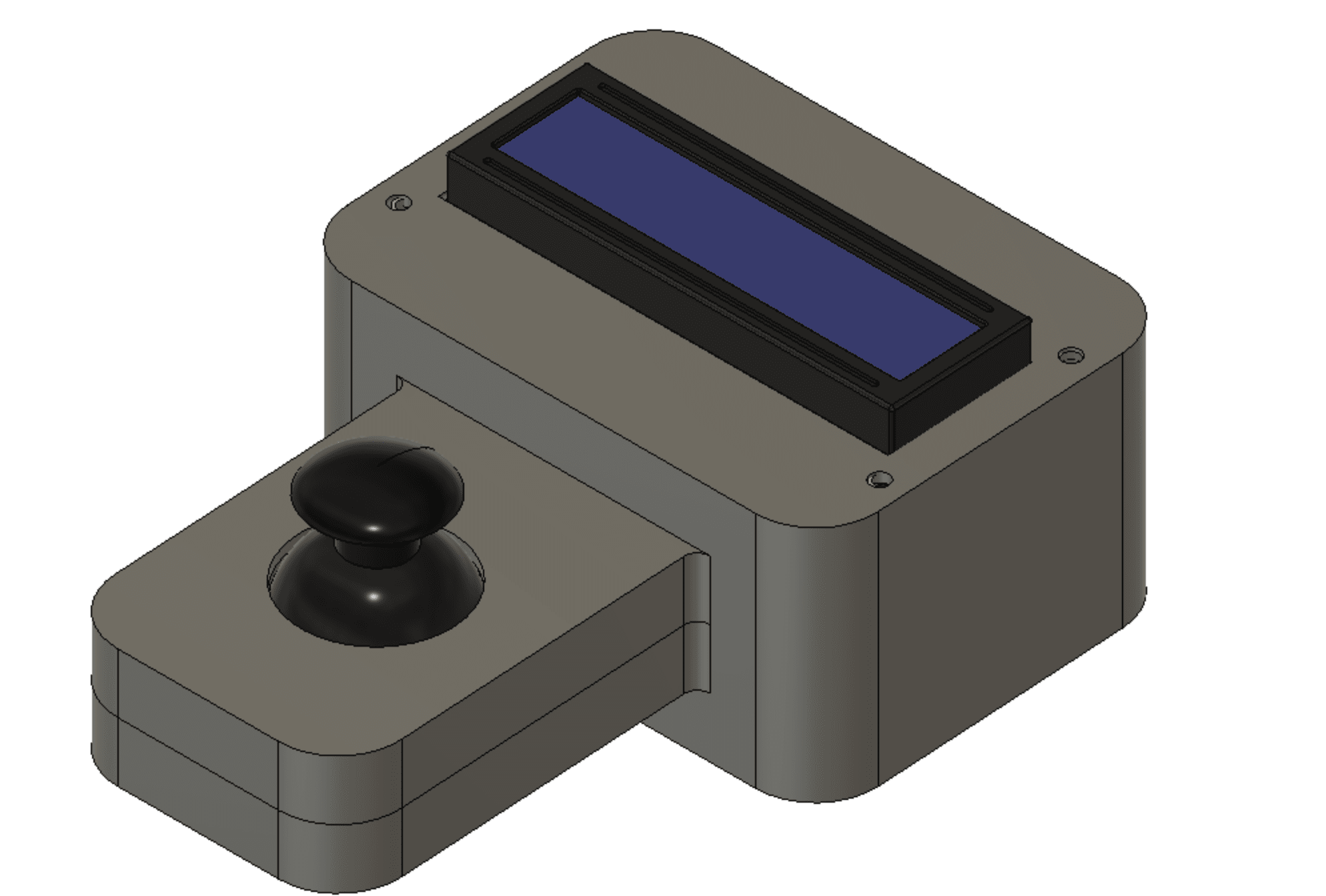
Before starting designing, I first looked at the items I have and imagined a design that will suit my game and the items I have. Hence, I imagined a small box with a handle in the middle. After that I started taking measurements of the items I have sush as the LCD, Joystick, PCB, Battery Pack, ON/OFF Button.
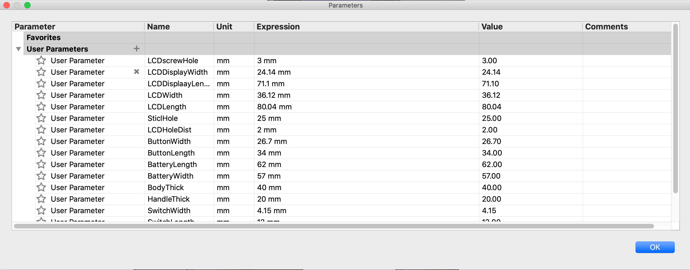
After measuring the items, I have entered all the data to Parameters section in Fusion 360. After having the parameters I started by creating a sketch of all the materials in the first X/Y space.
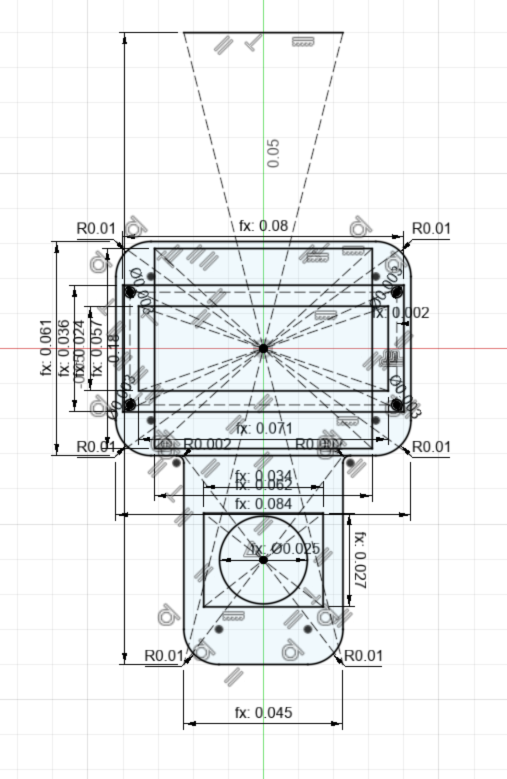
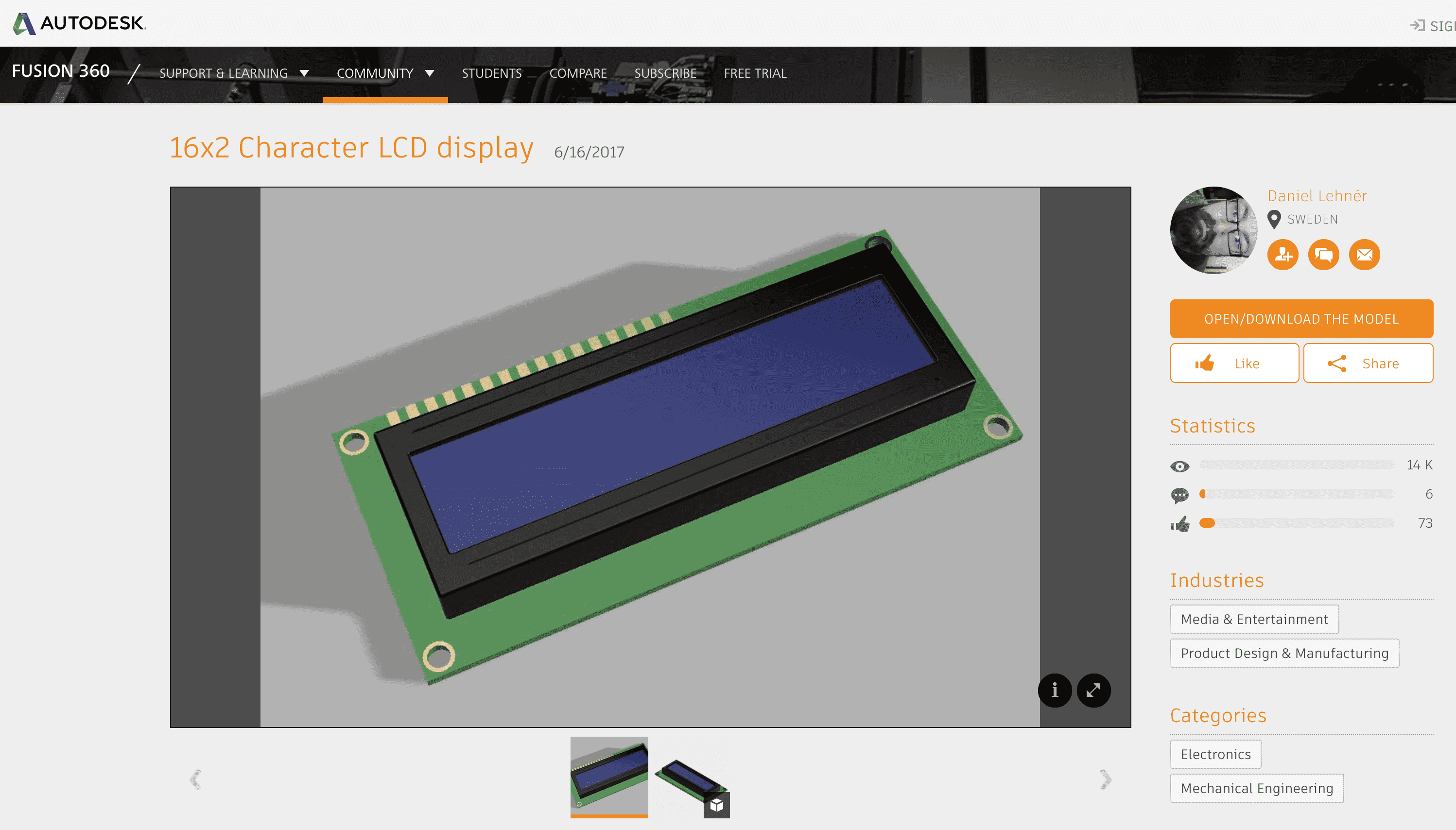
After having the sketch, I extruded the parts that needed using the sketch. Then I have did some more edits by creative new sketchs on top surfaces and using the project tool to copy and paste the sketches I made in the first sketch. I have also imported external designs of the LCD, the Joystick and the Battery Pack. To do this I first went online and search for the design. You can get these open source designs for free at Autodesk Gallery.
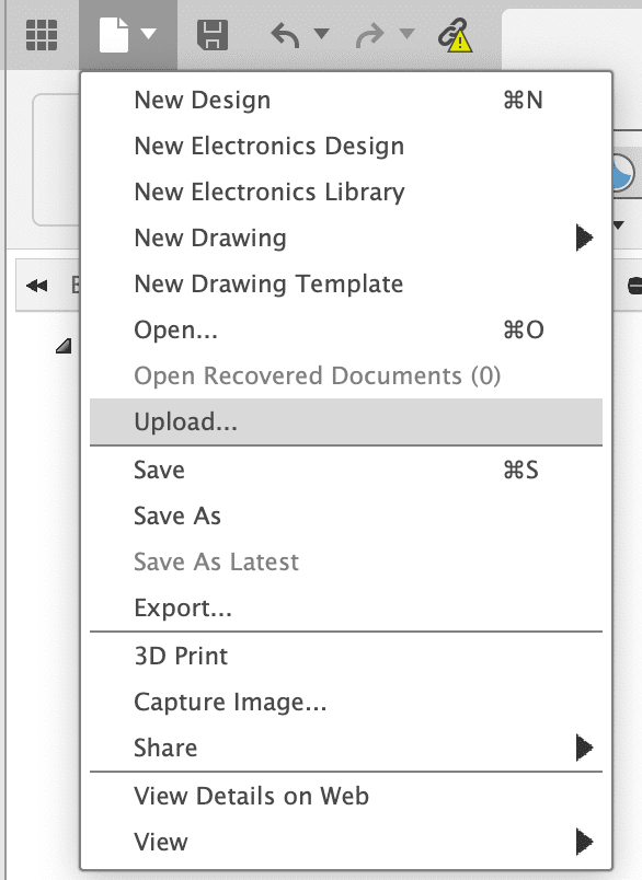
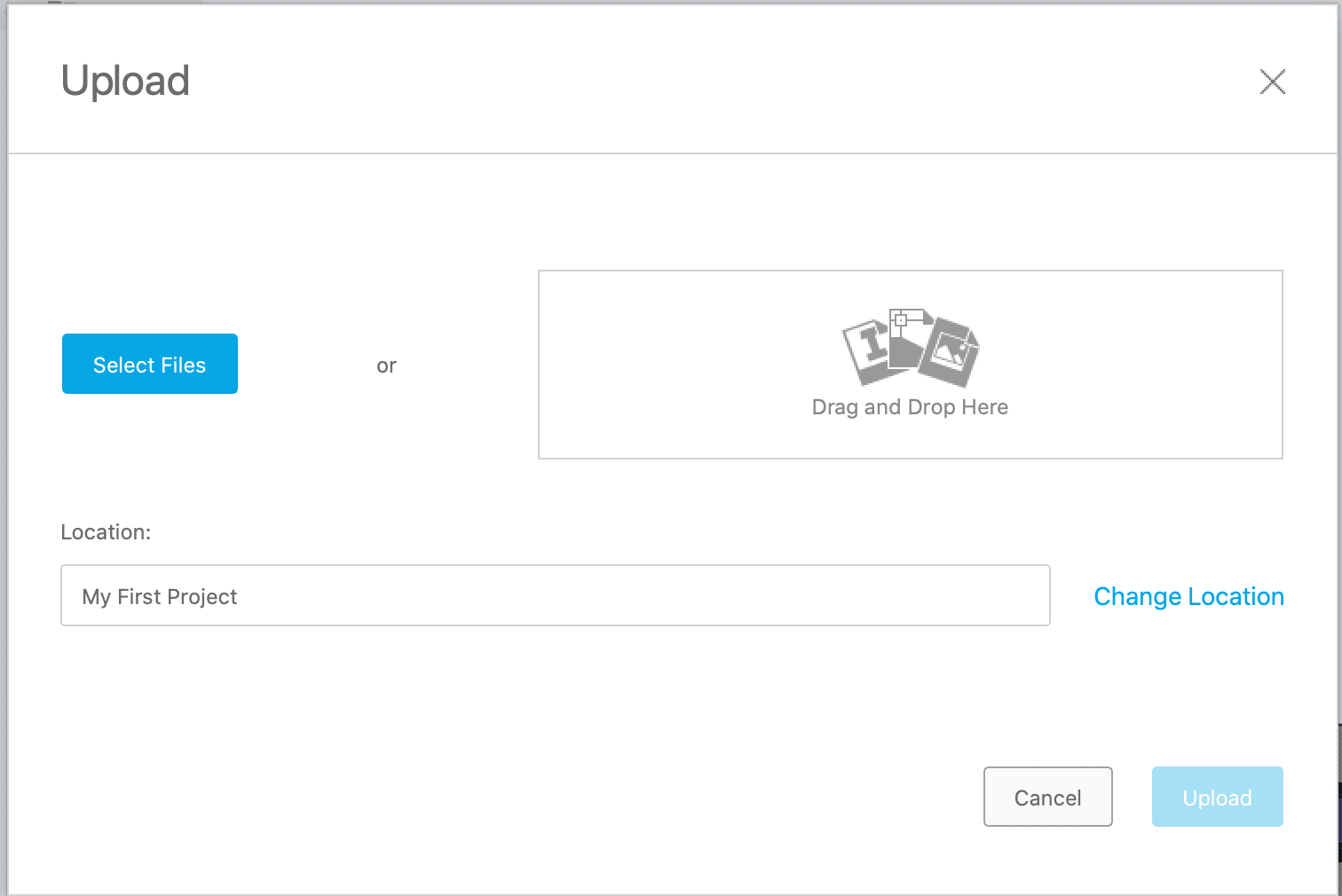
After downloading the Model as a Fusion 360 File, on the top left, from where we save the file, there should be an option called upload click that and select the files you just downloaded. These files will now appear in your fusion designs library.
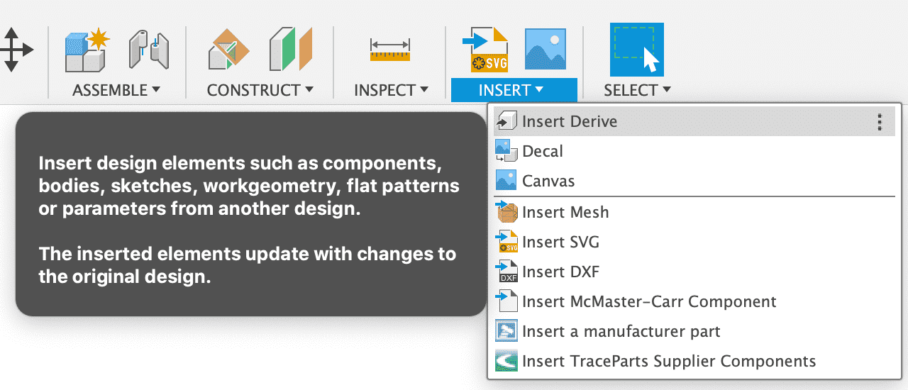
Now, to put them into your current design. While in the DEsign mode go to the "Insert" menu on the top left part of the screen and click to "Insert Derive" and select the design you want. While importing that design you can select which components you want one by one.
At the end it looks like this: