Electronic production
Group Work
Jargon.
Feed Rate
Feed rate is the velocity at which the cutter is fed, that is, advanced against the workpiece. It is expressed in units of distance per revolution for turning and boring (typically inches per revolution [ipr] or millimeters per revolution).
Spindle speed
The spindle speed is the rotational frequency of the spindle of the machine, measured in revolutions per minute (RPM). The preferred speed is determined by working backward from the desired surface speed (sfm or m/min) and incorporating the diameter (of the workpiece or cutter).
Plunge rate
Plunge rate is the speed at which the router bit is driven down into the material when starting a cut and will vary depending on the bit used and the material being processed. Sometimes it is possible to cut at a faster feed rate by increasing the spindle rpm.
Depth of cut
The measurement. (normally in inches or millimeters) of how wide. and deep the tool cuts into the workpiece. Speed, feed and DOC work together to. determine the Metal Removal Rate (MRR).
Tooling
Tooling, also known as machine tooling, is the process of acquiring the manufacturing components and machines needed for production. The common categories of machine tooling include fixtures, jigs, gauges, molds, dies, cutting equipment and patterns.
Group Project
We struggled quite a bit in actually milling this board in truth. In our time working on this we never actually finished milling the piece. Now what problems did we run into? What a wonderful question! For one the first time that we started working on it in mods we accidentally opened the wrong program. We knew that it was a server program under Roland Mill, however we accidentally picked MDX-20 as opposed SRM-20. Now if you were wondering whether or not this would be a big deal turns out yes. What basically ended up happening was it milled out a tiny little square of all of the copper as opposed to an actual shape.
This was admittedly upsetting to us, but even worse we didn’t even have that happen the first time we tried to print it. The first time we tried to print it there was an issue with the Z-axis so instead of milling it just slightly skimmed over the surface. Since this issue occurred we weren’t able to uncover our larger mistake until we actually did the whole process twice.
Twice wasn’t the end of it though. Since at this point in time we still had a little ambition and faith in our own capabilities, so we went back through to actually pick the right server program. This naturally led us in the right direction in regards to size, and actually, ya know cutting something out. Our own incompetence still got in our way though, and we proceeded to mess up the zero point for the Z-axis about three times. One time, we had the axes perfectly set and felt really good. However when we went to cut it just didn’t cut at all, it stayed off of the surface the entire time. We assumed that it may have been a file issue.
In retrospect we now know that the team member who taped the board to the machine did a poor job, and the piece was exceptionally uneven. Nonetheless we went back to mods to try again. This time however the team member who was doing the work in mods made some mistakes, that the rest of us didn’t catch, and forgot to properly zero everything, so when we ran this file the bit shot up about 20mm and started carving away our board out of thin air.
Luckily after going through fixing that issue, and at this point a newly discovered tape issue, we went at it again, and very neatly carved out our board. Yay! The celebration was undercut however as when we went to actually cut it out of the larger piece, we messed up again, and the whole thing didn’t even cut. At That is where we find ourselves now. With our once hopeful eyes now downcast, defeated by a machine. However for as much as it was a discouraging, moral breaking event, I think we’ve learned a lot. At very least we’ve learned plenty of ways to not use the mill and I think that as we go forward we’ll all be better makers for having gone through this. At very least I hope we’ll be able to actually mill a board. after all this we take a break for a few weeks.
after making shure to not repeat any of the mistakes from before we use mods to generate the mill files unfotunitly the bit deosnt cut throw all the copper.
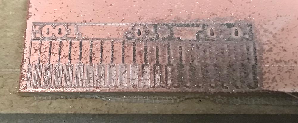
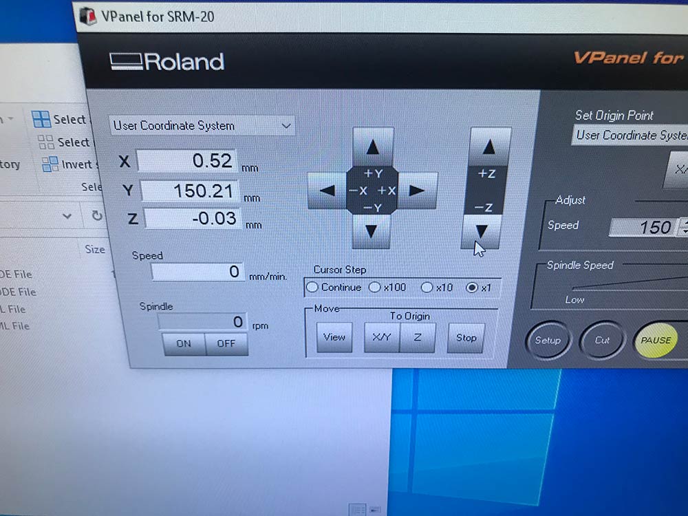
to fix this I moved the bit off the board and set the z below the copper by .03 mm. here is the interface of the desktop mill.
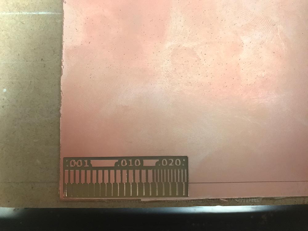
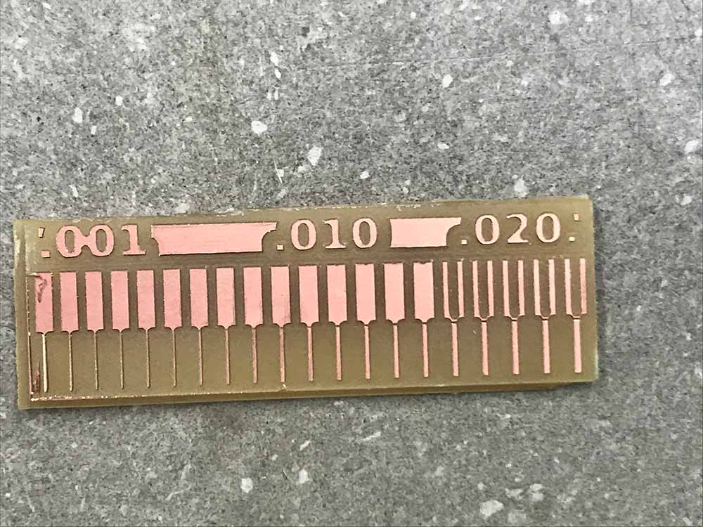
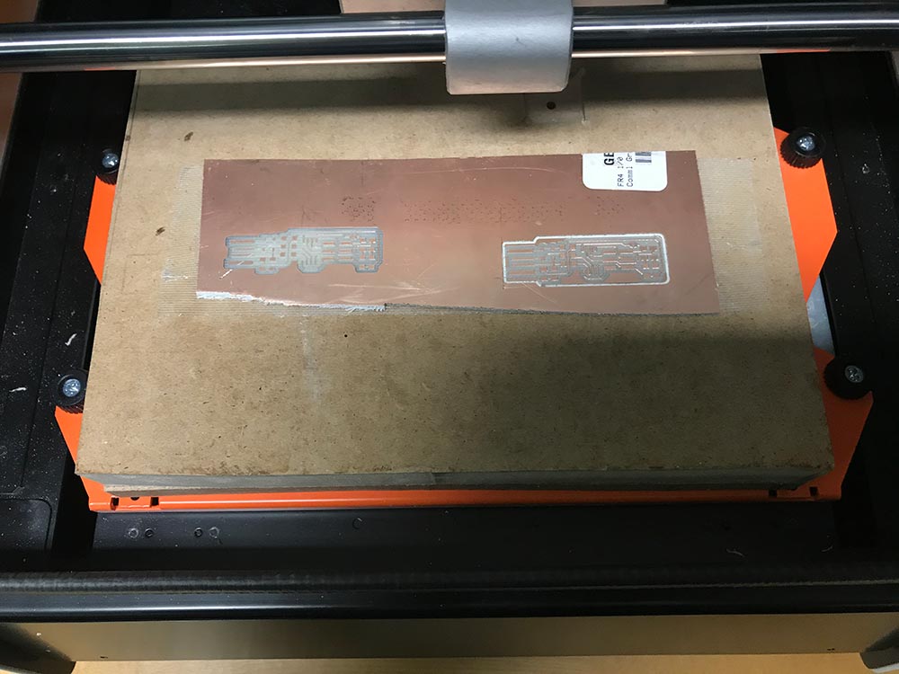
after that the milling had no problems. here is the board pre cut out and after geting cut out of the rest of the board.
Solo Work
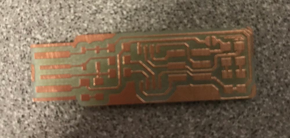
The solo assignment this week was to make the FabTinyISP this is a board that is used to program other boards. To make this bord first you get the plan for the board and then cut it out. I used mods to generate the filles needed by the desktop mill I used Mods. to get the cut files to work in mods you need to select the Png that you want to use after you load it into the top left board. the nezt box lets you selcet the type of cut. then you need to set the origin x, y, and z to zero and also disconect the output of that box from the next box and reconect the box to the server progrm that is save. then hit calculate and it will grenerate the files needed to cut in the ROland. I used a Roland mill to mill my bord. Here is an image of the final product of that. and a cut out board with no components soldered onto it
 |
 |
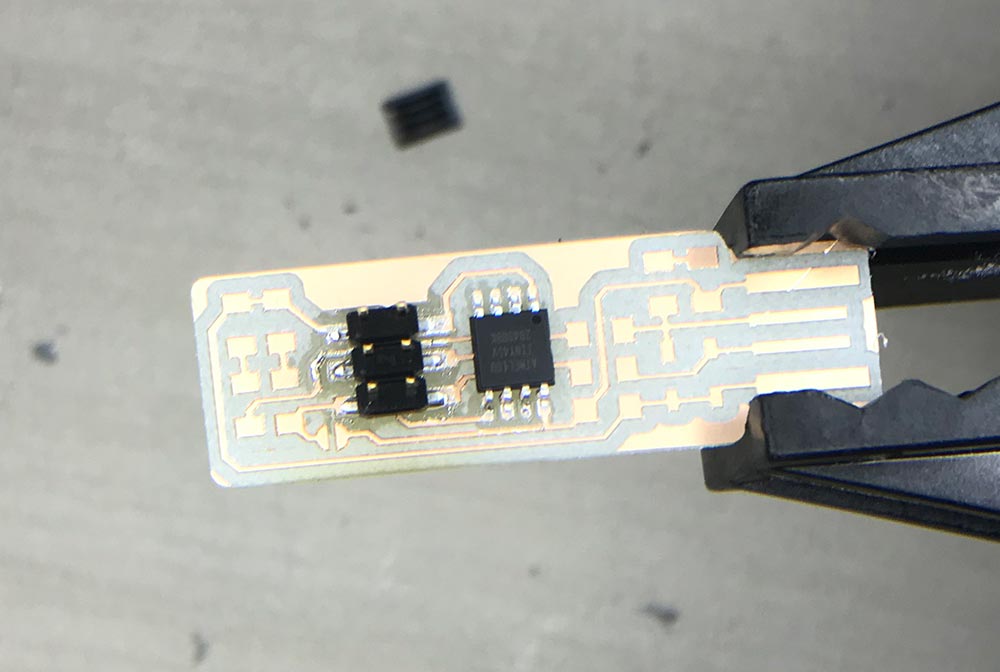
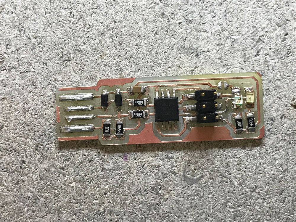
After getting the board the first two components that I soldered on were the computer chip and the connector pins. I then burnt a finger and stopped for the day here is what my board looked like.
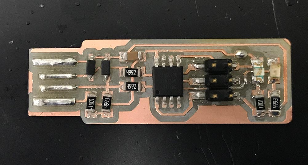
I then soldered on the rest of the components and made a mistake with the direction of the zener diodes and the value of the resistors for two of the components. here that is.
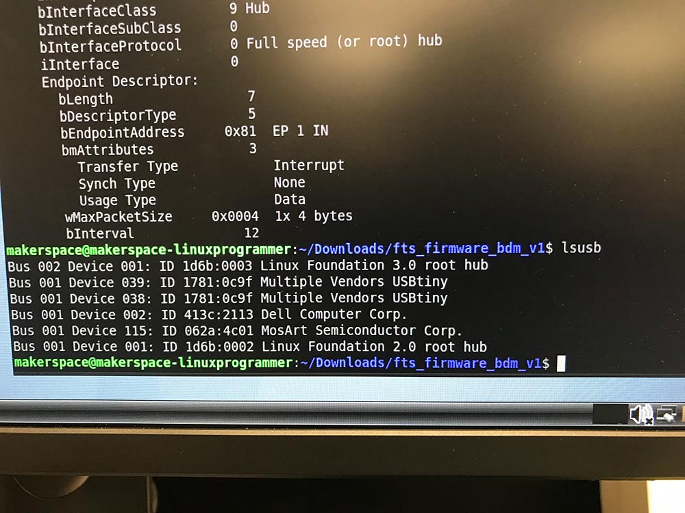
I then went to program the bord only to learn about the mistakes that I had made. While I was waiting I used sandpaper on the usb connectors to make them more uniform in size. I then programmed the board and after all the programing i got this screen showing that the computer was reading my board and the corect peace of hardware
After the programing I then unsorted the jumper and got this as my final board .
here is a link to my files look in week four for this week's files. here is the link