Week 8; Embedded programming
This week is all about learning how to program an embedded microprocessor. I Don't know anything about it so it is again a week full of tutorials and workshops. This week I will first do some online research and after Henks Class (on friday this time) it is time to work on the assignments
Wednesday Global Class
The different microprocessors that we'll use are named, the simple boards that we can build. The C-language is introduced and the workflow and standards of communicating with the boards are listed. It feels more like a summary of all the things used than a lesson.
Weekly Assignment
In my own words
Group assignment:
Compare the workflows and performances of different architectures
Individual assignments:
- Read a microcontroller datasheet
- program your board to do something. Try out different environments and possible languages.
Planning this week
Due to Corona, we have to split up the group in halves to work in the Waag, I am scheduled to be there on friday this week (instruction and group assignment) and on monday and tuesday, I will join in the afternoons. I work on monday-morning, tuesday-morning and friday, so it is quite a tight schedule. I made my planning around this schedule.
| Day | Lesson | subject/activity | activities |
|---|---|---|---|
| Wednesday | global class | make this plan | |
| Thursday | Online research on | microprocessors embedded programming in C | start documenting |
| Friday | 'Local class at Waag | embedded programming | group assignment architecture |
| Saturday | study known unknows | work on assignment | global open time for questions |
| Sunday | work on assignment | family-time | |
| Monday | Work for my job and students | Documentation | |
| Tuesday | Work for my job | local Fab time | Documentation |
| Wednesday | presentations | ready to present | fix last things |
Online research
Its time to dive into that little black box that is called a microcontroller which is on the circuitboards that I already built in the last weeks.
I found a few great explanations on microprocessors that has many pictures and schemes. I really like that, because it makes it easier to learn for me. A PDF called Microprocessors made easy on st.com and a tutorial on analogue versus digital on friendlywire.com
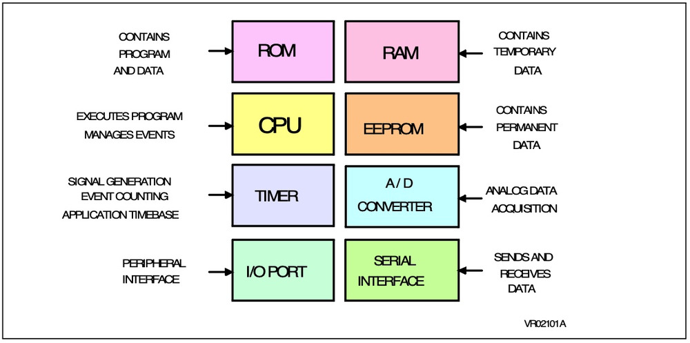
these are the parts in a block diagram of which a microprocessor is build
In another way organised the microprocessor will schematically look like this
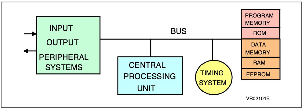 It consists of a way to give input to the controller, that will be processed in the CPU (central processing unit) which is using different types of memory (i.a. for the program, for fixed data, to store input/output data temporally)
It has a timing system that is crucial to do the different steps in the program in the right order and at the right moment.
and then it has ways to give output.
It consists of a way to give input to the controller, that will be processed in the CPU (central processing unit) which is using different types of memory (i.a. for the program, for fixed data, to store input/output data temporally)
It has a timing system that is crucial to do the different steps in the program in the right order and at the right moment.
and then it has ways to give output.
the input and output can be digital or analogue.
- Digital means that there are only 2 possibilities: '0' is equal to 'zero Volt' and '1' is equal to 'five Volt' (or '1' is 3,2 volts for a 3 volts microprocessor)
- analogue is a measurement of the relative voltage on the pin and then is converted to a number between 0 and 255 in which 125 is halfway. so 0 volts is '0' 2,5 volts is '128' and 5 volts is '255' which then can be
http://www.friendlywire.com/tutorials/adc/
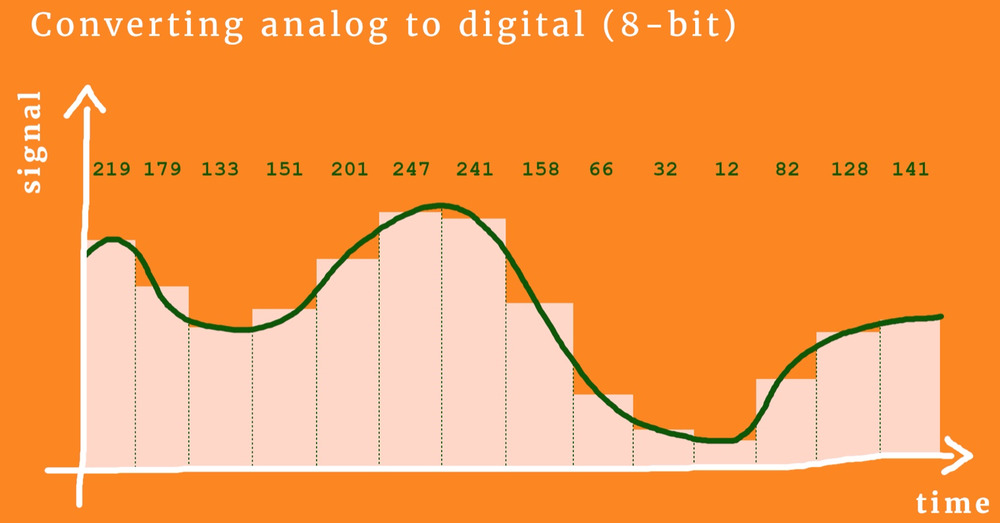
Analogue data can be anything in real life, for example temperature, humidity, sound, light-intensity. So it is great to understand the way that it is converted.
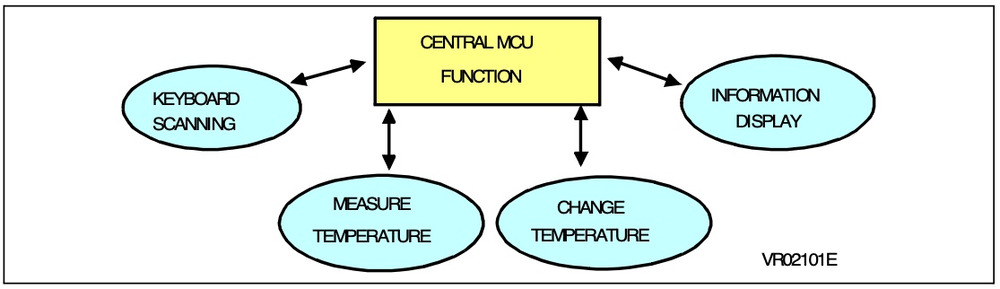
A typical task that a microprocessor can do is convert some input-measurement and input through a keyboard to a certain output in which a machine turns on at a certain level.
Friday Local Class
Group assignment
For the group assignment we looked into the different arduino's and programmed a nice little setup in the arduino-IDE for the arduino-uno in Waag. Arduino code is referred to as 'sketches'.
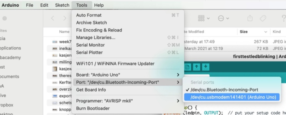
Port
It was quite a search to find the right way to contact the arduinoboard. It is in the 'tools' section of the arduino-IDE and then find the right Port. This is important to remember because it will be needed also with any other board.
first tries blinking
We played around with the very basic setup with the arduino and made different little codes for that. Starting to make it blink. It was really nice to play around with this while Erwin was able to fix all the issues we found, so it all seemed to go quite smooth. We thought of blinking, and made the arduino blink slower and faster.
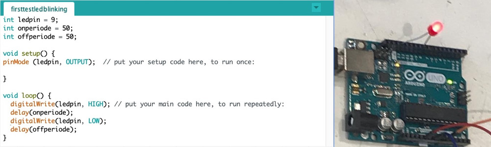 I learned through this that there are variables that you can set:
1int ledpin = 9;
2int onperiod = 50;
3int offperiod = 50;
Int is for a
frequency and human Eye
I learned that the speed of the microprocessor is 1000 actions per second. A movie has 24 pictures per second, so according to that we searched for the right speed of blinking so it would be invisible for the human eye. We tried a frequency with 1000/25 (so it was blinking every 0,04 second.) but the blinking is was still visible. Probably because it was really on half of the time and off half of the time. we changed it to 1000/50 and the blinking was not visible anymore. Erwin taught us the use of the words Dutycycle (when something is 'on') and Downcycle (when somthing is 'off')
1int frequency = 1000/50;
2float dutycycle = 80;
3float downcycle = 100-dutycycle;
With that frequency we did not have to be dependent of the speed of the 'Loop' anymore and the loop can also do other things meanwhile. Playing with the lenght of the Dutycycle we could software-wise Dim the led light (by turning it off for a longer (dimmed) or shorter (brighter) time within the frequency)
Adding a button
I asked Erwin why there is a double negative with the button and the led in the example that Henk gave us. (the led turns high when the button turns low) It seemed complicated to me. Erwin explained that it is easier to recognize a difference between 5Volts and zero than it is to recognize the difference between zero an 5 volt. Which is due to the fact that 5 volts is quite stable and 0Volts is interrupted by all kinds of things in the room. so very often the button will not be at exactly 0Volts and therefore the program won't know how to interpretate that.
With that explanation everything was clear and we used that in our little code.
We tried some 'if' code with a button we called Erwinsbutton
in void:
1pinMode (Erwinsbutton, INPUT_PULLUP);
and in the loop:
1if (digitalRead(Erwinsbutton) ==LOW){
We made some cleanup in the code and at the end we had some nice code with which we could turn the led high and low with the potentio-meter. and it would only burn if the button was pushed.
 1int analoginput = A0;
 2int erwinsbutton = 7;
 3int ledpin = 9;
 4int frequency = 1000/50;
 5float dutycycle = 60;
 6float downcycle = 100-dutycycle;
 7int potentio = 0;
 8
 9void setup() {
10pinMode (ledpin, OUTPUT);  // put your setup code here, to run once:
11pinMode (erwinsbutton, INPUT_PULLUP);
12}
13
14void loop() { // digital loopy
15  if (digitalRead(erwinsbutton) ==LOW){
16  digitalWrite(ledpin, HIGH); // put your main code here, to run repeatedly:
17  delay(frequency*dutycycle/100);
18  digitalWrite(ledpin, LOW);
19  delay(frequency*downcycle/100);
20
21potentio = analogRead (analoginput);
22dutycycle = map (potentio,0,1023,0,100);
23downcycle = 100-dutycycle;
24}
We played around with the different ready-made boards that were laying around. I would like to know more about the makey-makey, since it seems really nice to be able to use some cursor-effects in different tools.
quick test
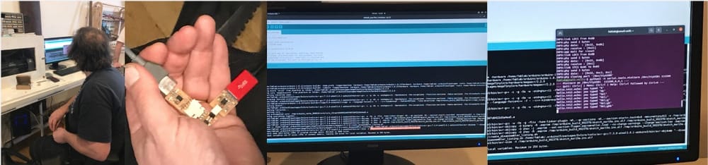
Henk showed us quickly the setup on one of the computers at Waag and used several Terminal windows to talk to the boards in order to send the code. It was a mystery to me how this would work.
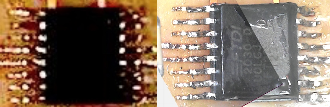
After a very quick test of Henk if the boards were working, (my HelloElvis is working, My FTDI is working but my UPDI is not working).
UPDI
The UPDI-board is connected to the USB on the computer, I can see the FTPI popping up in the system report but it does not connect to the hello-board and all these mistakes keep popping up if I try to upload something On friday Henk looked at the UPDI and conluded that it is probably one of the threads under the FTDI-processor. I tried and measured all of the connections but could not find anything. We could not fix it late fridayafternoon and he lent me one of his UPDI's. So I could work in the weekend.
setup for connecting the ATtiny
Erwin did a quick explanation of how we should set it up, and that if we use the Arduino-IDE we could either install Py-UPDI or find the right downloads so the ATtiny can be connected to Arduino-IDE. Quentin said something about that on wednesday.
Individual assignments
- Read through a Data-sheet of a microprocessor.
- Design and upload a program onto your Hello board
Tha data-sheet
Luckily I already looked up some bits and pieces about the microprocessors, and in week 4 I looked at the datasheet on the SAMD and in week 6 on the ATtiny. Therefore this task will be easier this week. I already know a few parts that I'll need to find in the datasheet. in my case a ATtiny412.
So I want to learn something about the ATtiny family:
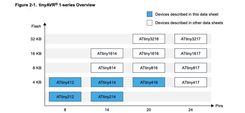
about how the AtTiny is build up and what are the different peripherals
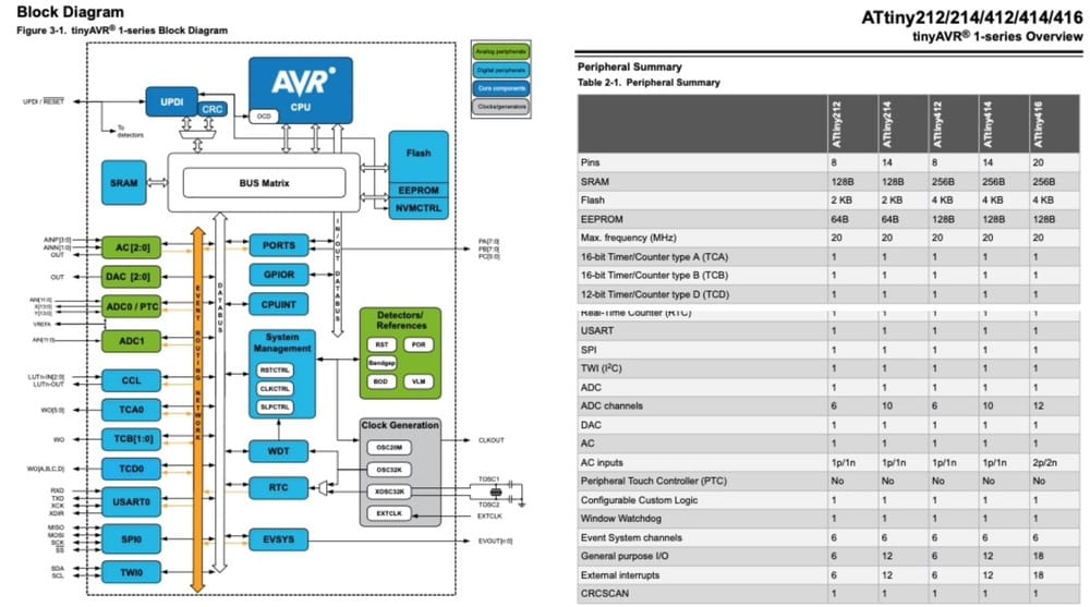 the memory and ho
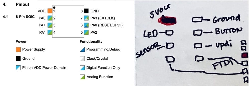
and of course the most important part for now is the different functions of the pins of the Attiny412. With the information of 2 weeks ago I made a little drawing of my Attiny and how it is connected to my parts.
the memory and ho
and of course the most important part for now is the different functions of the pins of the Attiny412. With the information of 2 weeks ago I made a little drawing of my Attiny and how it is connected to my parts.
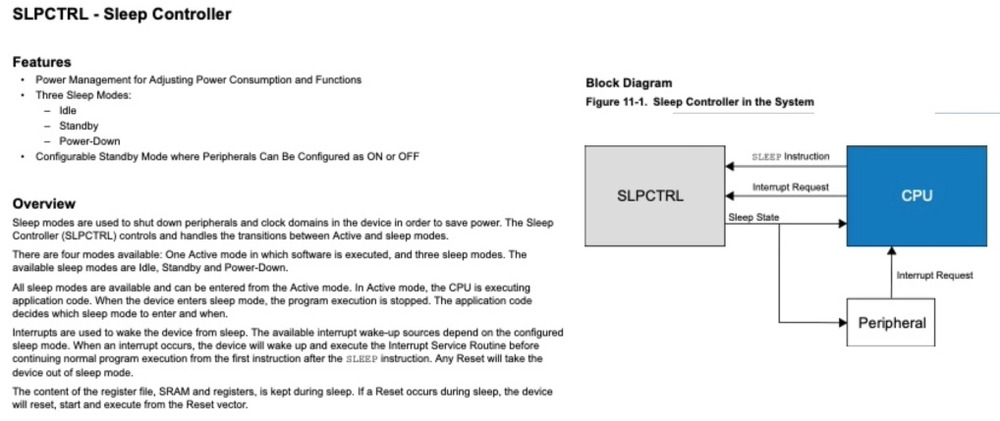
I am very interested in not using energy all the time for my final project so I read into the sleep-controller, but that is a bit too much to use this week. I will spiral onto that.
writing in C-language
C is completely new to me, in the arduino IDE you are using a lot of C, I don't quite know what is what. After seeing some things it reminds me of the only coding-experience I have, which was in Basic, way back in the 80's. Time to look for some information on the basic setup of an arduino-sketch and I found 2 PDF's that gave me a nice overview.
Things I used so far
global variables:
Before the setup it is already possible to set some global variables
- 'Int' is a variable that is not changing in value
- 'Float' is a variable that will change in value due to something in the loop
Setup
It will run only once and defines the initial state of
pinModefor setting the Pin functionality- state of pins (for example:
pinMode (ledpin, OUTPUT);) - state of variables (for example
Serial.begin(9600);)
Loop
Here is the program that will run continuously and where the real magic happens. First there is Input in the loop, then its time to do something with the data and at the end the output comes.
void Loop()means that the loop is emptied when it starts over again. So if you want to keep a value longer than one loop, then you have to make a 'Float'if (this has value something){that}means if 'this' is true then 'that' has to happenif (this has value something){that} else{such}means if 'this' is true then 'that' has to happen of it is not true than 'such' has to happen.digitalRead (pin)means read the value of a digital pin (LOW or HIGH)and convert to 0 or 1.analogRead (pin)means read the value of a analogue pin, somewhere between 0 and 1023. (10bit)digitalWrite (pin, value)means send the value to a digital pin, (LOW or HIGH) or 0 or 1.AnalogWrite (pin, value)means send the value to an analog pin, the value can be something between 0 and 255 (8bit)map(pin, value-in-low,value-in-high,value-out-low,value-out-high)is used to convert the analogRead to something different than 0-1023, for example 0-255 (analoguewrite) or 0-100 (percentage)
Saturday
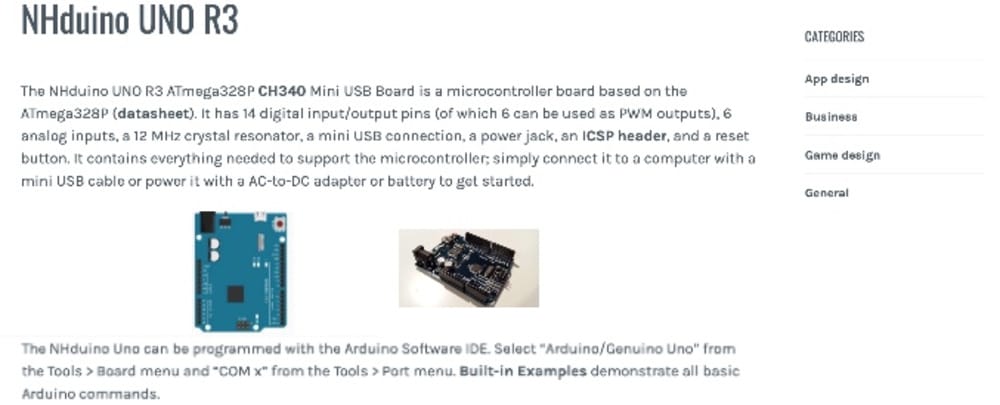
On saturday I started out by connecting my own clone-Arduino that I had laying around from a project that never worked out. Luckily I did get a set of electronic bits and pieces with that and a breadboard. I don't remember how I connected it earlier. But by typing the name and Make in google I found the right settings to use with Arduino-IDE and was able to make the same boards as we did on friday.
Now I connected everything (My USB-C USB-converter connected to both the FTPI an UPDI) on saturdayafternoon and had no idea.
- I could not find anything in the lecture of wednesday, about how to change to the right settings in de arduino-IDE.
- in the mattermost-channel I only read about things that were not okay:
- compiling (I don't understand if that is translating or putting on the board) Bootloader could be the other thing.
- something with the Led being on a digital pin instead of an analogue pin (but we build a solution for that, yesterday)
- something with the Rx and Tx being switched
- something with USB-connectors to connect both FTPI and UPDI to a mac.
I did not have any idea were to start finding the right setup for too many variables.
Saturday open time
Luckily for me open time started an hour earlier (summertime coming up) and I only realized that just before it started. Because of that I did not have to wait extra long before I could find some extra help on starting this whole thing.
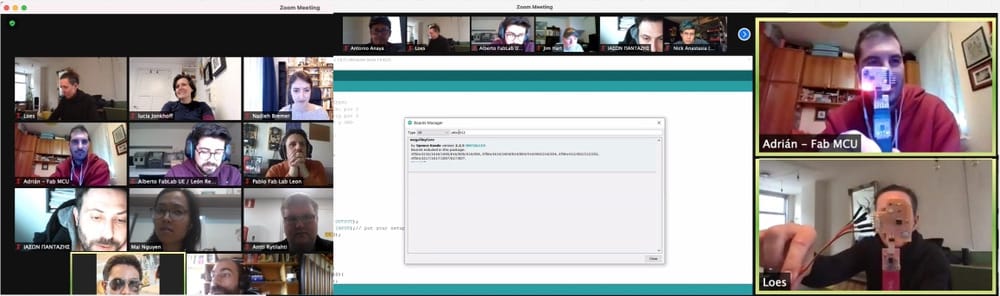 Adrian was very patient with me and explained the setup that he did for Arduino-IDE and had very well documented on his Adianino-site.. For that I had to download the [megaTinyCore]
(https://github.com/SpenceKonde/megaTinyCore)
on Github and with the steps on Adrians site I should be able to connect my Attiny412 directly to the arduino-IDE and be able to program it.
Adrian was very patient with me and explained the setup that he did for Arduino-IDE and had very well documented on his Adianino-site.. For that I had to download the [megaTinyCore]
(https://github.com/SpenceKonde/megaTinyCore)
on Github and with the steps on Adrians site I should be able to connect my Attiny412 directly to the arduino-IDE and be able to program it.
Another thing he explained is that it is much easier to feed the hello-board from a FTDI plugged into a USB-socket-loader so you won't get confused over the right port and the communication is not interrupted.
A third thing he showed is that it is also possible (when milling and soldering new boards) to have an UPDI with a 3rd pin for power, so you won't need the extra FTDI connection. That is really a good Idea and since My UPDI is broken anyway I will try and make the 3-pin UPDI.
Sunday
Thanks to opentime and the explanation of Adrian I had a good idea of how to connect everything and although finding all the right settings was quite a struggle it worked.
Firststeps are to connect to the right board-manager-url and download the megatiny-core by spence Konde
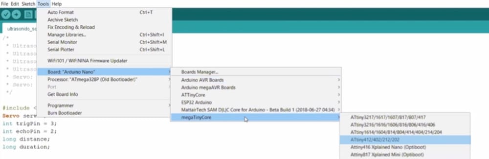
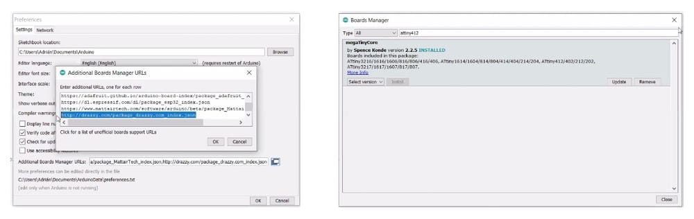 Then install the Megatinycore and select the Attiny412
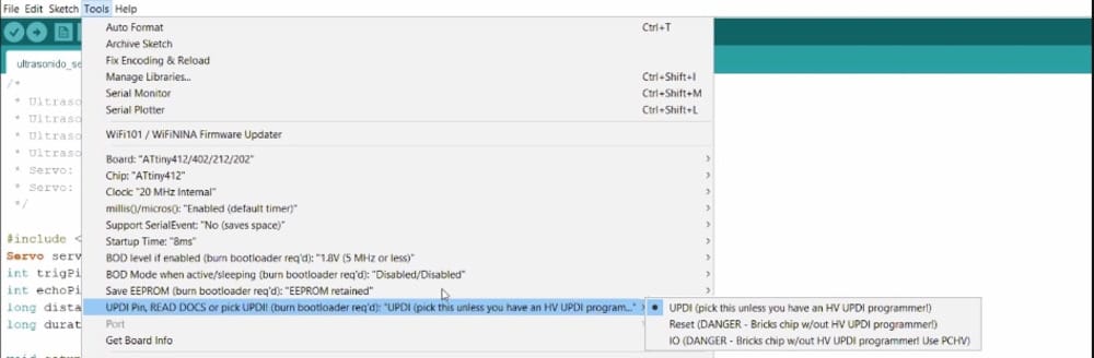
 select the UPDI-settings from the UPDI-pin
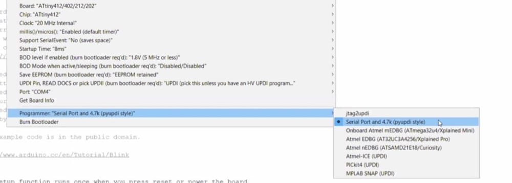
 select the Serial port and the py-UPDI settings from the 'tools/programmer'-menu
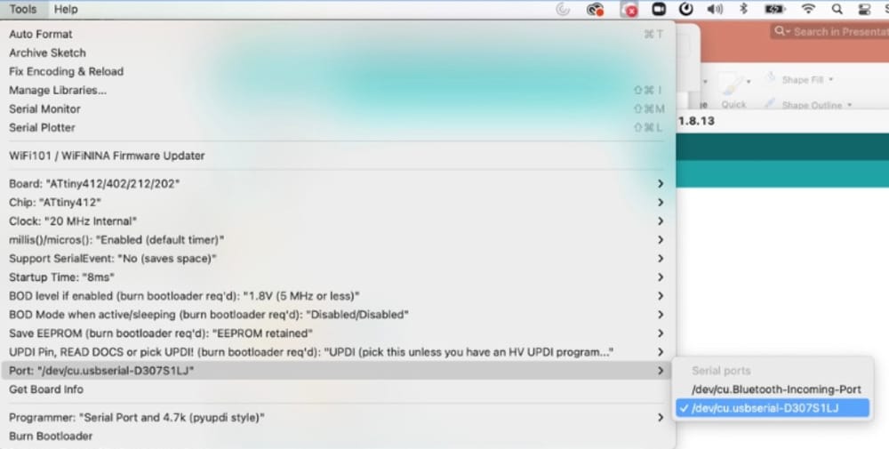
 and then select the right USBserialport from the 'tools/port'-menu
I followed all the steps on Adrians page and now I am ready for a first try.
Code and Upload
With all that done I first tried Neils blinking program. From the datasheet of the AtTiny412 and my notes on the pins on my elvis-board. I found that the Led is connected to pin A6 (or also called 2), I thought that was quite confusing, but since we used the A-numbers on friday with the arduino I thought I try that.
This is the code:
 1#define LED A6
 2
 3void setup() {
 4   pinMode(LED,OUTPUT);
 5   }
 6
 7void loop() {
 8   digitalWrite(LED,HIGH);
 9   delay(100);
10   digitalWrite(LED,LOW);
11   delay(100);
12   }
13
14// hello.t412.blink.3.ino
15// tiny412 blink hello-world, 3-pin UPDI+VCC header
16// Neil Gershenfeld 1/10/21
17//
18// This work may be reproduced, modified, distributed,
19// performed, and displayed for any purpose, but must
20// acknowledge this project. Copyright is retained and
21// must be preserved. The work is provided as is; no
22// warranty is provided, and users accept all liability.
23//
Success
And Yes, we have contact:
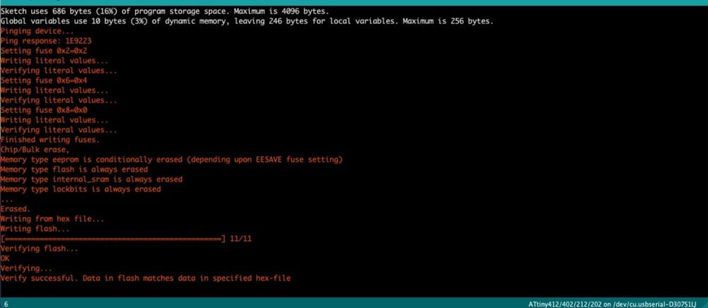
Okay, that is great! first spiral is done. Now I want to upload the same code as for the Arduino. With the changed pins, But that did not work... yet.
 1int analoginput = A7;
 2int button = A3;
 3int ledpin = A6;
 4int frequency = 1000/50;
 5float dutycycle = 60;
 6float downcycle = 100-dutycycle;
 7int potentio = 0;
 8
 9void setup() {
10pinMode (ledpin, OUTPUT);
11pinMode (erwinsbutton, INPUT_PULLUP);
12}
13
14void loop() { // digital loopy
15  if (digitalRead(button) ==LOW){
16  digitalWrite(ledpin, HIGH);
17  delay(frequency*dutycycle/100);
18  digitalWrite(ledpin, LOW);
19  delay(frequency*downcycle/100);
20
21potentio = analogRead (analoginput);
22dutycycle = map (potentio,0,1023,0,100);
23downcycle = 100-dutycycle;
24}
If it is not working I have too many variables to fix this in this code, so I'll first look into the button. for this I changed the code an hid the part about the frequency
 1// int analoginput = A7;
 2int button = A3;
 3int ledpin = A6;
 4// int frequency = 1000/50;
 5// float dutycycle = 60;
 6// float downcycle = 100-dutycycle;
 7// int potentio = 0;
 8
 9void setup() {
10pinMode (ledpin, OUTPUT);
11pinMode (button, INPUT_PULLUP);
12}
13
14void loop() { // digital loopy
15  if (digitalRead(button) ==LOW){
16  digitalWrite(ledpin, HIGH);
17  //  delay(frequency*dutycycle/100);
18  // digitalWrite(ledpin, LOW);
19  // delay(frequency*downcycle/100);
20
21// potentio = analogRead (analoginput);
22// dutycycle = map (potentio,0,1023,0,100);
23// downcycle = 100-dutycycle;
24  }
25else { digitalWrite(ledpin, LOW);
26  }
27}
It works:
To make the sensor work, I made a shorter code for the sensor to operate the light and find out how that works:
 1int ledpin = A6;
 2int sensorpin = A7;
 3int sensorvalue = 0;
 4
 5void setup() {
 6  // put your setup code here, to run once:
 7 pinMode(ledpin, OUTPUT);
 8 pinMode(sensorpin, INPUT);
 9}
10
11void loop() {
12  // put your main code here, to run repeatedly:
13sensorvalue = analogRead(sensorpin);
14
15if(sensorvalue > 512) {
16    digitalWrite(ledpin, HIGH);
17  }
18else {
19    digitalWrite(ledpin, LOW);
20  }
21}
The sensor is not working it seems, but I cannot find a way how it does work...
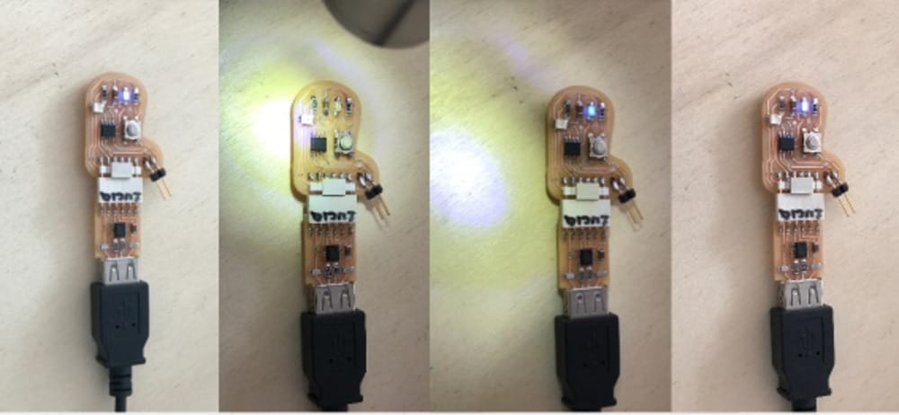
I looked in our electronics-set that we have at home to test what a phototransistor really does.
![]() Here I found that the LED would be brighter if the surronounding light was lower. (I tried to make a good set of photo's but it is hard to see the difference)
Here I found that the LED would be brighter if the surronounding light was lower. (I tried to make a good set of photo's but it is hard to see the difference)
I highered and lowered the switch-point of the sensor, I still cannot figure out really how the switch works but if I shine with a flashlight on the sensor from closeby I can turn it off and on. So with really bright light it would work. But that seems weird, since I would like it to be sensitive to shimmering light.
By tuning the Sensorswitch to 1000 (in stead of 512) I made a led that will turn on and off by magic.
Now I wanted to add the dimmer-function that we build on friday. so I uploaded almost the full code:
 1int photoinput = A7;
 2int button = A3;
 3int ledpin = A6;
 4int frequency = 1000/50;
 5float dutycycle = 80;
 6float downcycle = 100-dutycycle;
 7int potentio = 0;
 8
 9void setup() {
10pinMode (ledpin, OUTPUT);
11pinMode (button, INPUT_PULLUP);
12pinMode (photoinput, INPUT);
13}
14
15void loop() { // digital loopy
16  // if (digitalRead(button) ==LOW){
17  digitalWrite(ledpin, HIGH);
18  delay(frequency*dutycycle/100);
19  digitalWrite(ledpin, LOW);
20  delay(frequency*downcycle/100);
21
22potentio = analogRead (photoinput);
23dutycycle = map (potentio,0,1023,0,100);
24downcycle = 100-dutycycle;
25}
26}
And I could see the light fading when I put the flashlight over it.
But it is not confincing, since it will not measure the not so bright lights and the LED is very quickly in its brightest state....
I think I still have to understand more of this phototransistor and how it works, but that is a spiral that I won't have time for this week.
The latest verion of my complete setup:
 1int photoinput = A7;
 2int button = A3;
 3int ledpin = A6;
 4int frequency = 1000/50;
 5float dutycycle = 80;
 6float downcycle = 100-dutycycle;
 7int potentio = 0;
 8
 9void setup() {
10pinMode (ledpin, OUTPUT);
11pinMode (button, INPUT_PULLUP);
12pinMode (photoinput, INPUT);
13}
14
15void loop() { // digital loopy
16  if (digitalRead(button) ==LOW){
17  digitalWrite(ledpin, HIGH);
18  delay(frequency*dutycycle/100);
19  digitalWrite(ledpin, LOW);
20  delay(frequency*downcycle/100);
21
22potentio = analogRead (photoinput);
23dutycycle = map (potentio,0,1023,0,100);
24downcycle = 100-dutycycle;
25  }
26}
Tuesday in Waag
UPDI milling and soldering
My goal was to become independent and have my own working UPDI (in stead of Henks borrewed and wellfunctioning version)
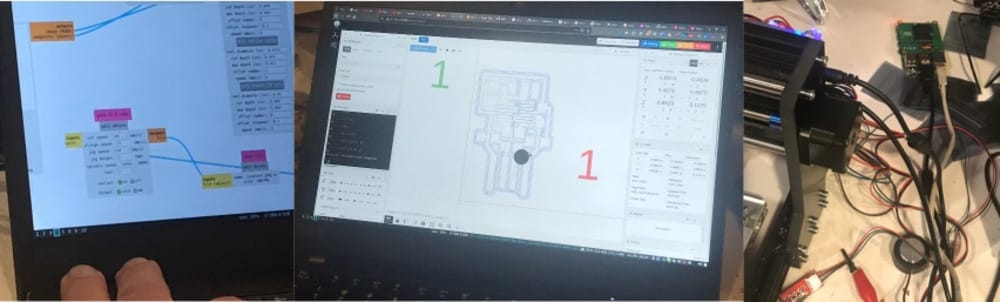
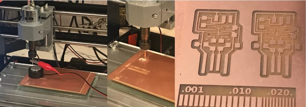
The cool thing was that Henk was finishing his improved 3018-miller and was ready for a millingjob, so my UPDI is the very first board which is milled with the Waag-3018.
He used Mods with a speedbug and a program to connect to the 3018 making the G-code.
 It came out pretty well although the small traces are a bit wobbly. That gives me good hope that I can do this at home from now on.
the result
Having a light softwarewise dimmed with input of a analog sensor.
Magically turn the light on and off without touching the button, I really impressed my kids with that.
Learnings this week
Coding and uploading a code to an embedded chip is all new to me, so a lot of learnings.
- I notice that I am really at a loss when there is too many variables and I don't know how to start (setting up the connections)
- I like the coding within arduino and a bit of C, it seems that it is not very complex and looks a bit like Basic
- It is not the most fun week, but I can admit that getting something working on the board that I made myself is cool. I think it will be even cooler now that I understand the basics about the set-up and can use my energy on thinking out the program and the input and output-possibilities.
- I am happy that making the UPDI with the 3018-miller was a succes, although I don't have a raspberry-py at home I think henks documentation will help me setting mine up ass well.
- There is a lot more to learn, on sesitivity of sensors, on sleeping controller and I just barely touched the coding. So actually it feels that I am not at all able, but very unable. Lucky for me I was unaware of that up until last week...
Links to Design-files
No designfiles this week, all the code is already on the site.