Input Devices
Exploring electronic sensors
Intro.
Welcome! to input device week. This week I have to explore some electronic input devices like temperature sensor, image sensor etc which are available or creating my own if needed.
Week Task:
individual assignment:
measure something: add a sensor to a microcontroller board that you have designed and read it
group assignment:
probe an input device’s analog levels and digital signals
Group assignment: summary
So here we used DSO (Digital Storage Oscilloscope) to look signal generate by input devices such like temperature sensor PT1000 and BH1750 light intensity sensor.
to know more...
Pt refers to that the sensor is made from Platinum (Pt). 1000 refers to that at 0°C sensor has a resistance of 1000 ohms (Ω). It give analog output do one wire comminucation where BH1750 is a digital ambient light sensor it give out digital signal communicate using I2C protocol.
Individual assignment:
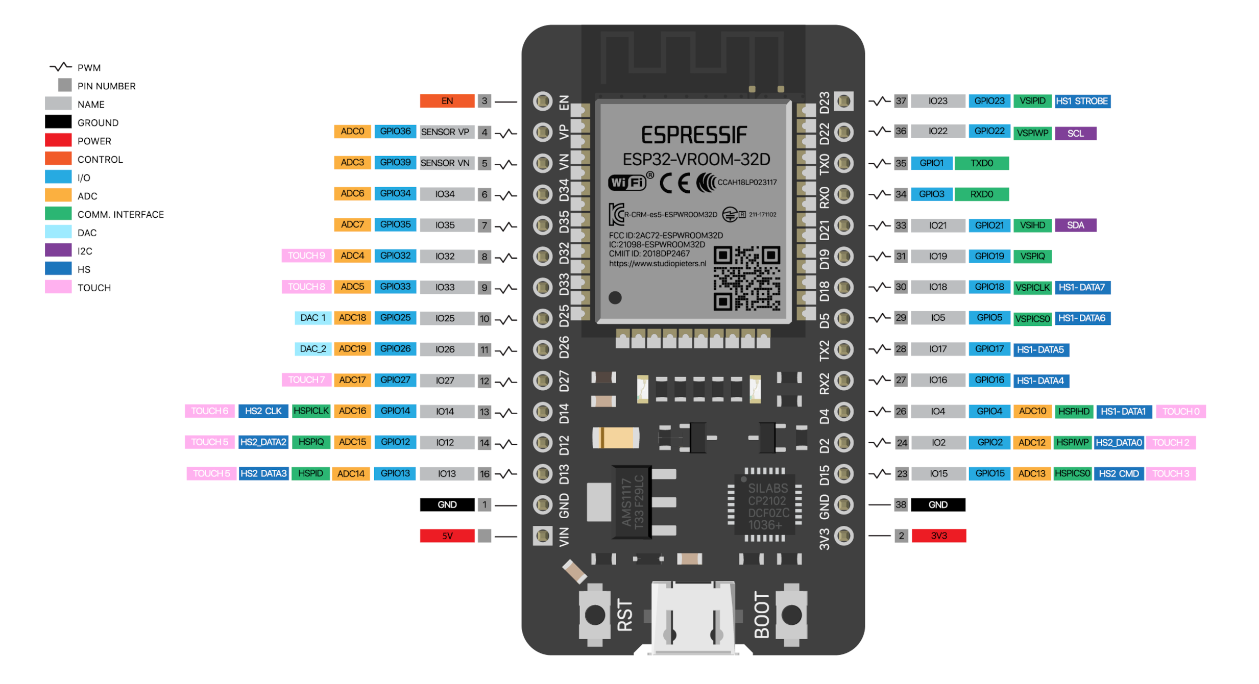
ESP32
ESP32 is a 32-bit microcontroller with inbuilt Wifi, bluetooth and many other features. You can get a ready Development boards. It is low in cost compare to arduino’s boards and highly featured. There is a boards available with camera module useful for application involve image processing. I going to use both board and will also design my own ESP32 board for learning and for integrating it in my Final project.
ESP32 DEVKITV1
I will begin my electronic sensors testing and exploration with this esp32 module until my own designed esp32 get ready to use.
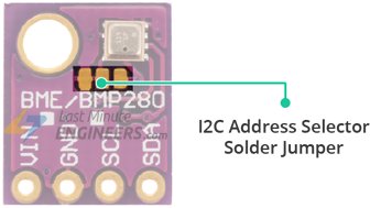
BME280 + ESP32
.jpg)
.jpg)
Humidity sensor measuring relative humidity, barometric pressure and ambient temperature
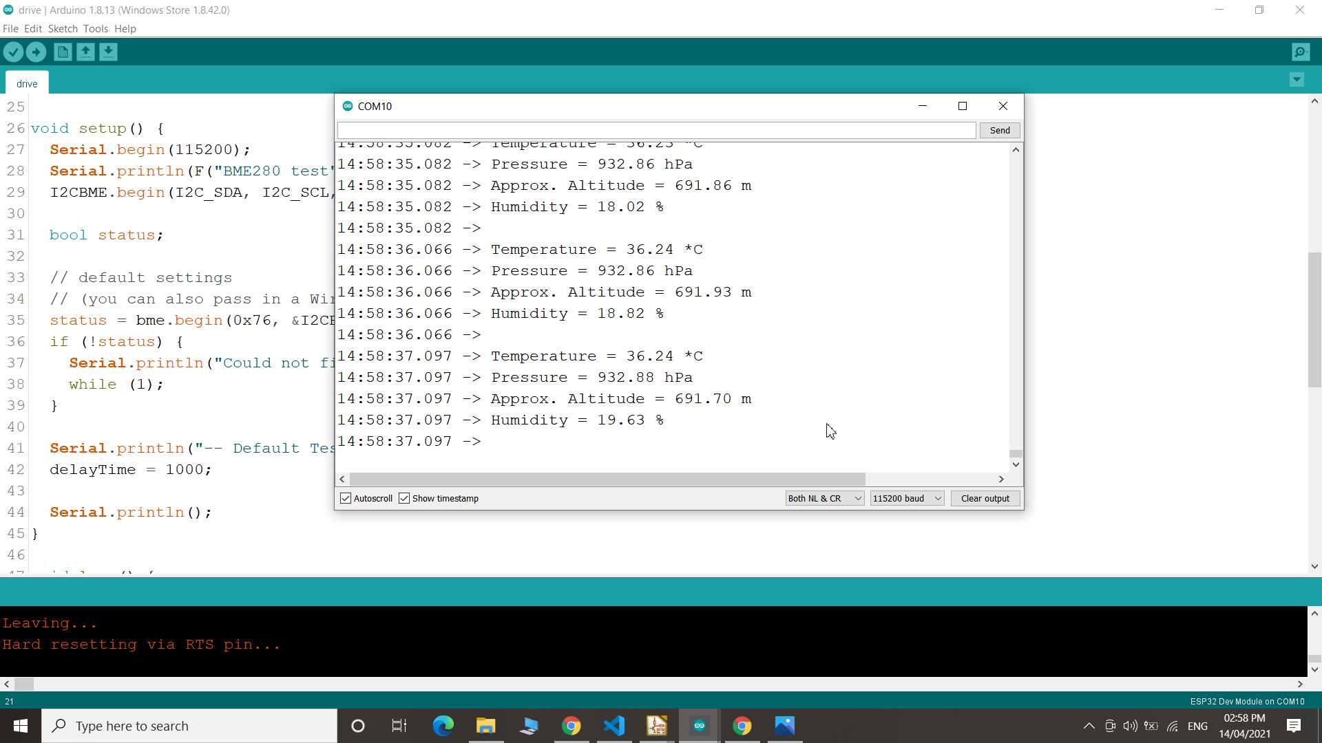
So I refer online tutorial and test run the given example
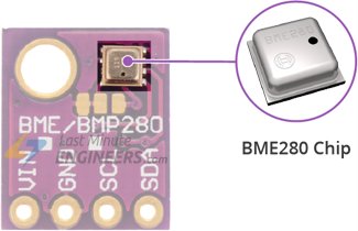
The BME280 is a humidity sensor especially developed for mobile applications and wearables where size and low power consumption are key design parameters. The unit combines high linearity and high accuracy sensors and is perfectly feasible for low current consumption, long-term stability and high EMC robustness. to know more...
*Test Code
#include <Wire.h>
#include <Adafruit_Sensor.h>
#include <Adafruit_BME280.h>

#define I2C_SDA 33
#define I2C_SCL 32

#define SEALEVELPRESSURE_HPA (1013.25)

TwoWire I2CBME = TwoWire(0);
Adafruit_BME280 bme;

unsigned long delayTime;

void setup() {
Serial.begin(115200);
Serial.println(F(“BME280 test”));
I2CBME.begin(I2C_SDA, I2C_SCL, 100000);

bool status;

// default settings
// (you can also pass in a Wire library object like &Wire2)
status = bme.begin(0x76, &I2CBME);
if (!status) {
  Serial.println(“Could not find a valid BME280 sensor, check wiring!”);
  while (1);
}

Serial.println(”-- Default Test --");
delayTime = 1000;

Serial.println();
}

void loop() {
printValues();
delay(delayTime);
}

void printValues() {
Serial.print(“Temperature = ");
Serial.print(bme.readTemperature());
Serial.println(" *C”);

// Convert temperature to Fahrenheit
/*Serial.print(“Temperature = ");
  Serial.print(1.8 * bme.readTemperature() + 32);
  Serial.println(" *F”);*/

Serial.print(“Pressure = ");
Serial.print(bme.readPressure() / 100.0F);
Serial.println(" hPa”);

Serial.print(“Approx. Altitude = ");
Serial.print(bme.readAltitude(SEALEVELPRESSURE_HPA));
Serial.println(" m”);

Serial.print(“Humidity = ");
Serial.print(bme.readHumidity());
Serial.println(" %”);

Serial.println();
}
*Result
Another board of same family come with camera. since after all this work I want to work back with image processing things so I explored it to know is it good to work with because in past I brought one camera module OV7670 which was difficult to use I end up giving it up.
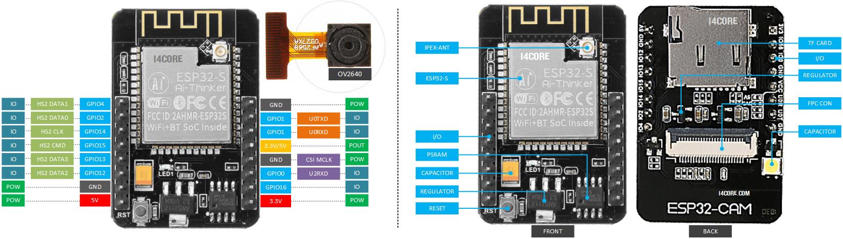
This one is low prize, ready to use and programmable module
I refer to randomnerdtutorials to learn how to use it. so here I repeated same experiment given there using my devices
.jpg)
.jpg)
.jpg)
Here I have used my FTDI board made by me in electronic production weeks. you can check out on my assignments page.
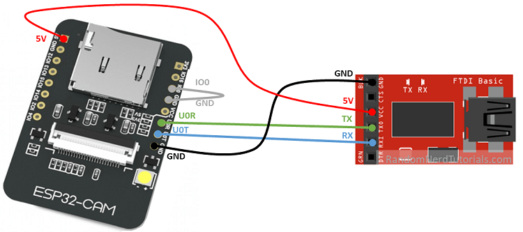
Connection are same as given in image
It need library to be install in arduino ide to get into use this module. you will find all step on given tutorial link
After installation you can go ahead with cam web server example code with little modification in it for device I using here
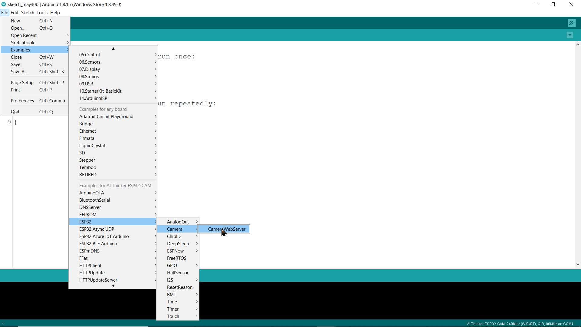
Here I am using AI_thinker camera module. you need to put your wifi username and password
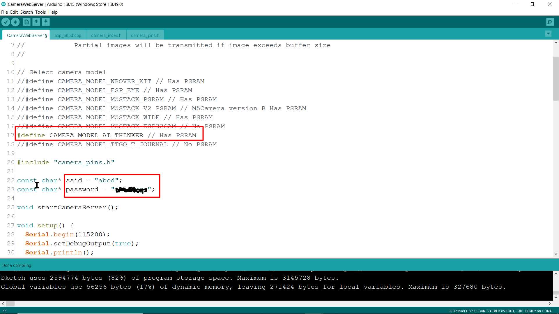
Selecting AI Thinker ESP32-CAM board
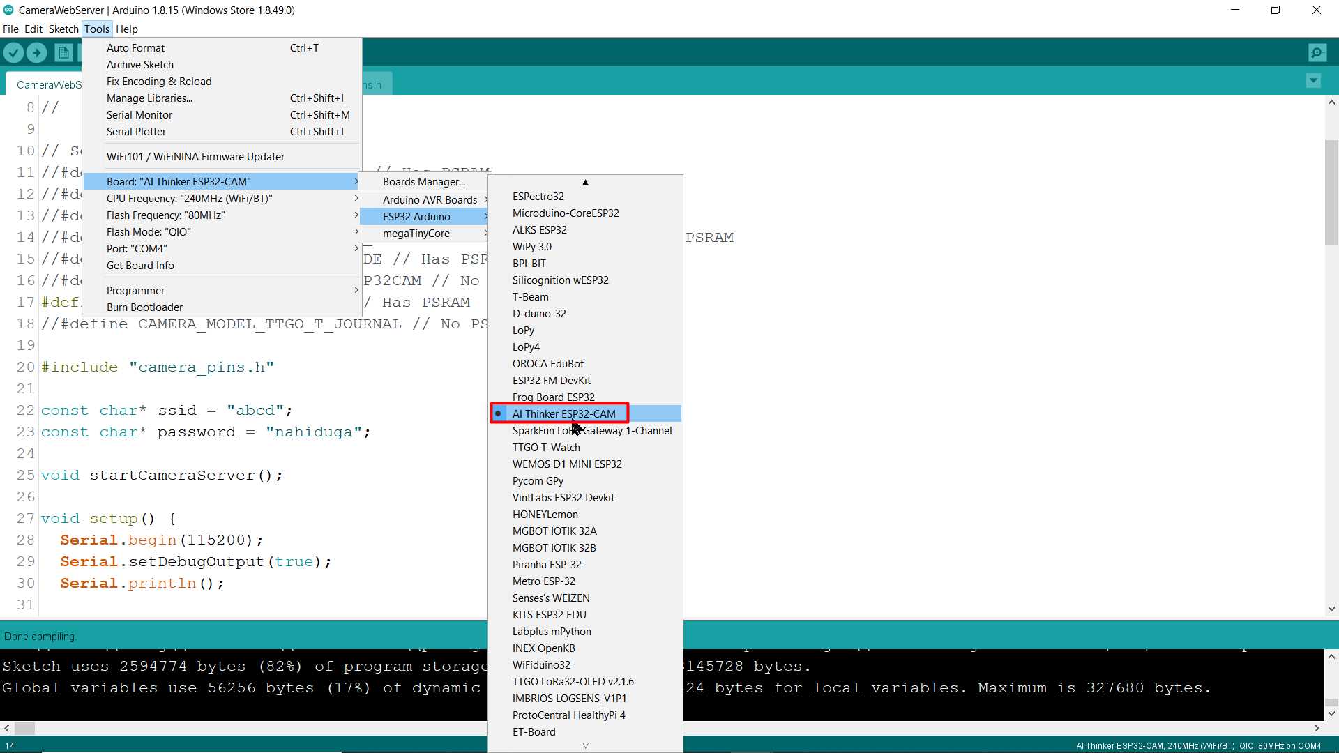
Next after completing all above stuff and uploading code in board first we need to note ip address show up in serial monitor
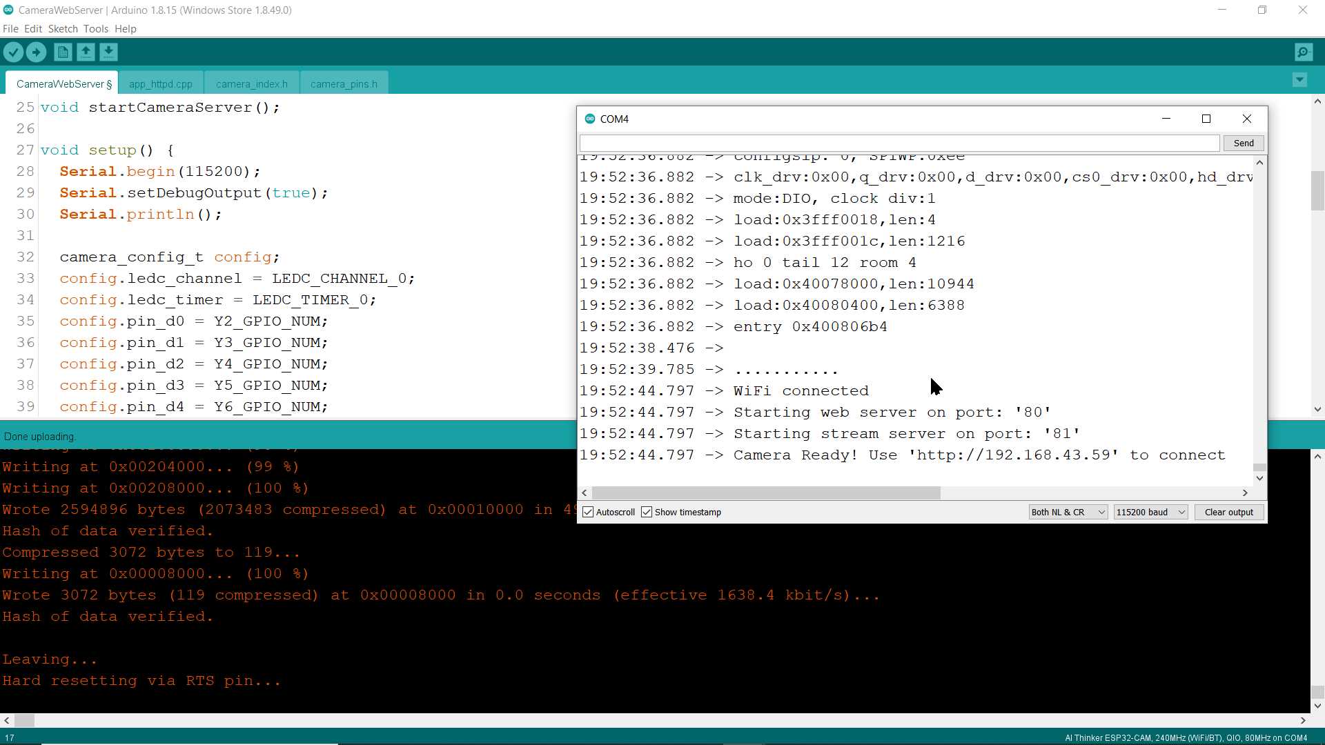
putting noted ip in browser will appear web interface for controlling and observing through esp32 camera
.jpg)
Here we have done with example that give a idea of how it work
ESP32 Board
Next moving to make my own esp32 board
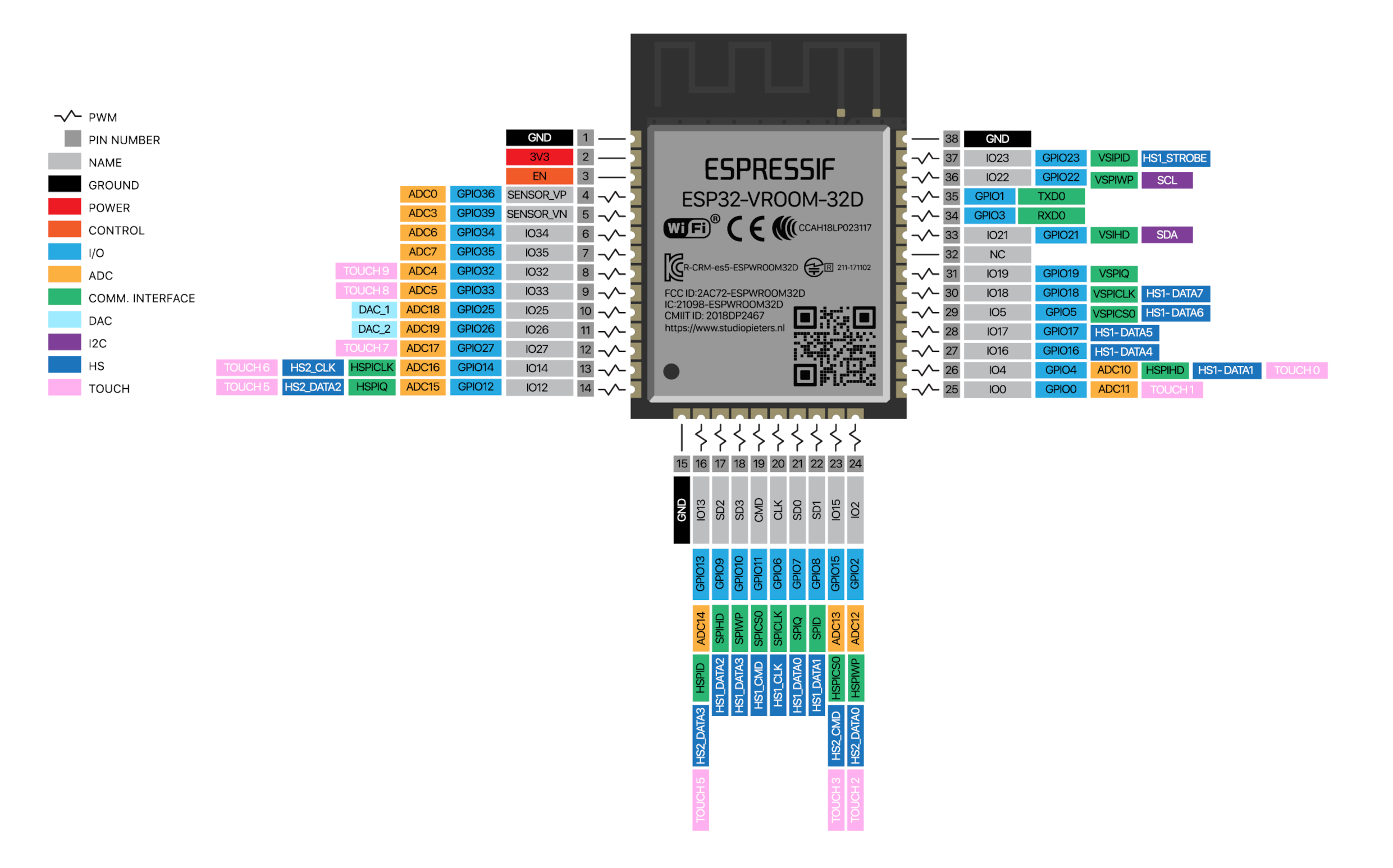
I refer ESP32 Pinout Reference: Which GPIO pins should you use? online to sure I am using right pins for my project
.jpg)
.jpg)
.jpg)
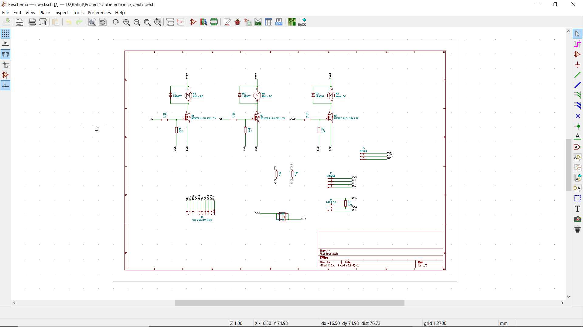
This is my design for my esp32 board
.jpg)
.jpg)
Completed my desiging part this but not got time to actually make it test it so I have took this work and continue in output device week assignment
.jpg)
.jpg)
...continued after 2 week
So I have changed design of above mentioned esp32board you can find new design on output device week
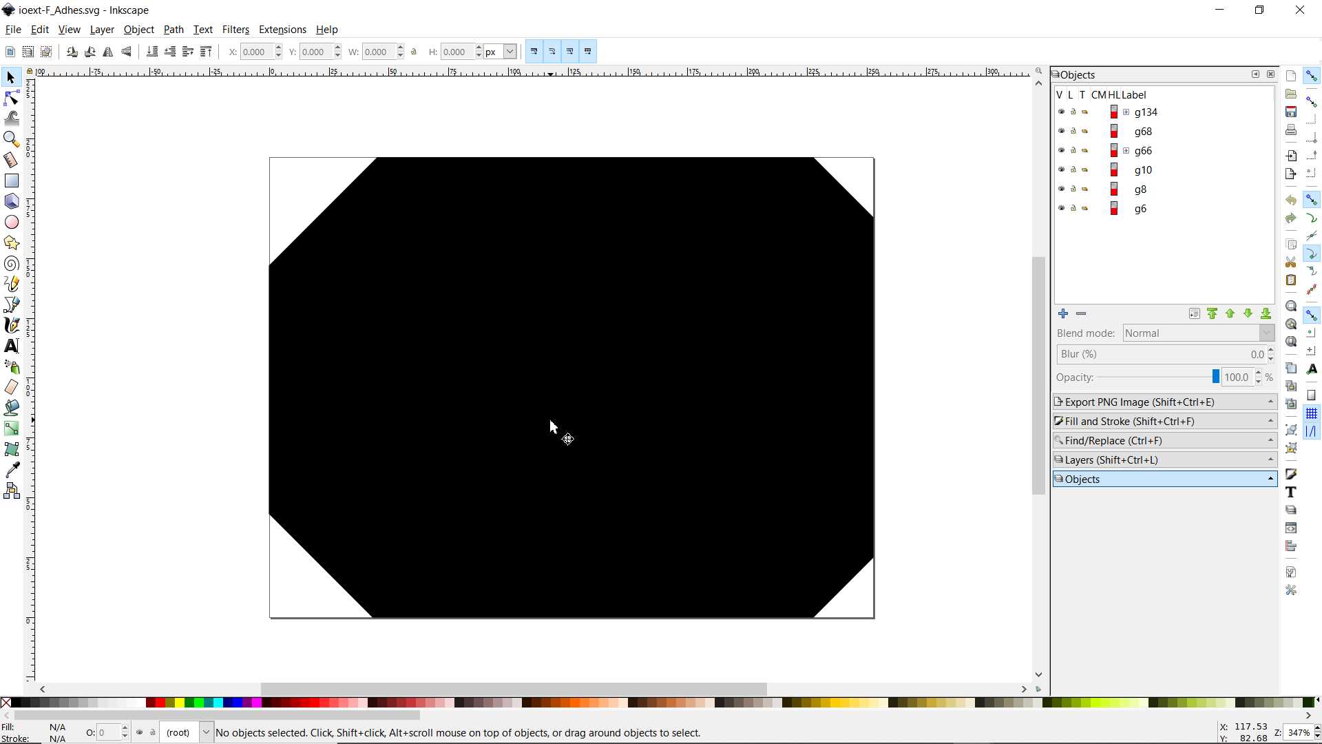
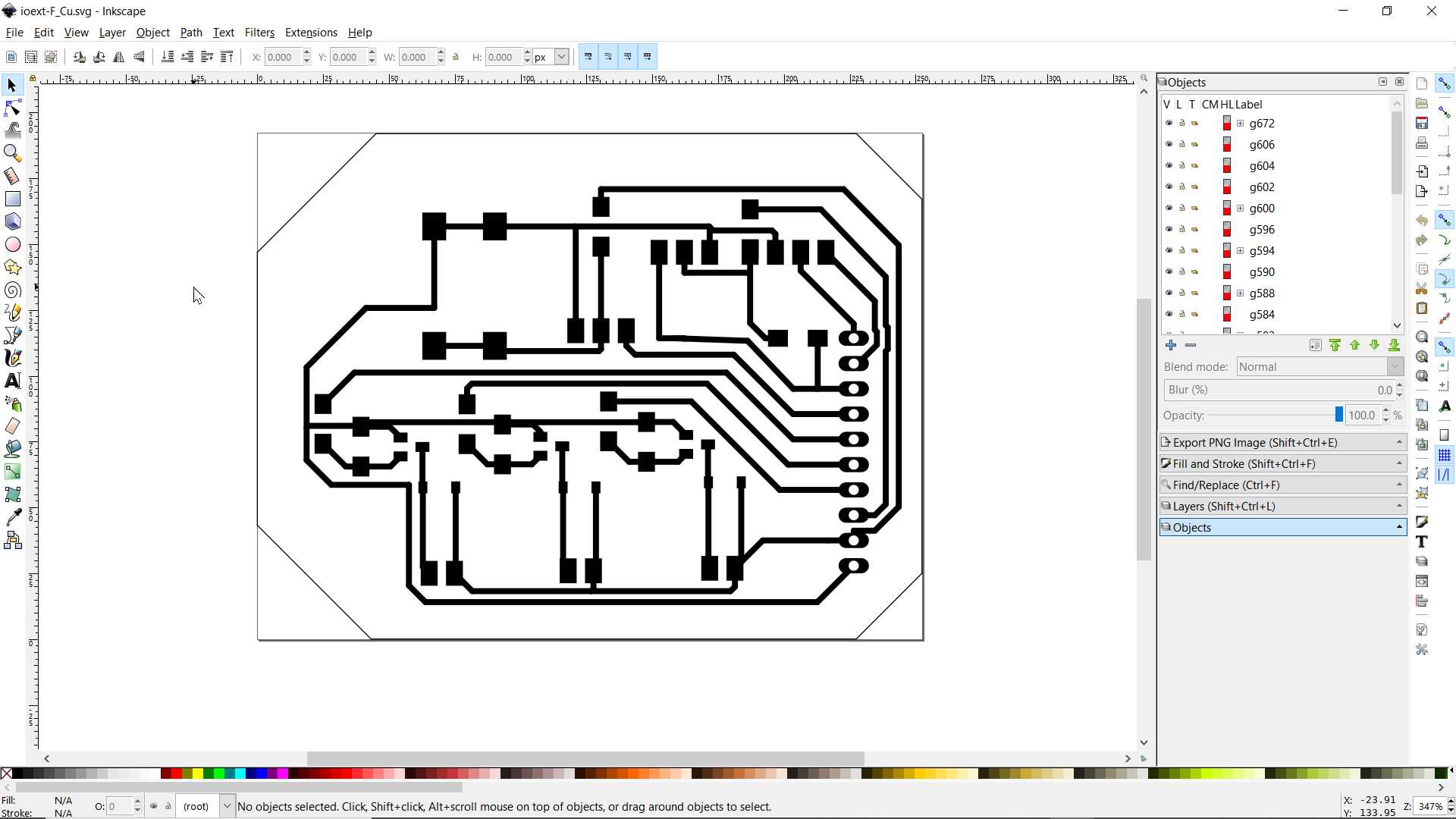
This assignment I continued after output week and when final project was near so I made board that have input and output attachment both. This is my final board that I have use in my final project Grocubator
So here I going to take test of input device. Data will be show on Interface I made in my interface and application week.
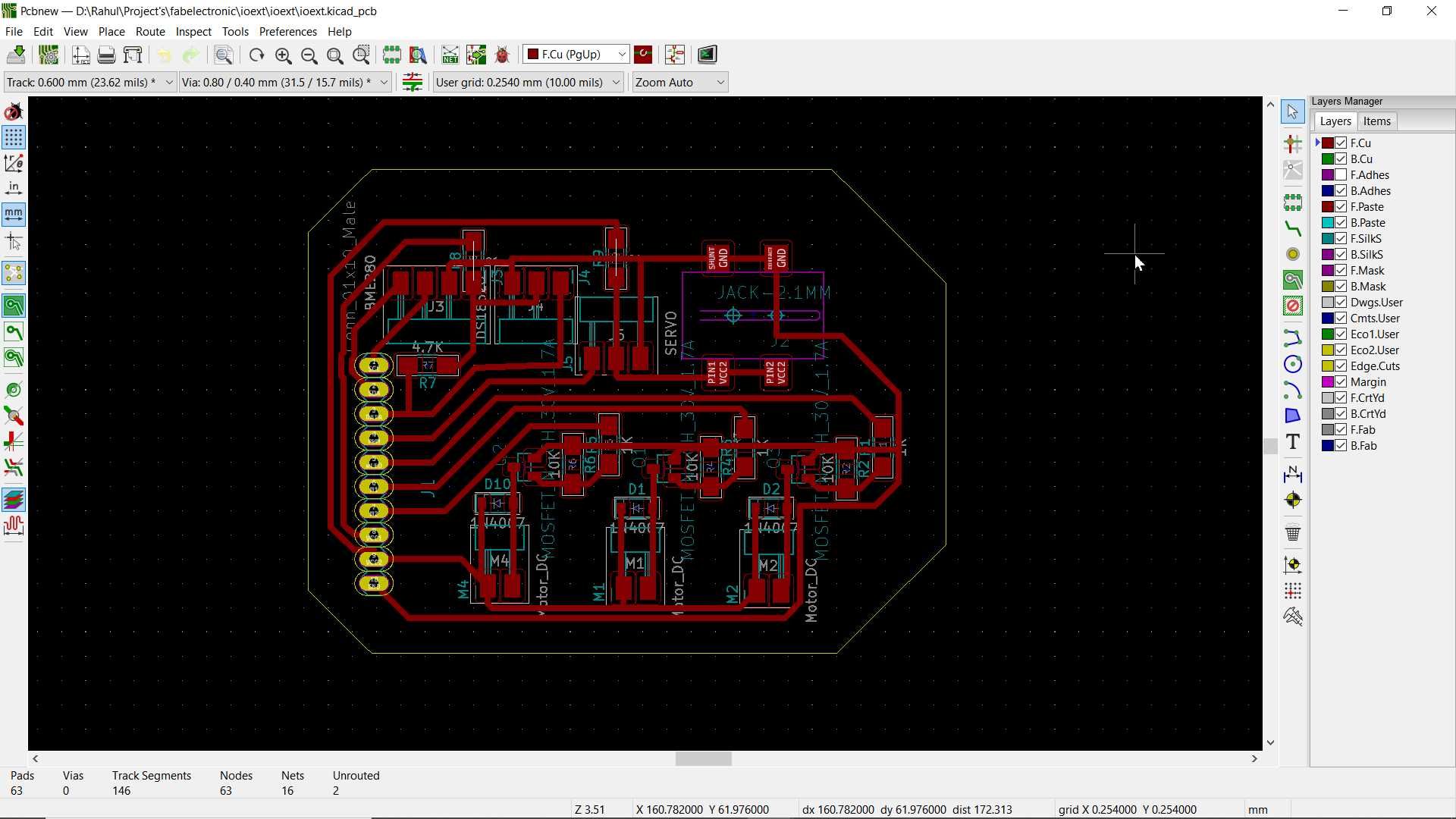
One good thing happen in rush I should mention here was that I printed my design invert. This made my driver board to overlap main board
I have not fixed it I let it be because that also going to work only issue with mosfet connection but I solved it by soldering it up side down and another was power jack that also solved
List of Components
- 3 x NDS355AN
- 3 x 1N4007 diode
- 3 x 100 ohms resistor
- 3 x 10K ohms resistor
- 1 x 2.1mm Power jack
- 1 x 4.7k ohms resistor
- 2 x 0 ohms resistor
- 1 x male header 1x10 pins
- 1 x male header 1x4 pins
- 3 x male header 1x2 pins
- 2 x male header 1x3 pins
Here one main board with esp32 and other one is driver board or extension board for connecting Input and Ouput devices
.jpg)
.jpg)
.jpg)
.jpg)
.jpg)
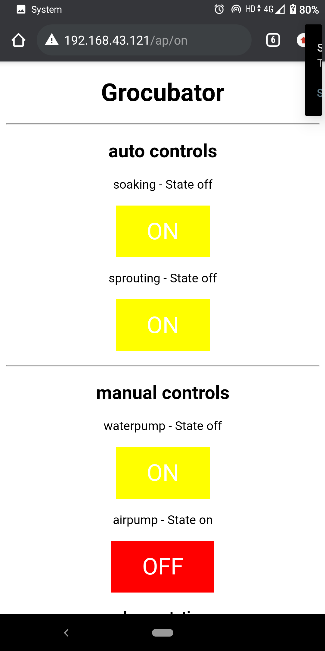
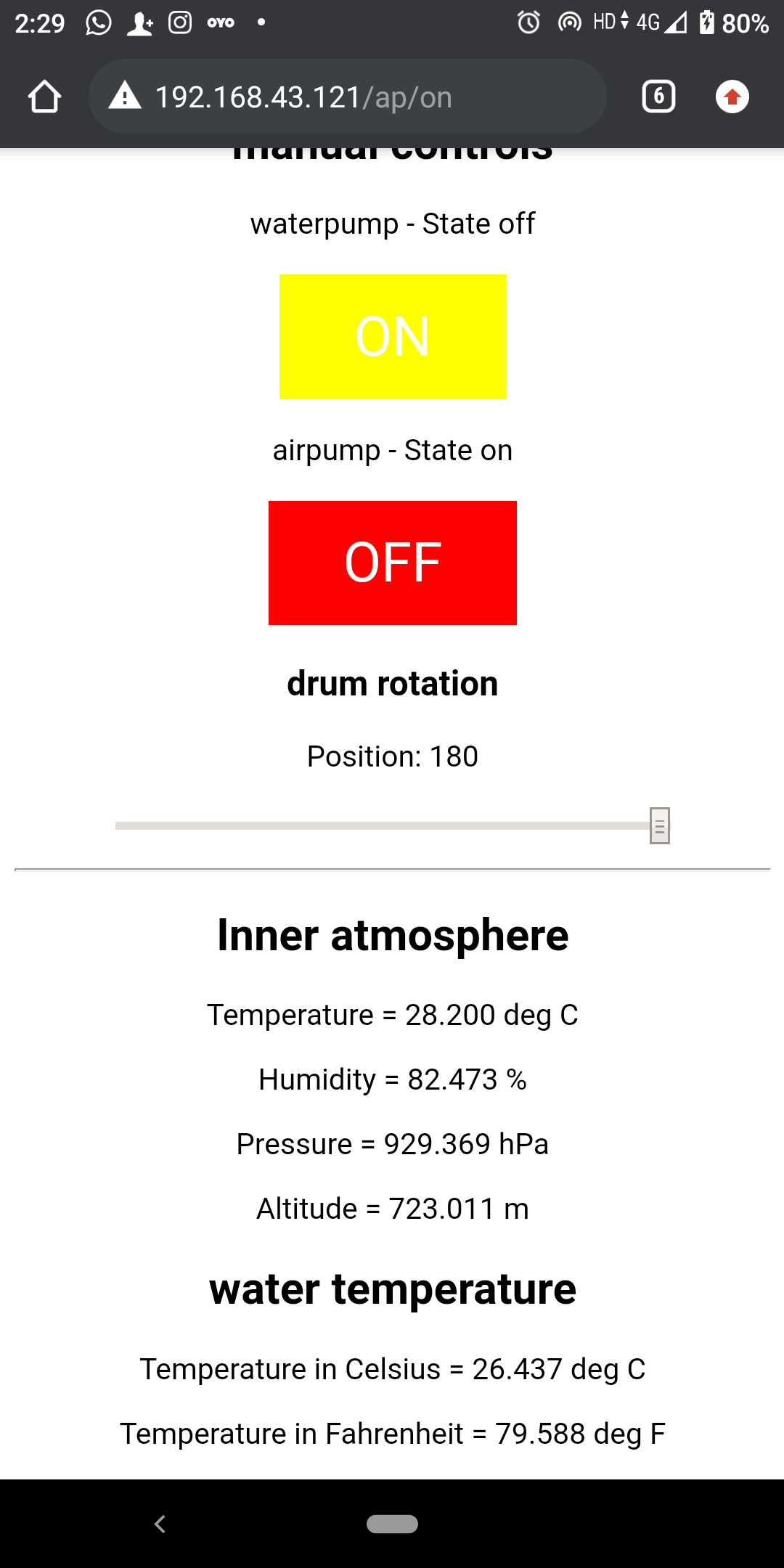
Here is interface to know more visit Interface and application week assignment and It show sensor reading
Learning Outcomes:
In input device week I used BME280 sensor and esp32 cam module because I was interest to know it. Since In input device week I have not completed all my work regarding to project because I was not sure of anything so later after passing 2 - 3 week as clarity came for what to do I started working and added those content in this assignment and it also because it started from here. Since I wanted to do free experiment but on reality check I have to work on my final project to keep project alive. I am happy with my work and since I like to do all experiments specially step response one. I will definately will do all in my personal time maybe after fab academy :)