Output Devices
Testing out actuators
Intro.
Now it been long time in Fabacademy and till now I had lot of experiment with electronic, machine and designing. Now in further journey I have to work with my final project idea "So much to do and so little time". So from Input devices week I began with my final pcb designing and now in this week I will work on output component of my finalproject which is some motors and leds.
.jpg)
Week Task:
Individual assignment:
add an output device to a microcontroller board you've designed,
and program it to do something
Group assignment:
measure the power consumption of an output device
Group assignment: summary
In group assignment each one of us tested power consumption of their output devices. to know more visit group assignment
I going use some motors in my project I will make driver circuit for it. So to know total consumption of power by motor will helpful in designing it circuit.
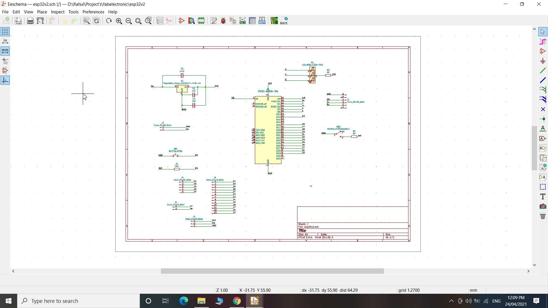
Final Project Board - ESP32
...continued from Input device week
Since this board is double sided printing it became challenging. last time I try milling double side board but getting right alignment for holes was effort taking and wasting of resources so I thought to print two pcb and after it done stick them together accordingly since alignment can be corrected while sticking.
.jpg)
.jpg)
after milling and Cutting, I done holes through vias and later I found vias sizes was bit smaller hence while drilling it trim off pads but some how I manage it.
.jpg)
.jpg)
things went okay after holes I matchup board stick it with glue and using old resistor wires in vias I made solder and made electrical contact with no more technical issue but board was not looking good to go with it in finalproject. Hence I discard it and started to improve my design.
.jpg)
#second attempt
List of Components
- 1 x ESP32-WROOM_32D
- 1 x AMS1117 3.3v regulator
- 1 x smd toggling switch
- 1 x smd push button
- 1 x RGB LED common anode
- 1 x 10k ohms resistor
- 2 x 0 ohms resistor
- 2 x 1uF capacitor
- 1 x 10uF capacitor
- 1 x male header 1x16 pins
- 1 x male header 1x6 pins
- 2 x male header 1x2 pins
- 1 x male header 1x5 pins
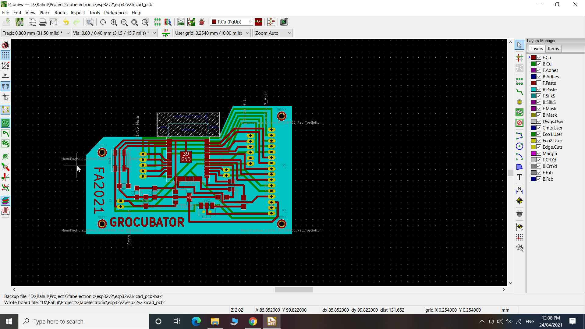
so next I corrected my design and this time I have not use vias to make electrical contact in different place instead of it I hack through hole header footprint and male header to make front and back contact.
.jpg)
.jpg)
Soldering was very easy compare to last one and final look looks clean
.jpg)
.jpg)
So here is the arduino ide code for RGB led changing colors. I have use analog/PWM output to make as many colors possible with RGB LED
const int red = 5;
const int blue = 2;
const int green = 4;

// setting PWM properties
const int freq = 5000;
const int ledChannel = 0;
const int resolution = 8;
const int spd = 10;


void leds_init() {
   // configure LED PWM functionalitites
  ledcSetup(ledChannel, freq, resolution);
  ledcSetup(ledChannel+1, freq, resolution);
  ledcSetup(ledChannel+2, freq, resolution);
  ledcAttachPin(red, ledChannel);
  ledcAttachPin(green, ledChannel+1);
  ledcAttachPin(blue, ledChannel+2);
}

void led() {
  ledcWrite(ledChannel, 255);
  ledcWrite(ledChannel+1, 255);
  ledcWrite(ledChannel+2, 255);


  for(int dutyCycle = 0; dutyCycle <= 255; dutyCycle++){
    // changing the LED brightness with PWM
    ledcWrite(ledChannel, dutyCycle);
    ledcWrite(ledChannel+1, 255-dutyCycle);
    ledcWrite(ledChannel+2, dutyCycle);
    delay(spd);
  }
  for(int dutyCycle = 0; dutyCycle <= 255; dutyCycle++){
    // changing the LED brightness with PWM
    ledcWrite(ledChannel+1, dutyCycle);
    ledcWrite(ledChannel, dutyCycle);
    ledcWrite(ledChannel+2, 255-dutyCycle);
    delay(spd);
  }

  for(int dutyCycle = 0; dutyCycle <= 255; dutyCycle++){
    // changing the LED brightness with PWM
    ledcWrite(ledChannel+2, dutyCycle);
    ledcWrite(ledChannel+1, dutyCycle);
    ledcWrite(ledChannel, 255-dutyCycle);
    delay(spd);
  }

}

void setup() {
  leds_init();
  //white light
  ledcWrite(ledChannel, 240);
  ledcWrite(ledChannel+1, 200);
  ledcWrite(ledChannel+2, 100);
  delay(2000);

}

void loop() {
  led();
}
Uploaded code using usb to serial converter made in electronic Production week. ESP32 chip use Rx and Tx line to take code.
Board working as I wanted it to later I have done many other experiment with this board with no issue.
Later found a mistake on my design I misconnected 10uf capacitor to 3.3v and 5v. Since both side were positive it have no role in circuit and it have not even created any problem but it was technical error that I fixed in my design
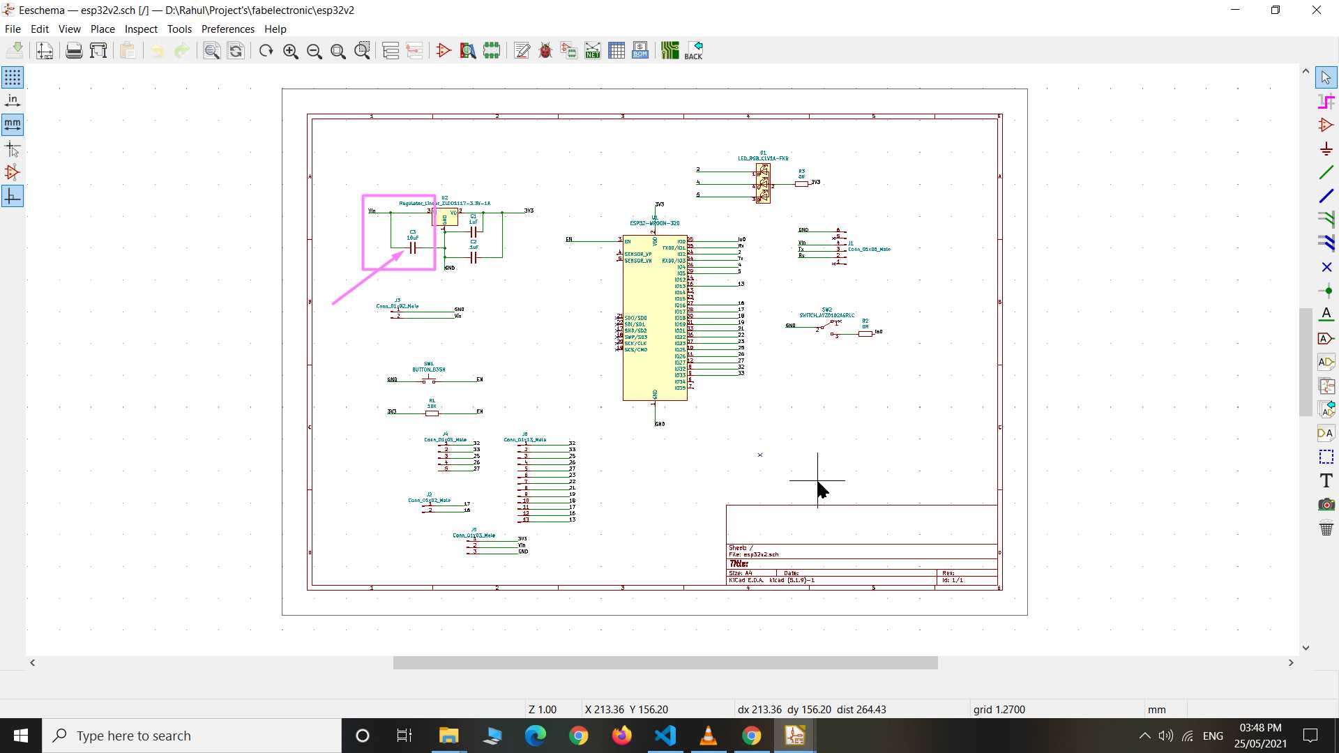
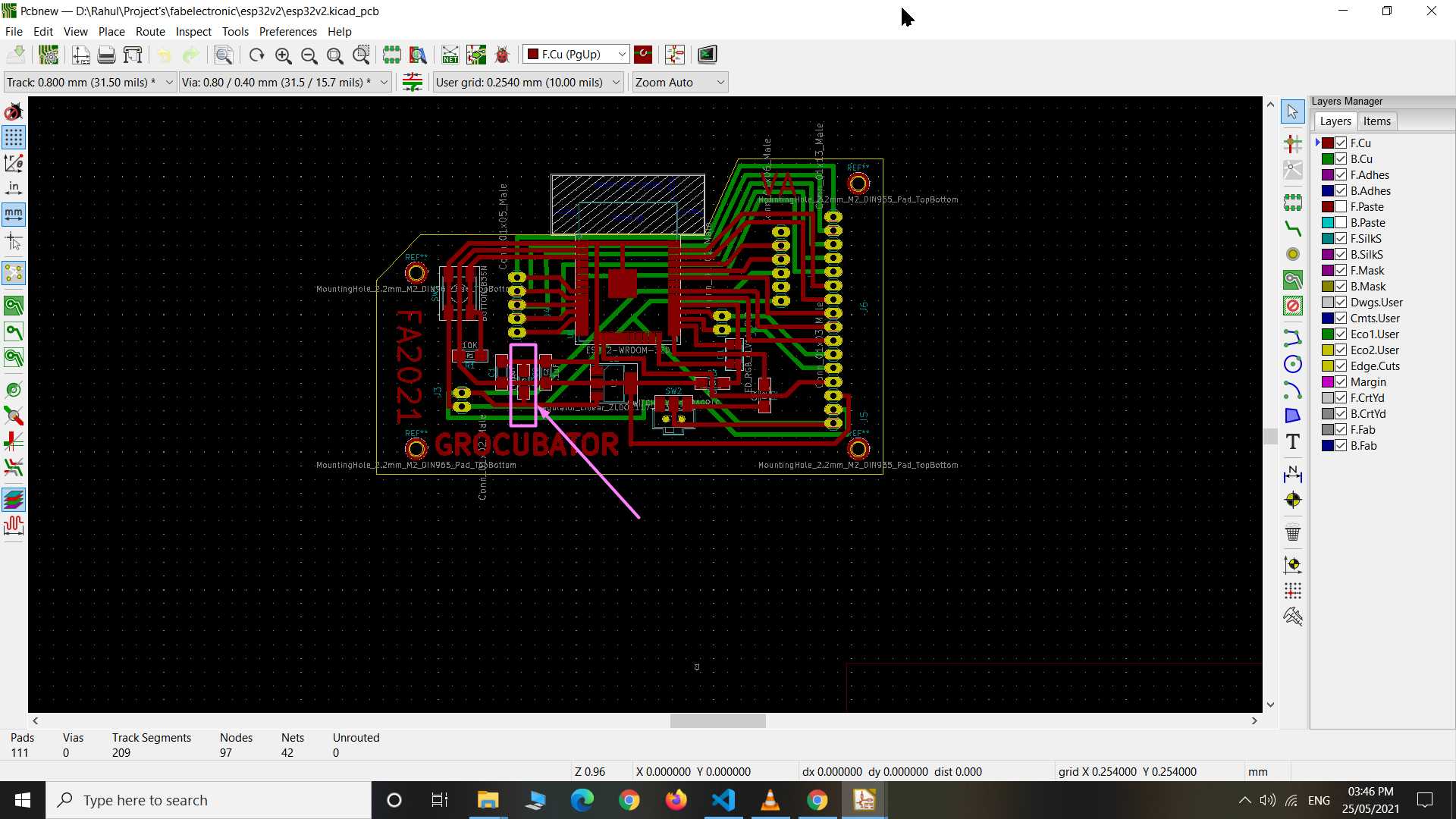
but I thought not to mill pcb again so I manage to fix this manually on my pcb. I desolder capacitor from front and solder it on back side on Vin and Gnd
.jpg)
.jpg)
It was working fine before also and after correction still working well too...
Output device board
So for my final project I need motors controlled so I made my version of motor controller shield for my ESP32 board that I made recently.
Here I have used H-bridge ic to control forward / reverse rotation of brush DC motor and I have also used mosfet as a switch to turn on/off waterpump
Structure of an H-bridge (highlighted in red)

The term H-bridge is derived from the typical graphical representation of such a circuit. An H-bridge is built with four switches (solid-state or mechanical). When the switches S1 and S4 are closed (and S2 and S3 are open) a positive voltage is applied across the motor. By opening S1 and S4 switches and closing S2 and S3 switches, this voltage is reversed, allowing reverse operation of the motor. wikipedia"
The two basic states of an H bridge

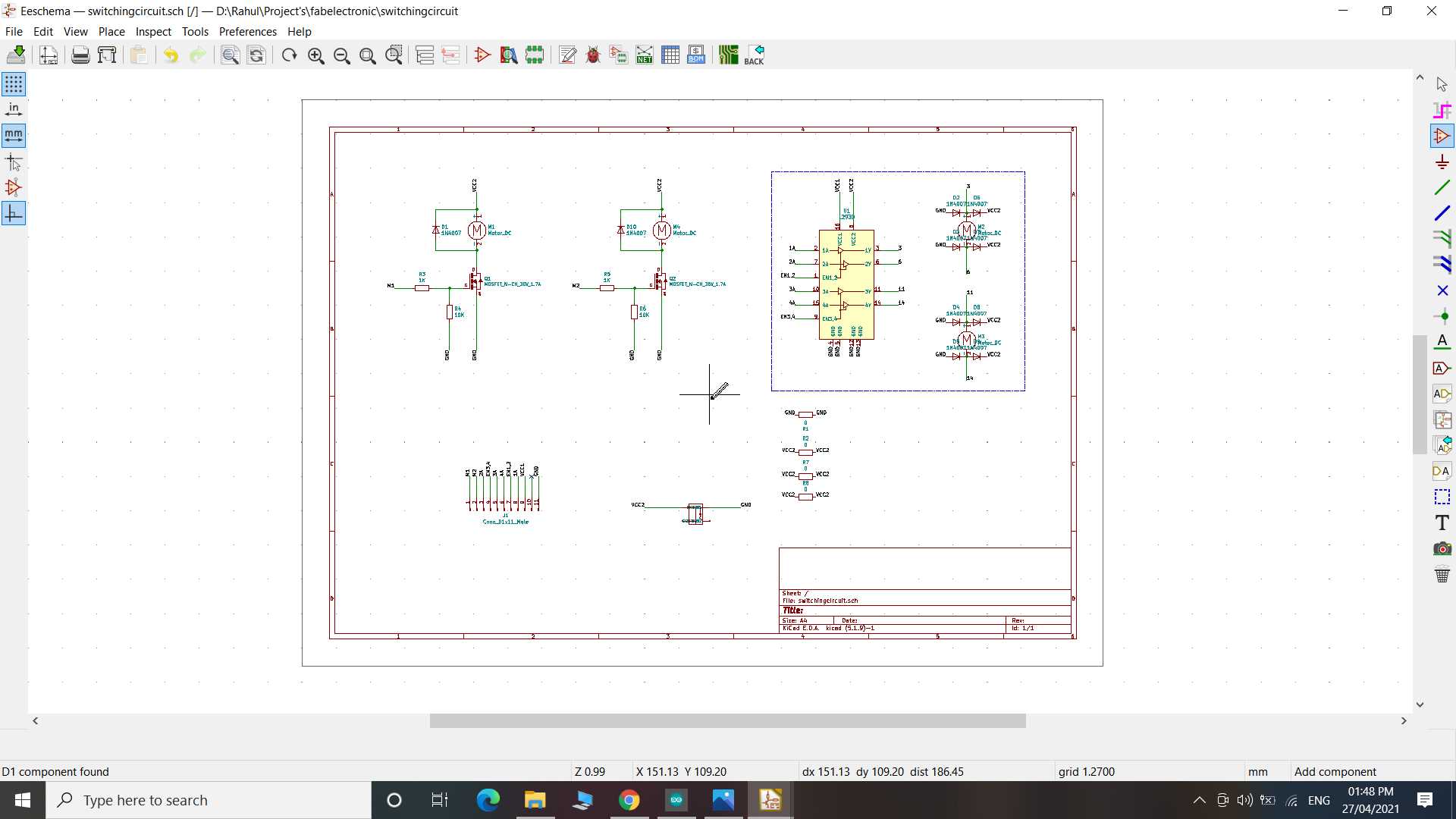
I have used Lm293D H-bridge ic for this purpose
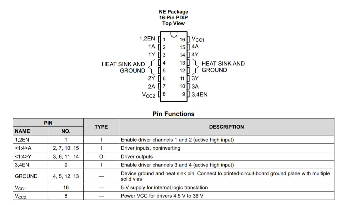
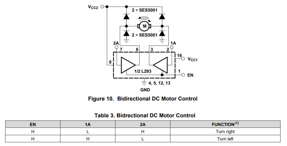
and configure Lm293D to control two dc motor using below electronic configuration
MOSFET switch
The metal–oxide–semiconductor field-effect transistor (MOSFET, MOS-FET, or MOS FET), also known as the metal–oxide–silicon transistor (MOS transistor, or MOS), is a type of insulated-gate field-effect transistor that is fabricated by the controlled oxidation of a semiconductor, typically silicon. The voltage of the covered gate determines the electrical conductivity of the device; this ability to change conductivity with the amount of applied voltage can be used for amplifying or switching electronic signals. wikipedia
Here In this board I am adding N-channel MOSFET NDS355AN
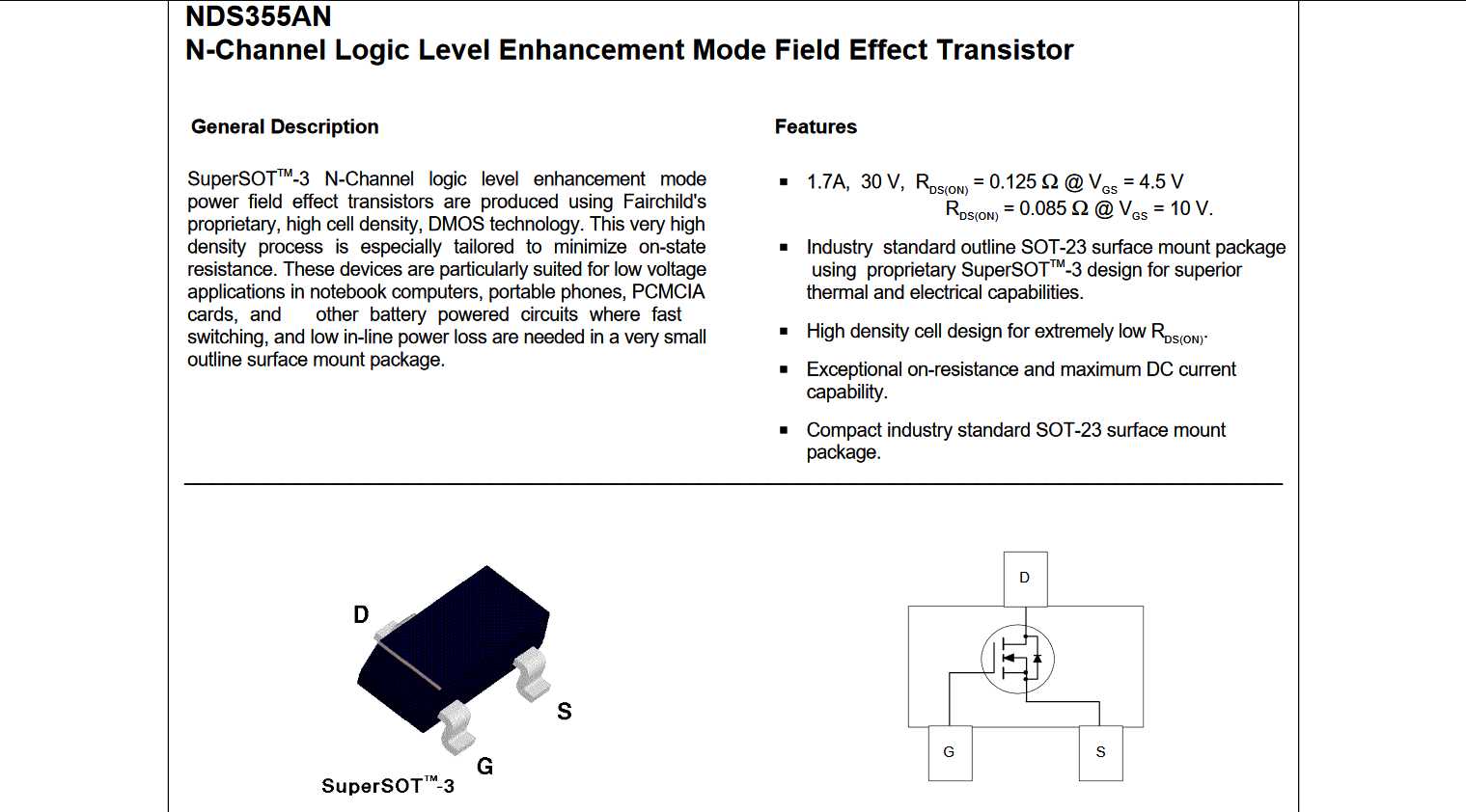
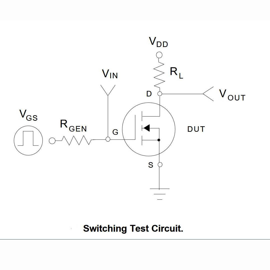
I making mosfet switching circuit that given below...
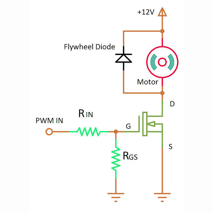
In second image you see diode is added around motor this known as Flywheel Diode
A flyback diode is a diode connected across an inductor used to eliminate flyback, which is the sudden voltage spike seen across an inductive load when its supply current is suddenly reduced or interrupted. It is used in circuits in which inductive loads are controlled by switches, and in switching power supplies and inverters.This diode is known by many other names, such as snubber diode, commutating diode, freewheeling diode, suppressor diode, clamp diode, or catch diode. wikipedia
This diode is use in H-bridge circuit too because we controlling motor there too
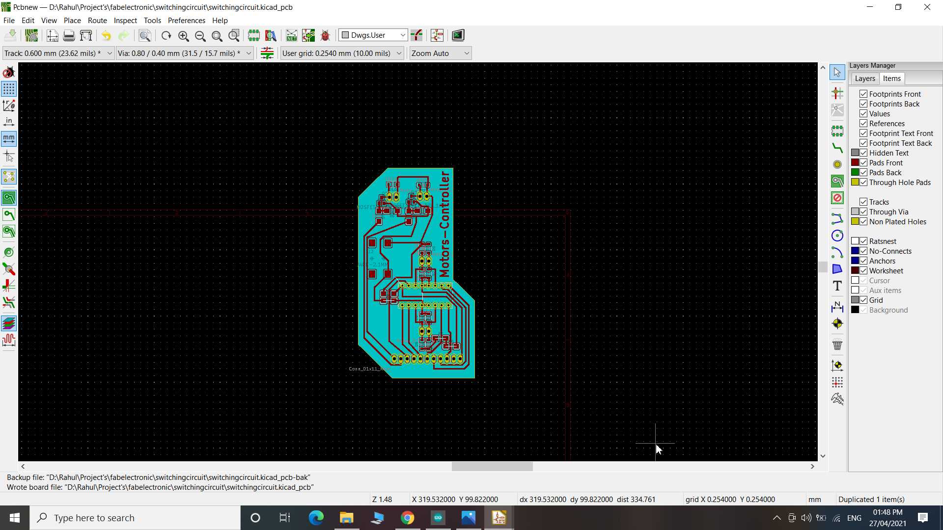
Motor controller board
I design board using KiCad. I made this output device board as an extension of my ESP32 board. It have external powersupply port to power the motor. so here I am switching high power that needed for motor with low power signal for esp32 board.
.jpg)
List of Components
- 2 x NDS355AN
- 1 x Lm293D H-Bridge
- 1 x 2.1 mm power jack
- 10 x 1N4007 diodes
- 2 x 0 ohms resistors
- 2 x 100 ohms resistors
- 2 x 10k ohms resistors
- 1 x female header 1x11 pins
- 4 x male header 1x2 pins
after assembling
.jpg)
.jpg)
Here my code to drive motor
void setup() {
  pinMode(13, OUTPUT);
  pinMode(21, OUTPUT);
  pinMode(16, OUTPUT);
  digitalWrite(16,HIGH);

  pinMode(22, OUTPUT);
  pinMode(2, OUTPUT);
  pinMode(4, OUTPUT);
  pinMode(5, OUTPUT);
}


void loop() {
  digitalWrite(22, HIGH);
  delay(5000);
  digitalWrite(22, LOW);
  delay(1000);


  digitalWrite(13, HIGH);
  digitalWrite(21, LOW);
  delay(5000);
  digitalWrite(21, HIGH);
  digitalWrite(13, LOW);
  delay(5000);
  digitalWrite(2,HIGH);
  delay(1000);
  digitalWrite(4,HIGH);
  delay(1000);
  digitalWrite(5,HIGH);
  delay(1000);
  digitalWrite(2,LOW);
  delay(1000);
  digitalWrite(4,LOW);
  delay(1000);
  digitalWrite(5,LOW);
  delay(1000);
}
and Here the video of motor rotating. Since for now I have two motor to work with but my circuit can connect with four motors. It have H-bridge for two motor and switching circuit for two motor.
Learning Outcomes:
So this week I done simple progress toward my finalproject I made my esp32 circuit board and motor control board. The board design I continue making from Input device week failed so I well designed it again this week. I experiment with making double side pcb and It turn out masterpiece and I am happy with it. Yup! I have done mistake many time like first milling double sided pcb I lost alignment of front and back so I have used two single sided pcb and joined them, second I misconnected component that all I mentioned up in documents this because of rushing. I fixed it all and got good output result...