
Test the design rules for your 3D printer(s).
Link to Group Assignment Design and 3D print an object (small, few cm3, limited by printer time)
that could not be made subtractively.
3D scan an object (and optionally print it).
Assignment Requirement
Status
Linked to the group assignment page.
Completed
Explained what I learned from testing the 3D printers.
Completed
Documented how I designed and 3D printed your object and explained why it could not be easily made subtractively.
Completed
Documented how I scanned an object.
Completed
Included my original design files for 3D printing.
Completed
Included my hero shots.
Completed
3D printing is an additive manufacturing process that produces a physical object from a digital 3D image. Additive manufacturing is basically materials being added or deposited on the other like layering until the desired object is completed.
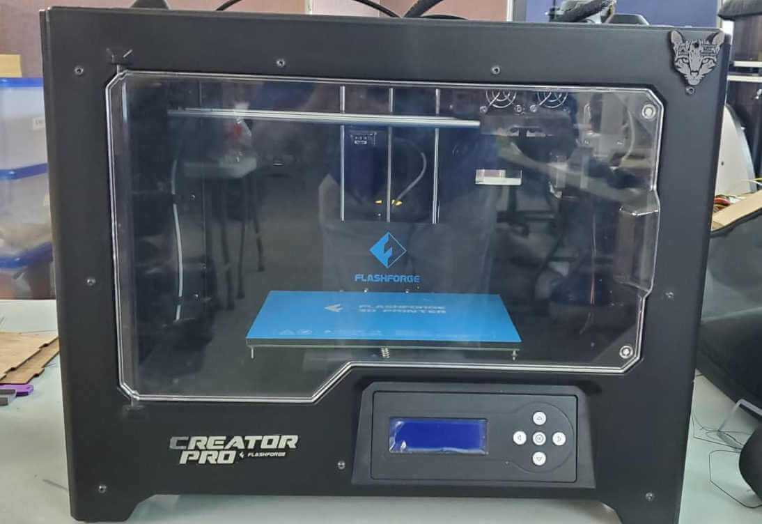
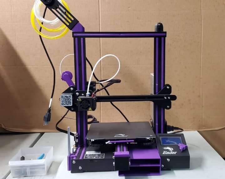
The three main 3D Printers we use at our lab are the Flashforge Creator Pro, Creality Ender 3 and Prusa MK3+. For this assignment I chose the Prusa MK3 since its quality prints surpased the other two as seen in the group assignment and with less work with regards to its print settings.
Flashforge Creator Pro
Creality Ender 3
Prusa MK3+

For this assignment I was required to 3D print an object that cannot be made subtractively. I decided to design a simple vase and 3D print using ABS plastic. ABS stands for Acrylonitrile Butadiene Styrene which is basically a thermoplast. It is ductile, lightweight and a fairly tough material that can be used for certain replacement parts.
I used FreeCAD to design my vase. I used the wrap process for this design. I first selected the Part Design workspace.
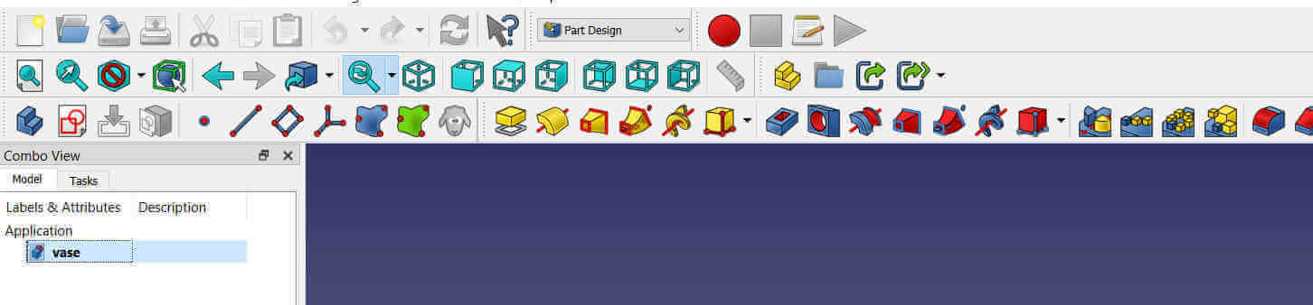
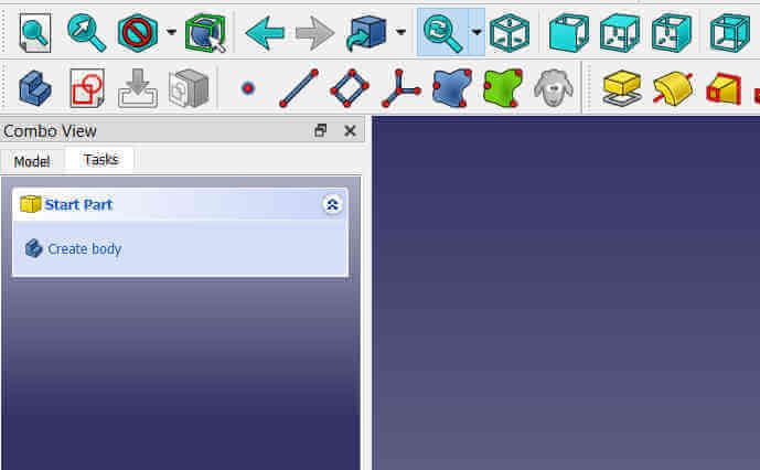
I clicked on the Create a New Part tool.
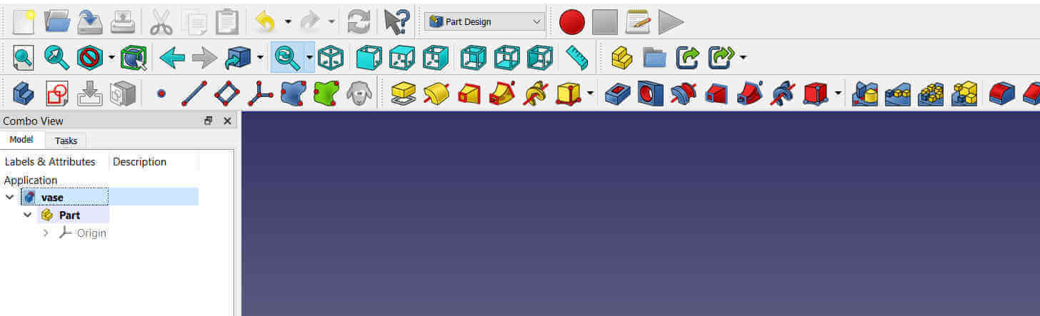
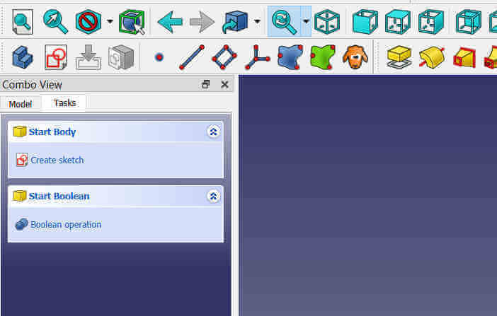
I then clicked Create body from the progress window to the left.
This allowed me to Create sketch.
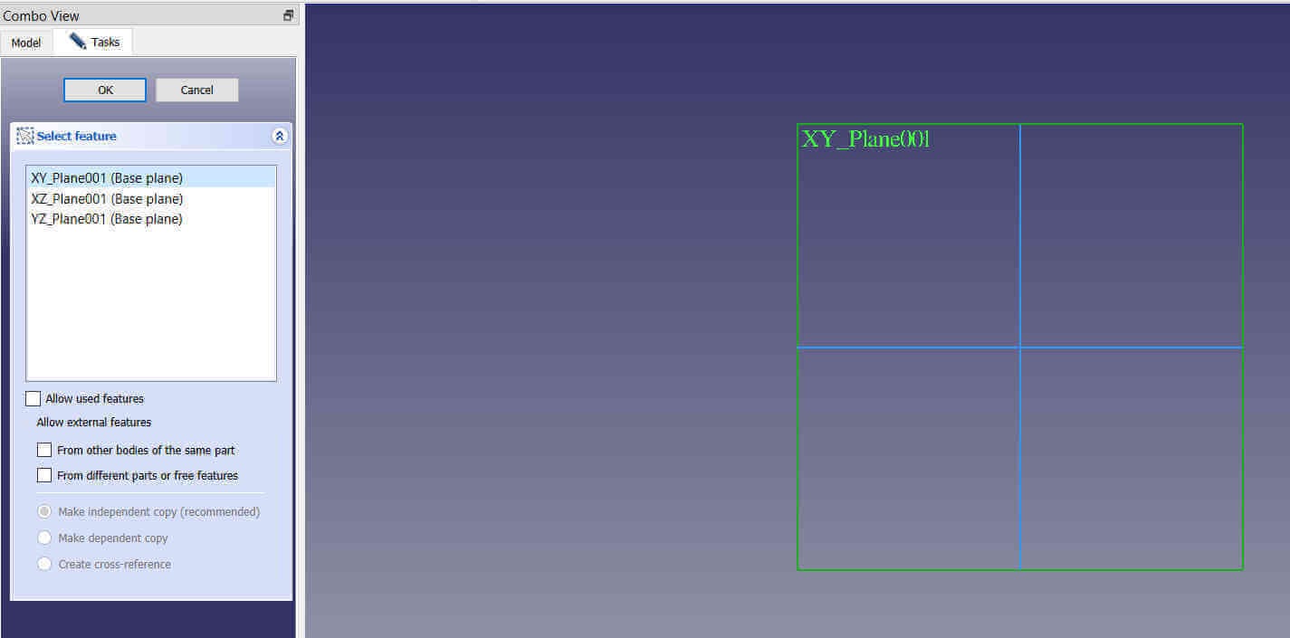
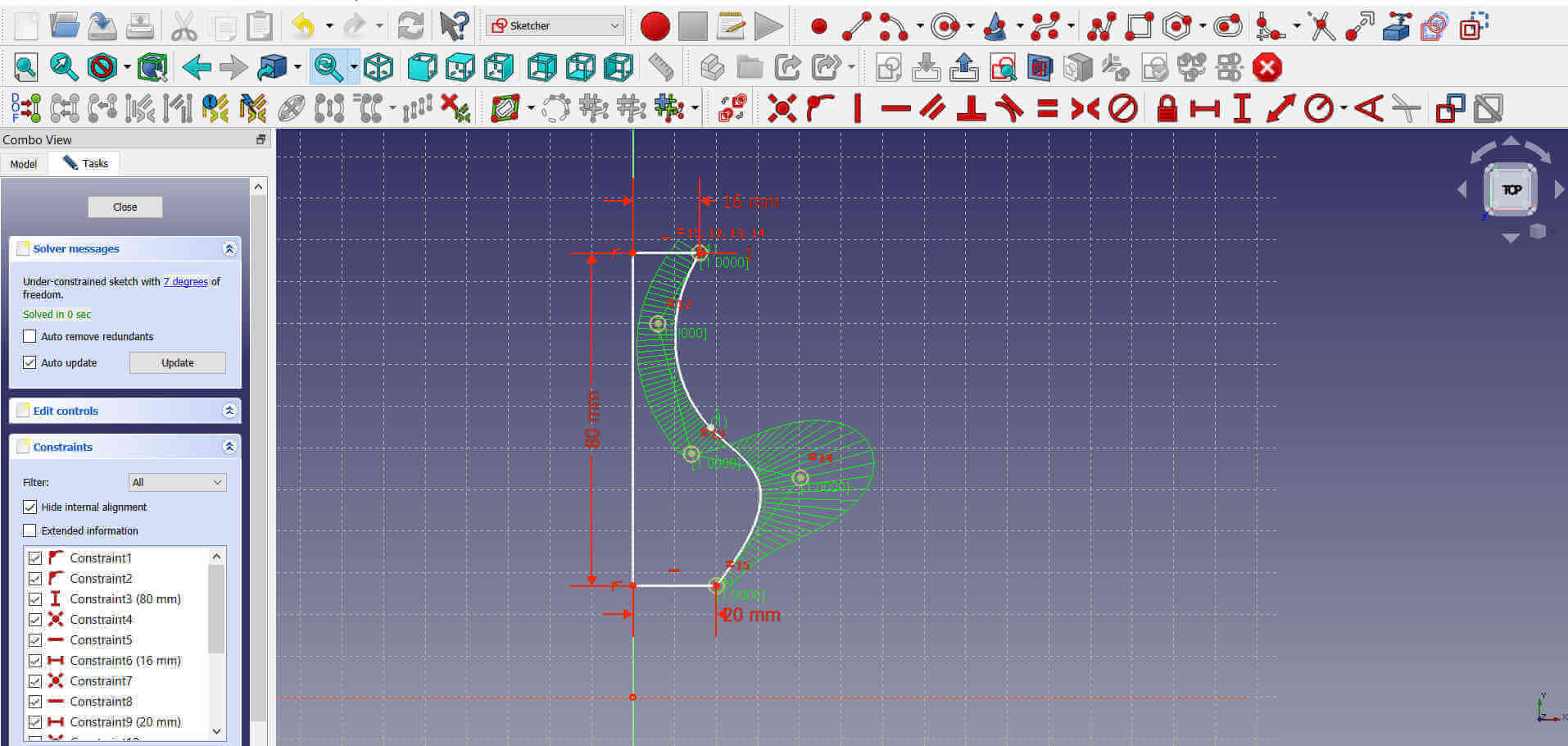
Upon selecting Create sketch, I was prompted to select the axis base plain. I chose the X,Y base plain mainly because this is the plain I mostly use so unconciously I clicked on it. Selecting the X,Y baseplain is not an issue, it just required me to rotate for printing, whereas if I had selected the X,Z or Y,Z baseplains my vase would have already been in the upright position.
I created a contrained vertical line attached to horizontal lines at both ends using the Create a line sketch tool. The vertical line was given a height of 80mm, the bottom horizontal 20mm and the top 16mm.
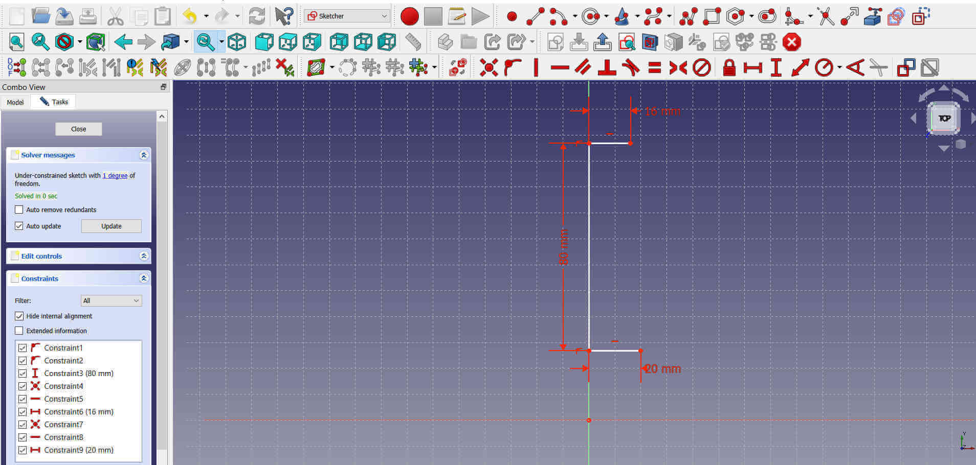
I then used the Create a B-spline tool to add the curved edge of the vase. So basically I sketched a half side of the vase.
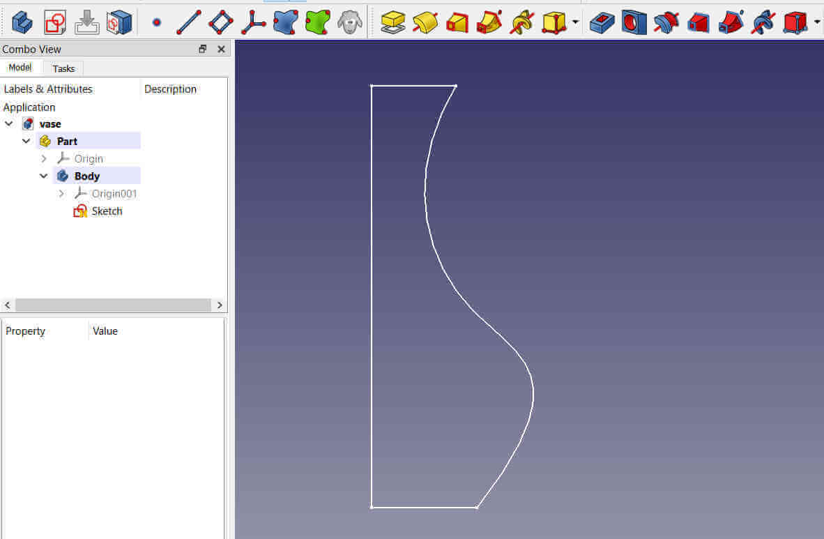
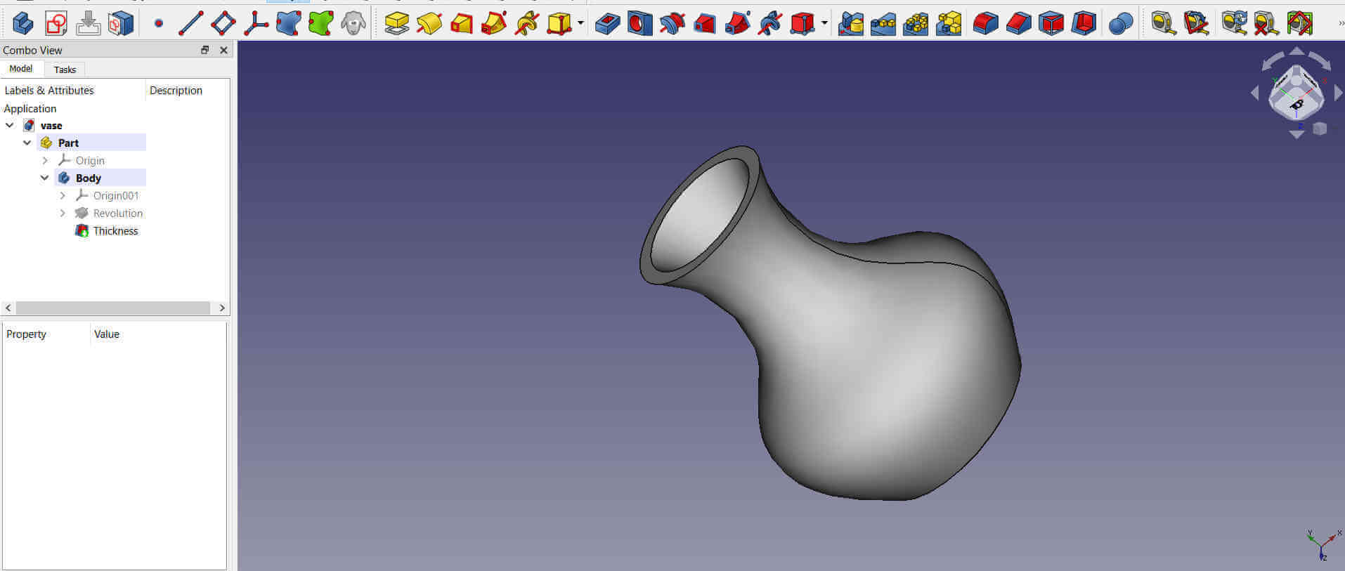
I closed the editting sketch window and from the progress window I selected the sketch from the list. I clicked on the Revolve a selected sketch tool and set the angle to 360 deg. This revolved the sketch giving it the rounded shape.
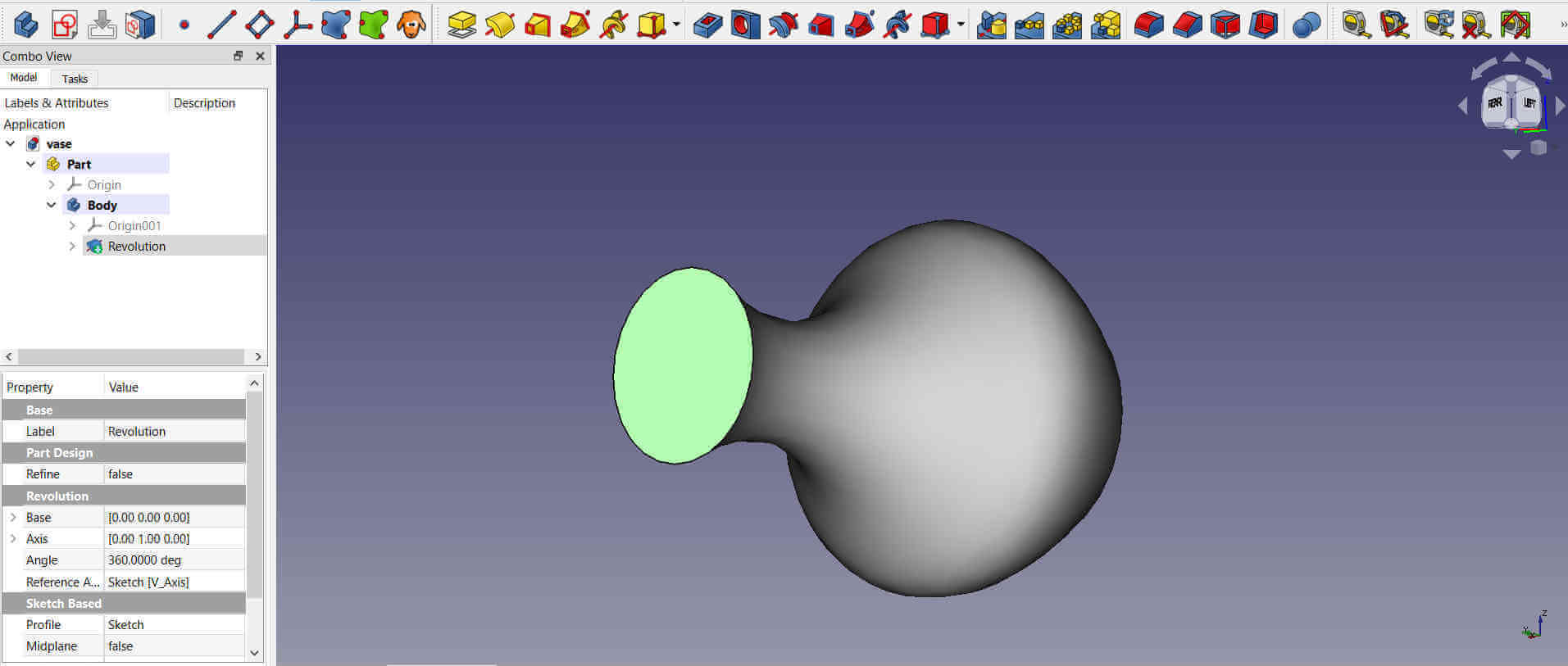
My vase was now a solid object but I needed to make the inside hollow. For this I used the Make a thick solid tool. I set the outter body thickness to 3mm.
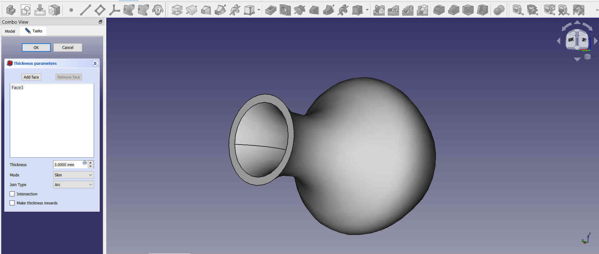
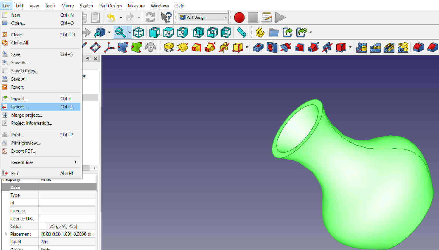
My vase was now ready so I highlighted it and from the Files menu tab I exported it as a .stl file. .stl is an acronym for stereolithography which is one of the most common 3D file format used in 3D printing process.
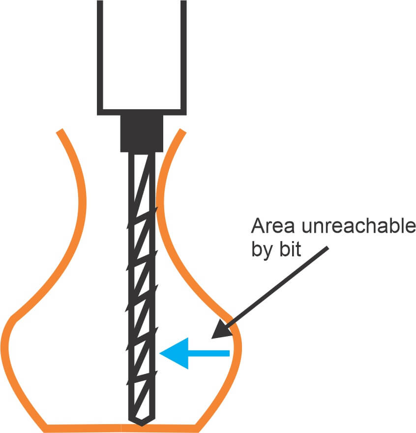
The following diagram shows areas that cannot be reached using a machine bit, therefore the vase could not be made from a subtractive process.
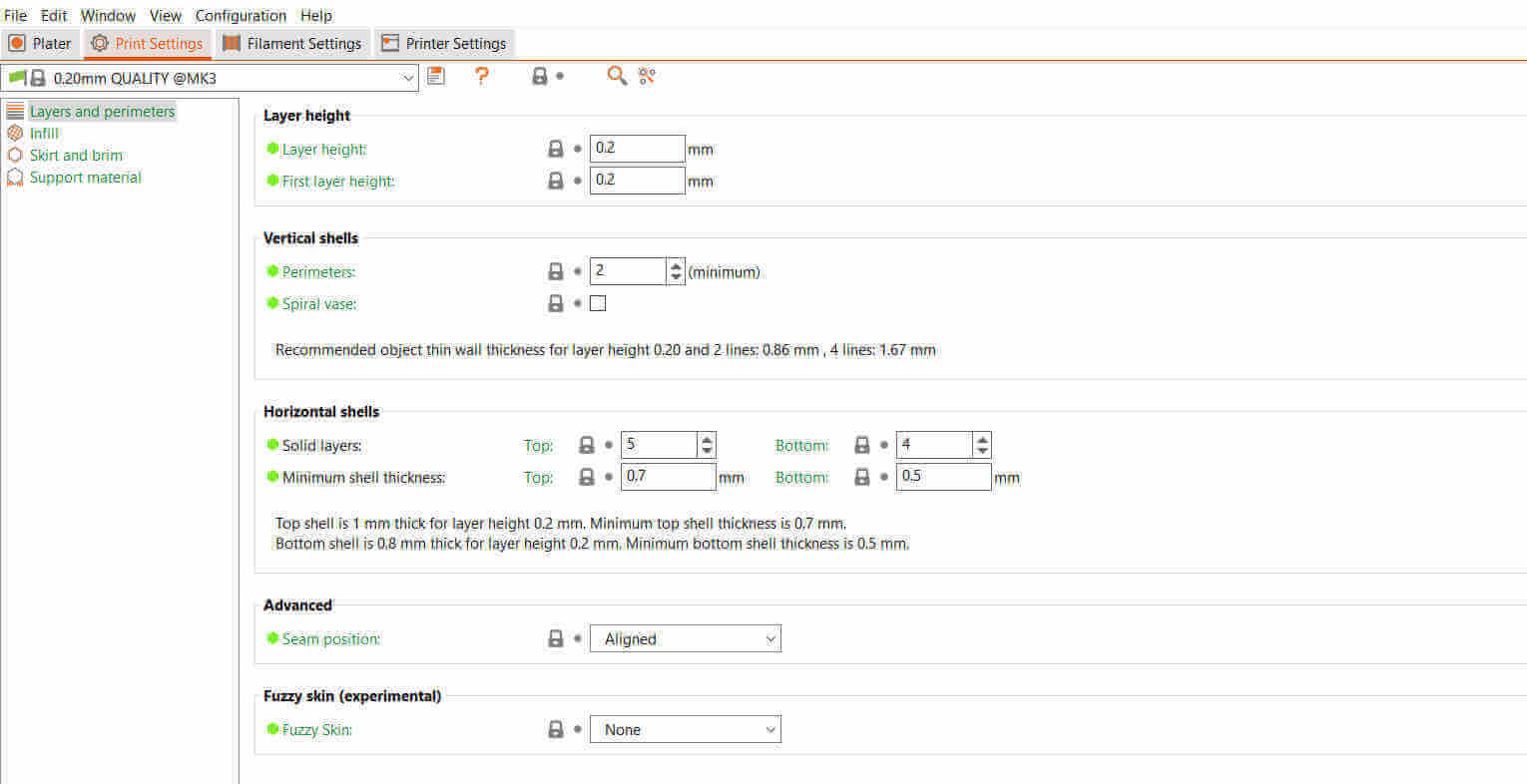
The .stl file was imported into Prusa Slicer. This is the software I used to prep the design before sending to the 3D printer. To the left is the bed display and to the right is some basic print settings. There are more advanced and detailed settings but those are more useful for more complex prints. To the top left are some detailed settings tabs also.
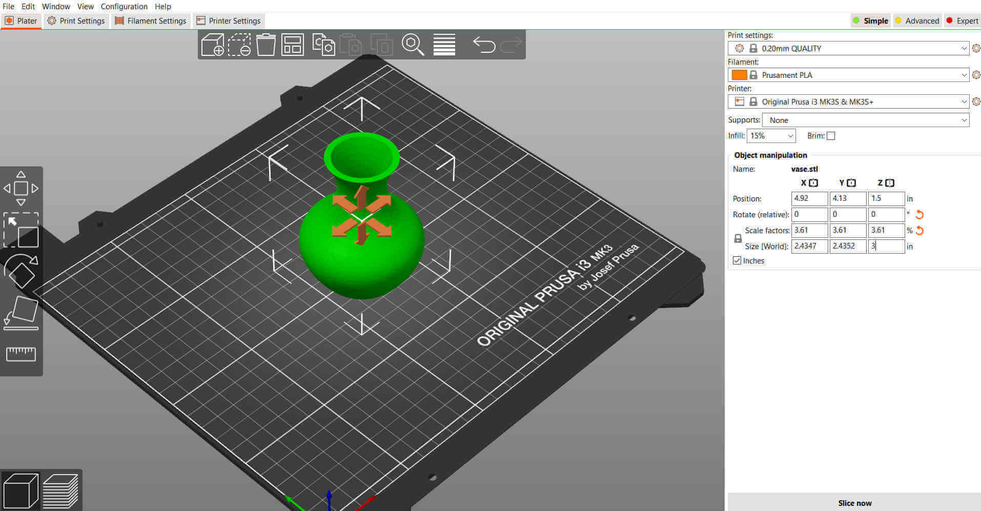
For the print settings I set the layer height to 0.2mm because I wanted a good quality print, however, the nozzle I used on the 3D printer was 0.2mm.
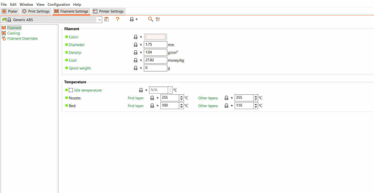
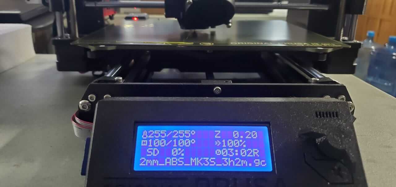
The default filament settings was set up for PLA. There was a list of filament types to choose from, each with their particular settings and also there was an option to add new filament profiles. I switched from PLA to ABS from Matterhackers. The recommended settings on the filament package for extruder temperature was 220 - 235 deg Celcius and bed temperature was 80 - 110 deg Celcius. I had to increase the extruder temperature to 255 deg Celcius because at 235 deg Celcius the layer bonding was weak. I assume this was due to the fact that we had the filament a very long time and it was not stored properly.
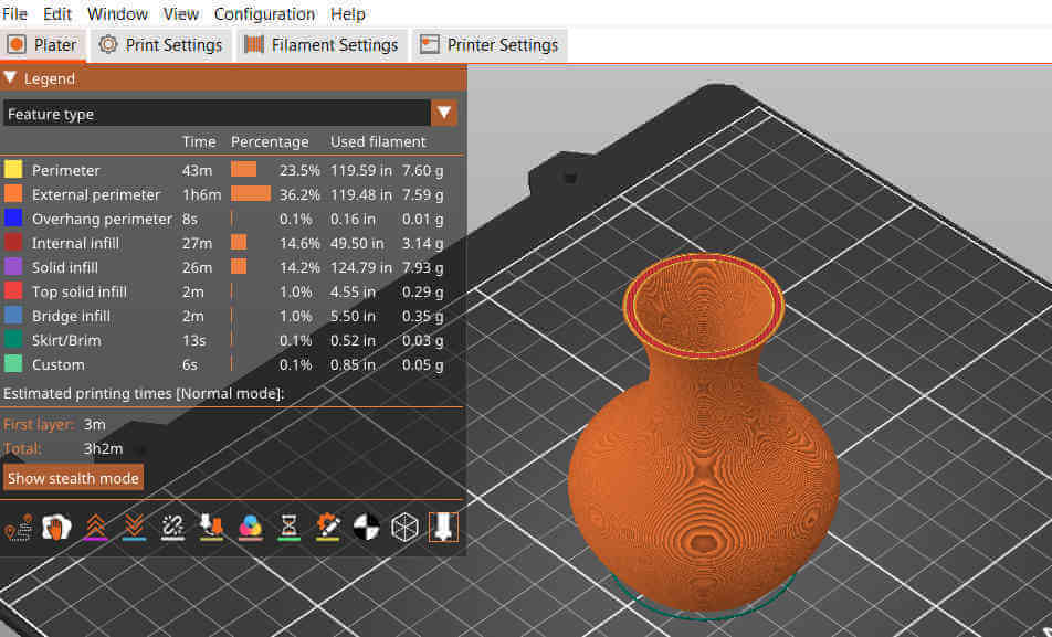
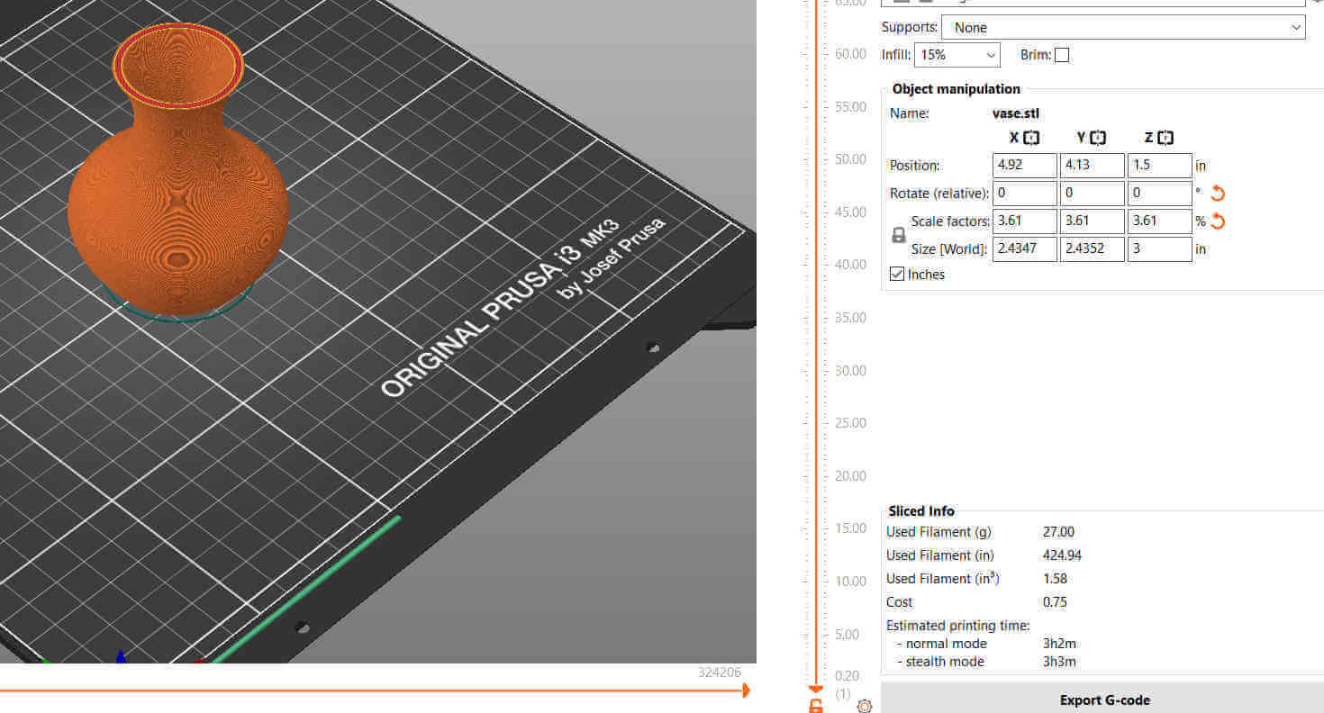
The object did not require supports because the curved angle was within a range that the machine can print easily, also becaause its a rounded shape, the layers can safely support the layer above next. I clicked on slice and this processed the settings making the object print ready. There were no errors found when sliced.
The file was exported as G-Code and was sent to the 3D printer via SD card.
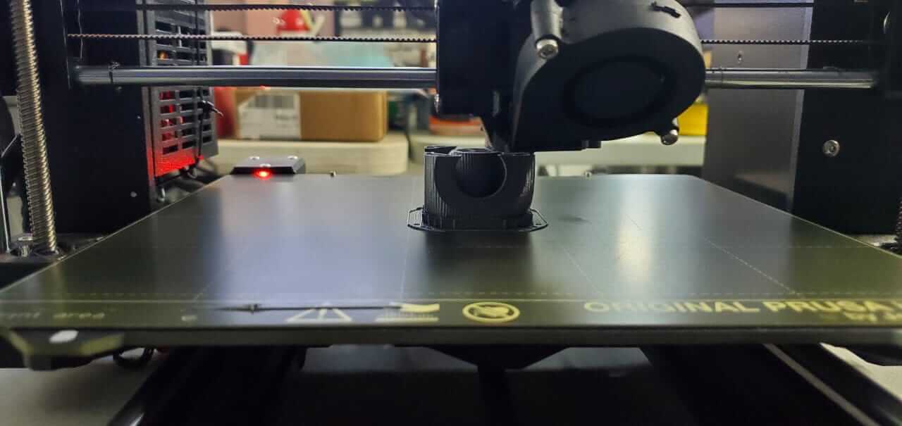
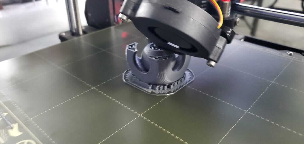
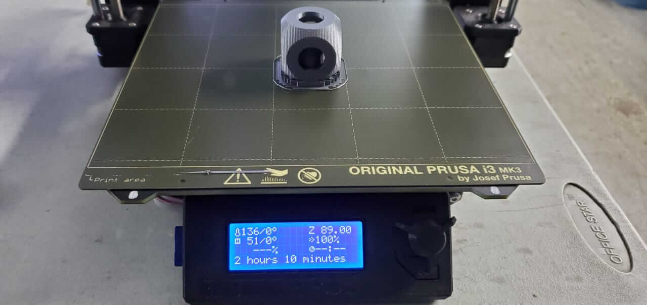
The file was loaded on the printer and was estimated 3 hrs. The extruder and bed was preheated to its required temperatures and printing began.
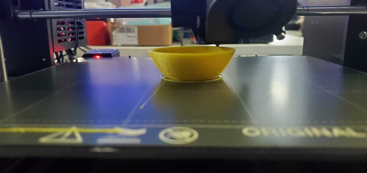
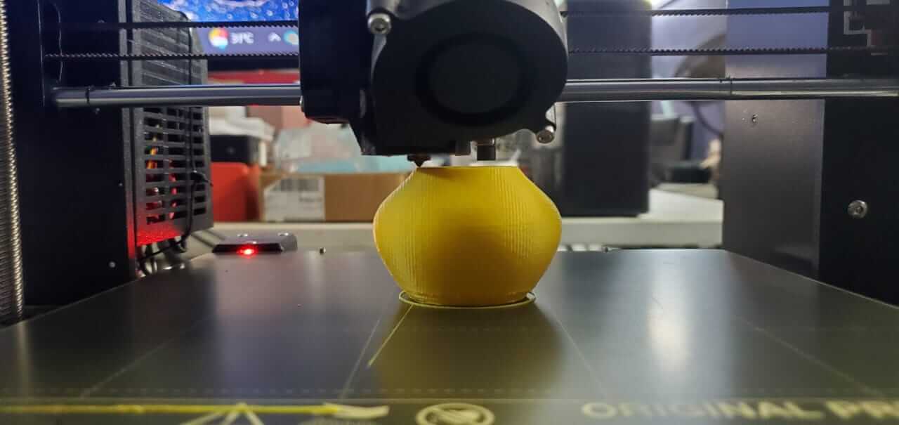
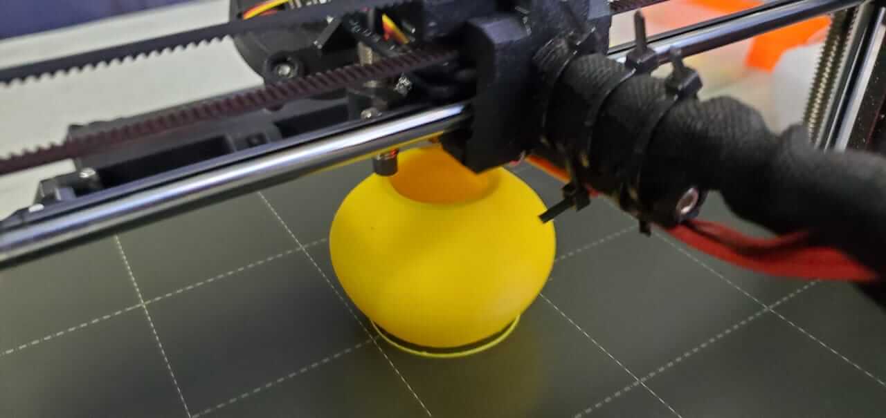
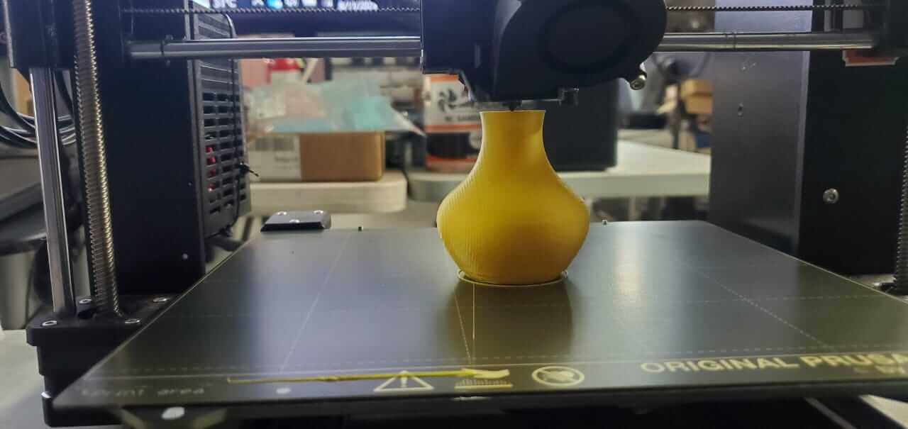
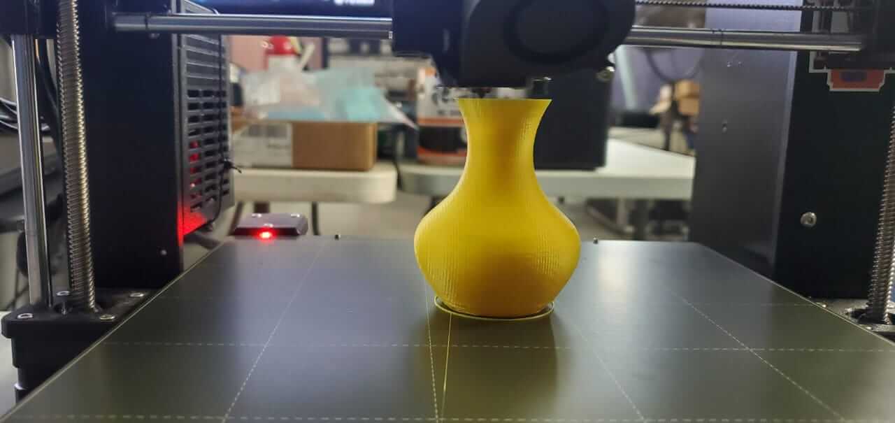
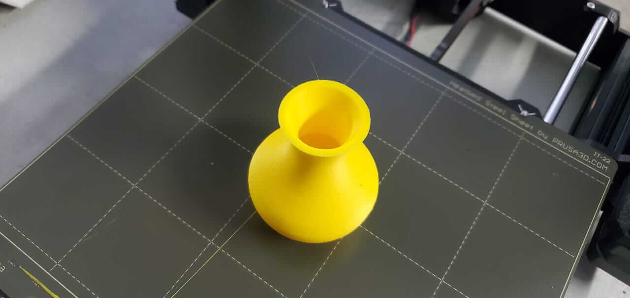
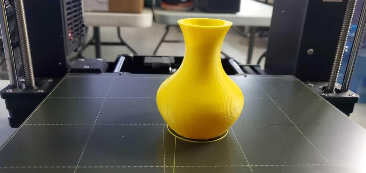
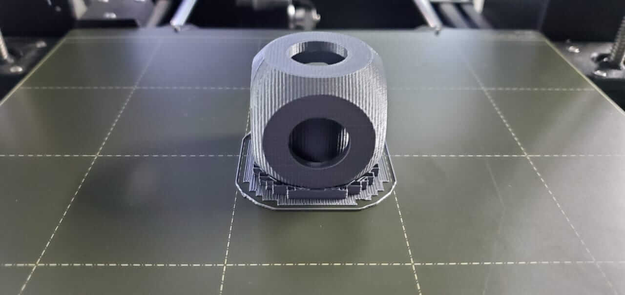
My completed 3D printed Vase.
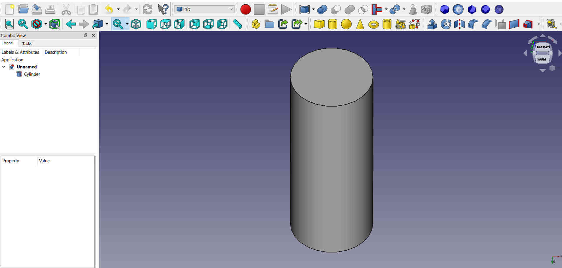
The vase came out pretty good so I wanted to print a cube fidget thingy. To do this I first selected the Part workspace. I then added a cylinder using the Create a cylinder tool.
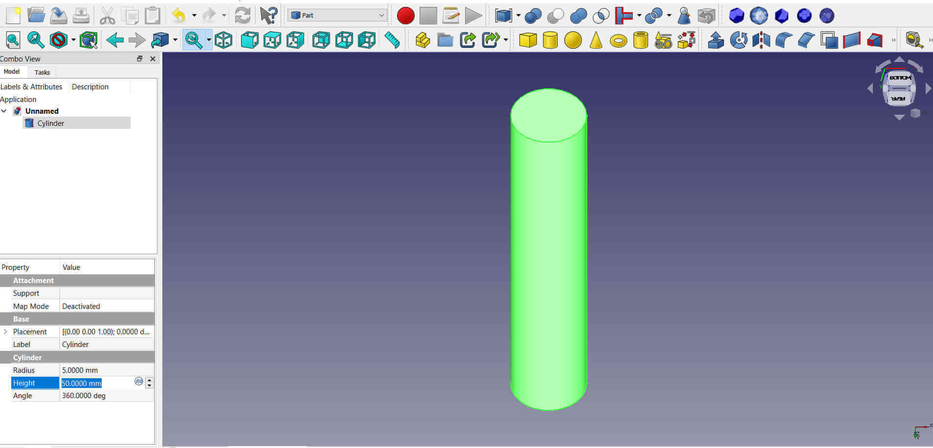
From the progress window I selected the cylinder object and its properties panel opened at the bottom left. I set the radius to 5mm and the height to 60mm.
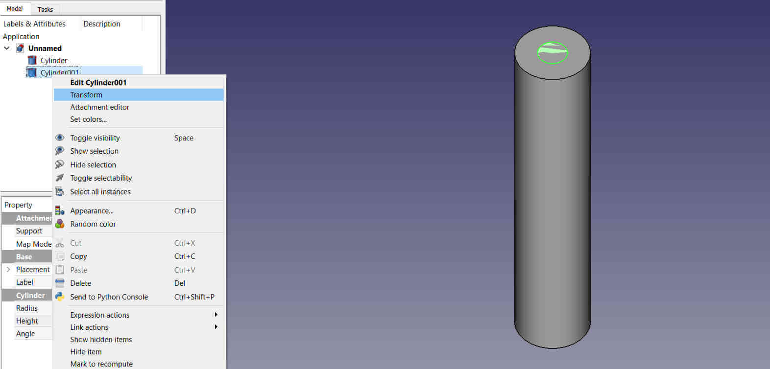
A second cylinder was added and given the same properties as the first. I right clicked on it from the progress window and selected Transform from its menu tab.
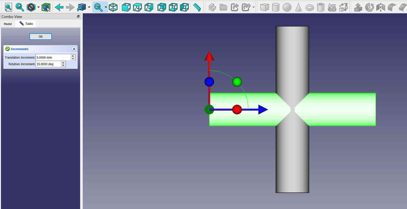
The Transform tool allowed me to rotate and position the part. I set the translation increment to 5mm and the rotation increment to 15 deg in order to easily position and center. I positioned the part so both parts form a plus sign.
I added a third cylinder and positioned it as seen in the image.
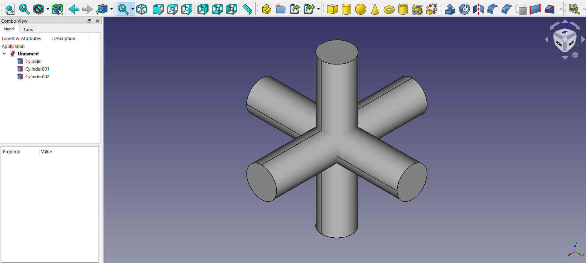
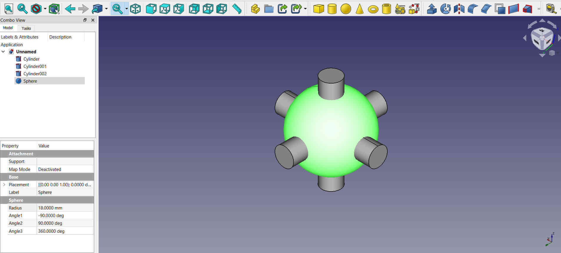
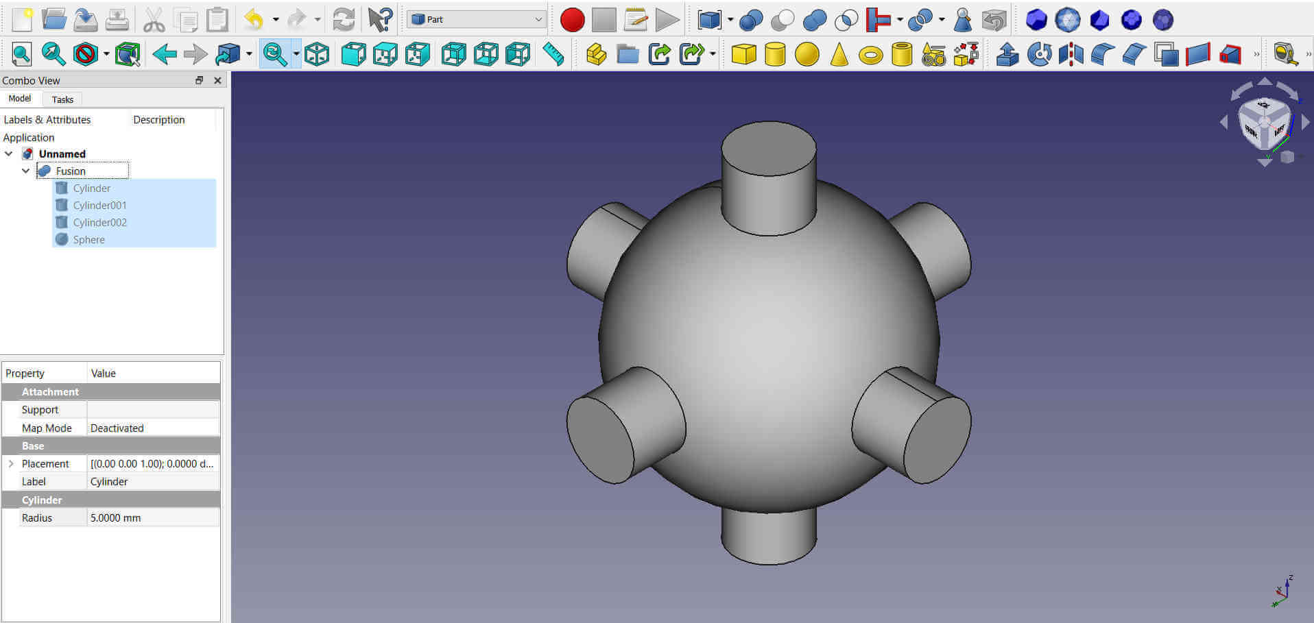
I then added a sphere using the Create a sphere solid tool. The radius was set to 18mm and the sphere was placed at the intersection of the cylinders.
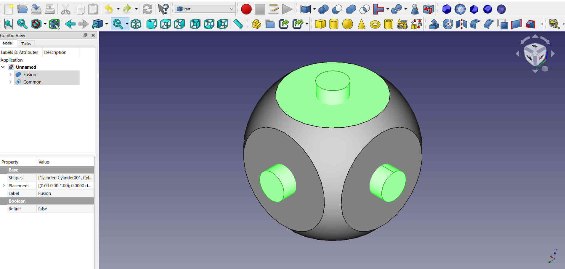
I needed to make 1 object from these 4 parts so I selected the 3 cylinders and the sphere and used the make a union from several shapes tool to fuse them together.
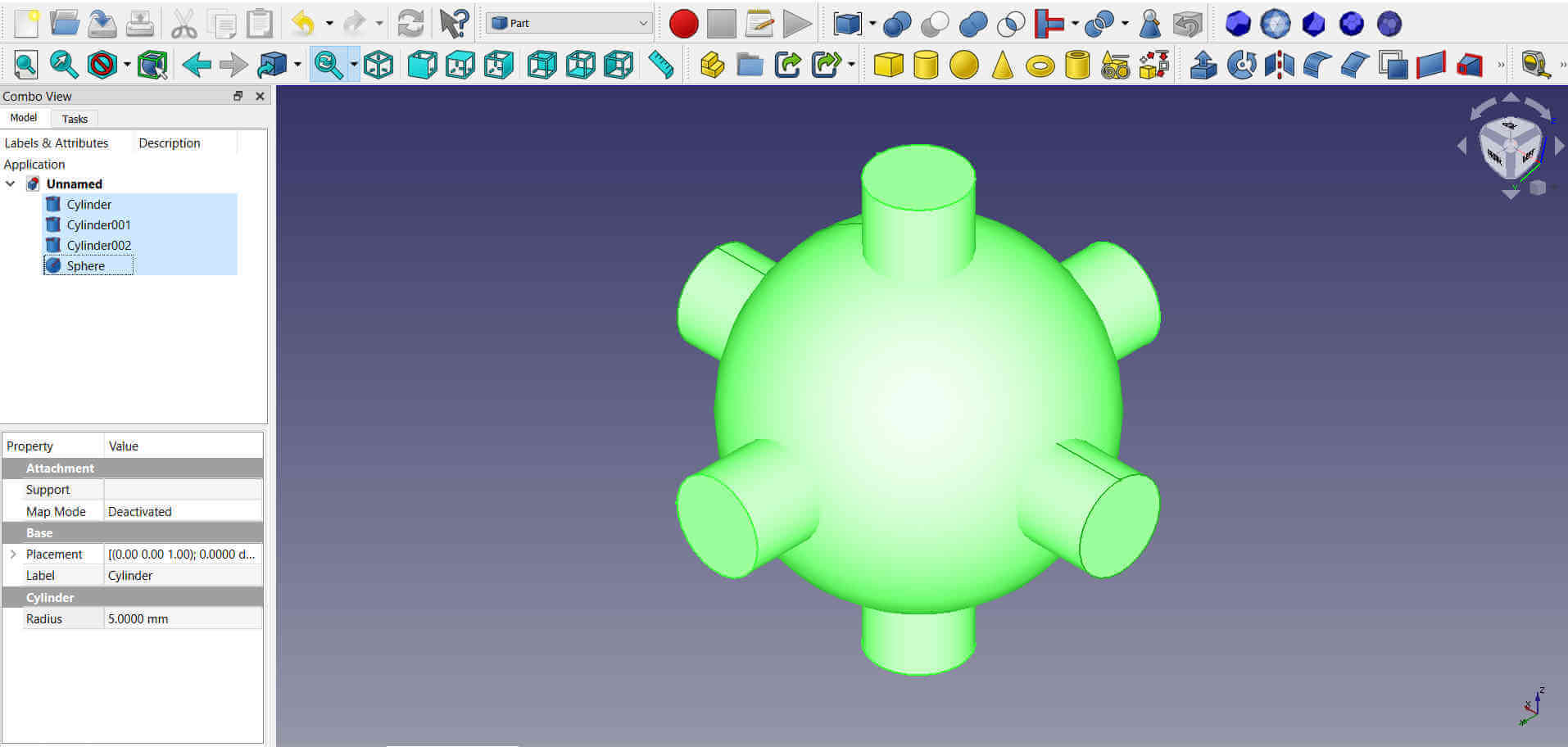
A new object appeared in the progress window named fusion. There was a drop down arrow next to it that allowed me to see all the individual objects that were fused togther. I can still edit the individual parts if necessary.
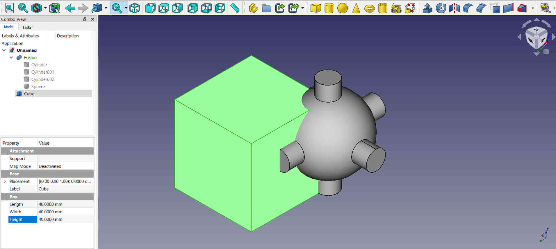
This fusion object was intended for the inside opened area of the final product. I added a cube using the Create a cube solid tool. The height, lenght and width were set to 40mm.
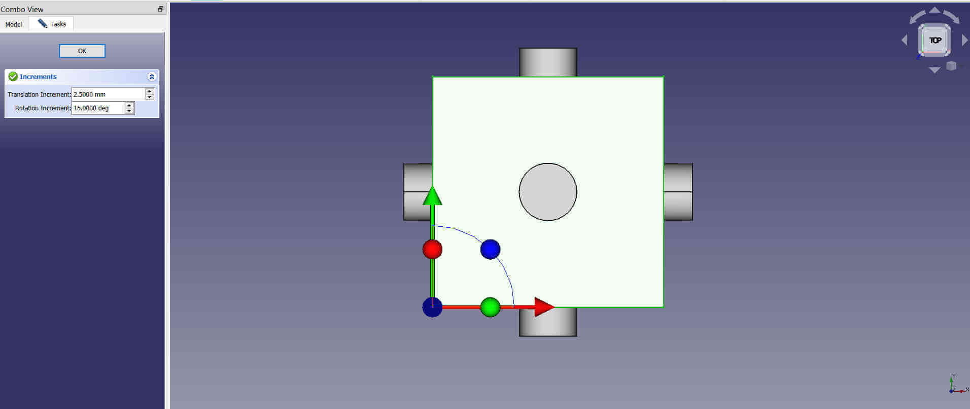
The cube was centered in the fusion object. I used a translation increment of 2.5mm to help center easily. Changing the view helped center it on all sides.
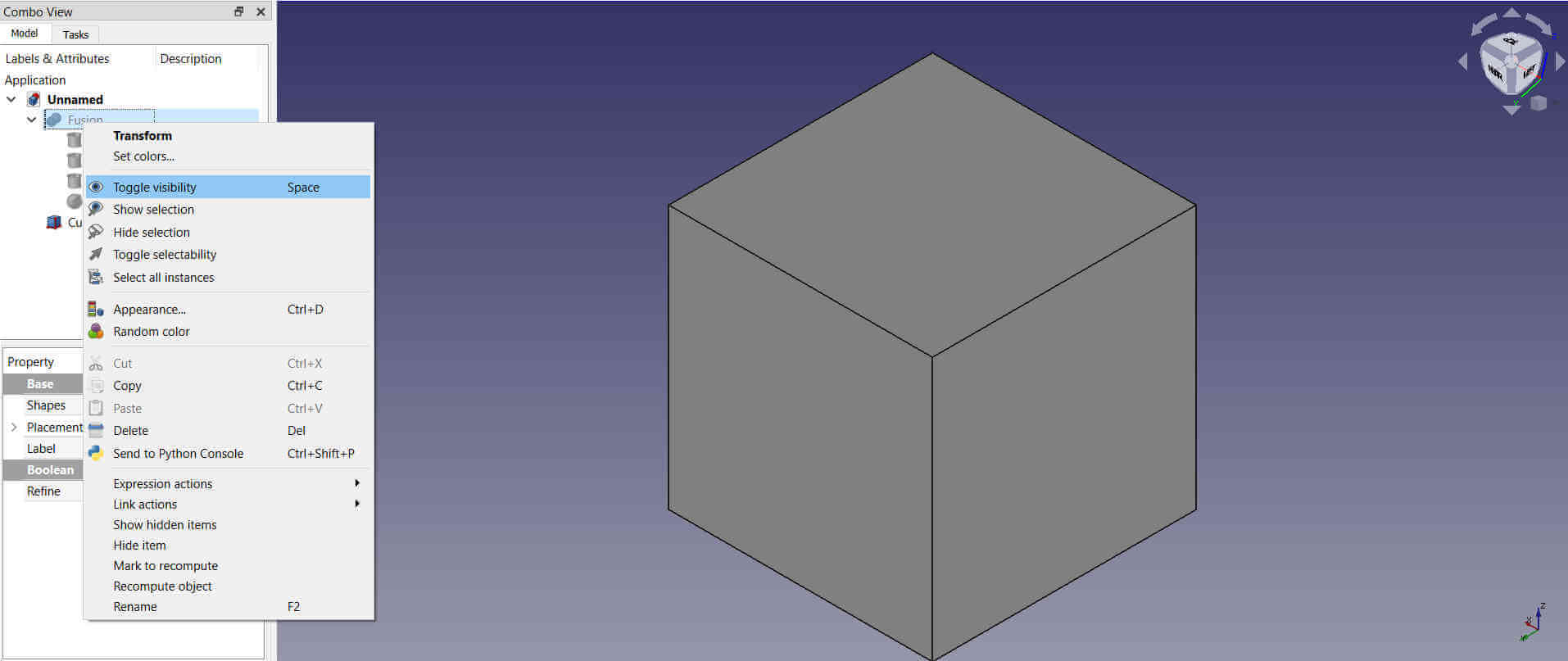
I needed to add another part but I wanted to temporarily hide the fusion object. To hide the object I right clicked on the fusion part in the progress window and clicked on toggle visibility from the menu. The part was now hidden.
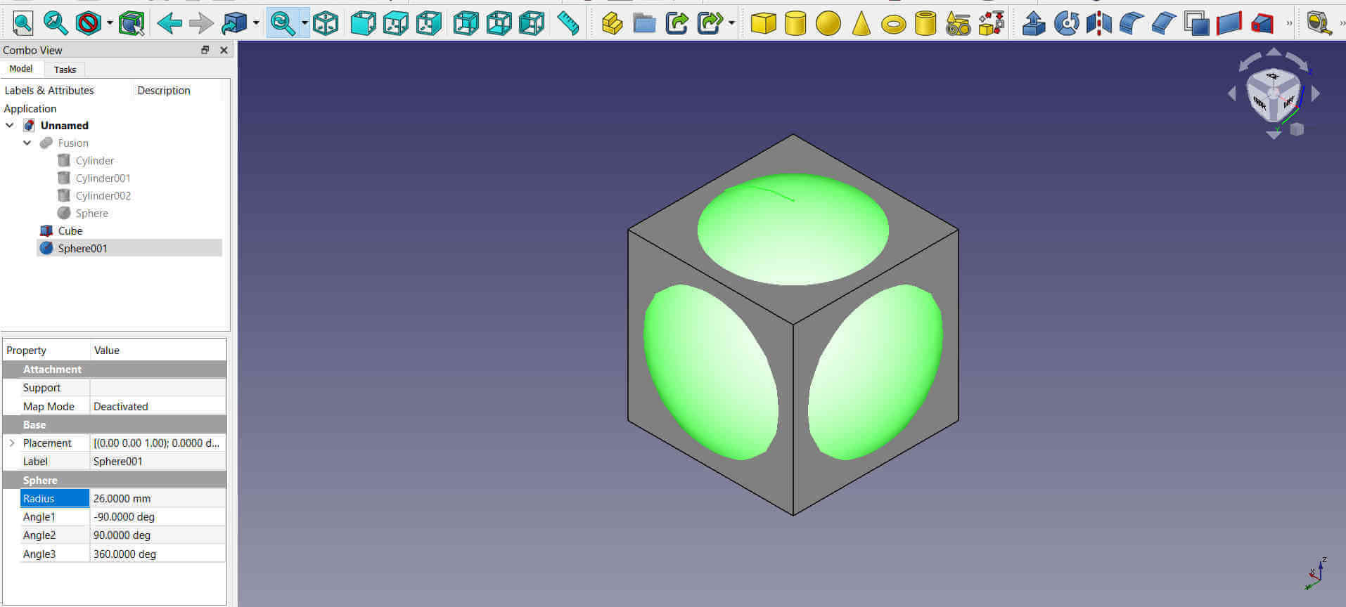
Another sphere was added center of the cube and given a radius of 26mm.
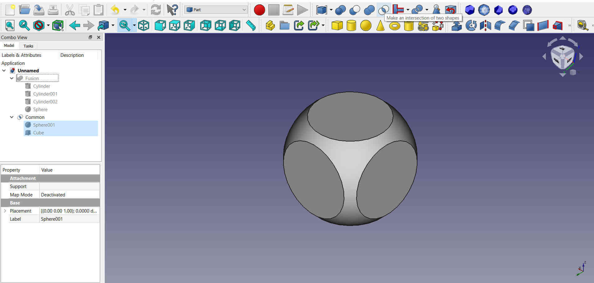
I wanted to get the cube with a rounded edge so I selected both the cube and sphere and I used the Make an intersection of two shapes tool to acomplish this. This tool removes all areas where both parts are not overlapping. A new common part was created inside the progress window.
The fusion part was made visible again.
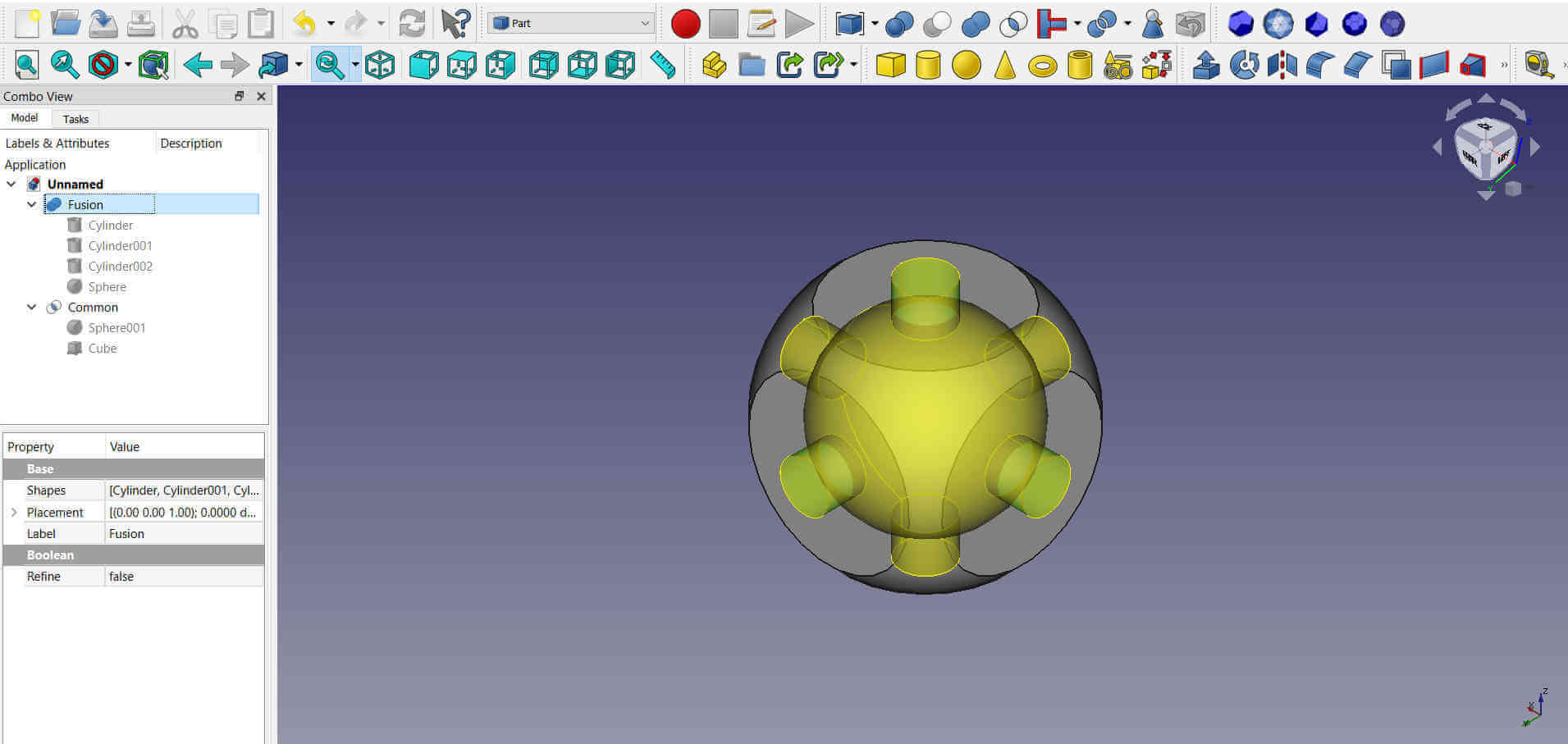
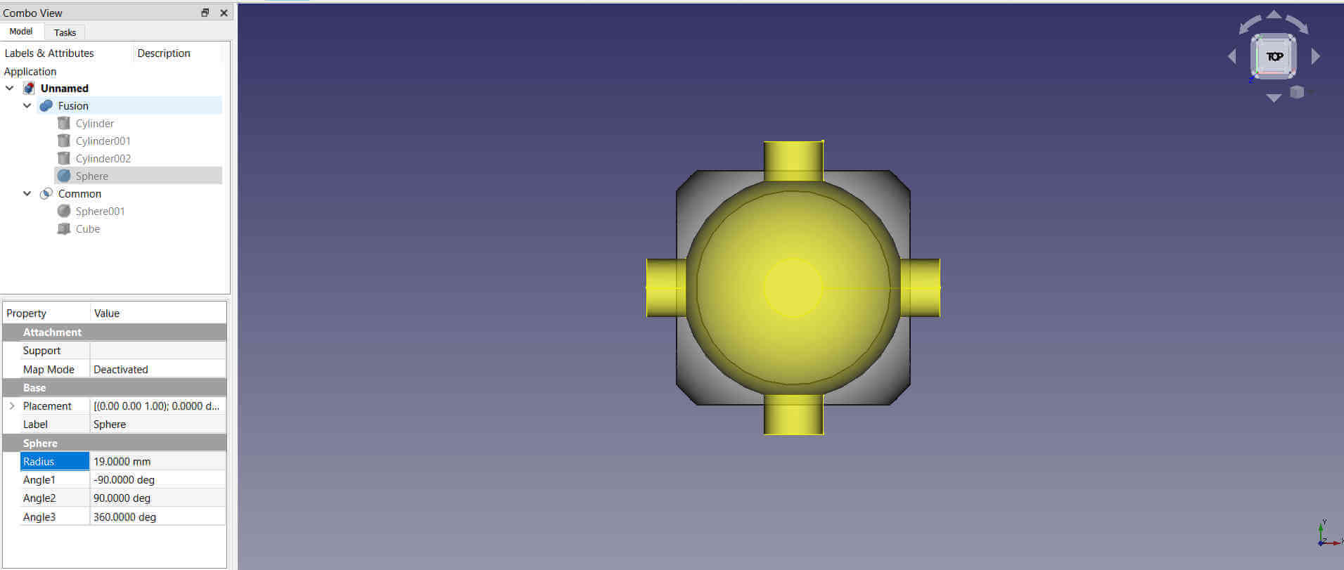
As I viewed the fusion part inside common part, I decided to make the sphere within the fusion part slightly bigger. The radius was increased to 19mm.
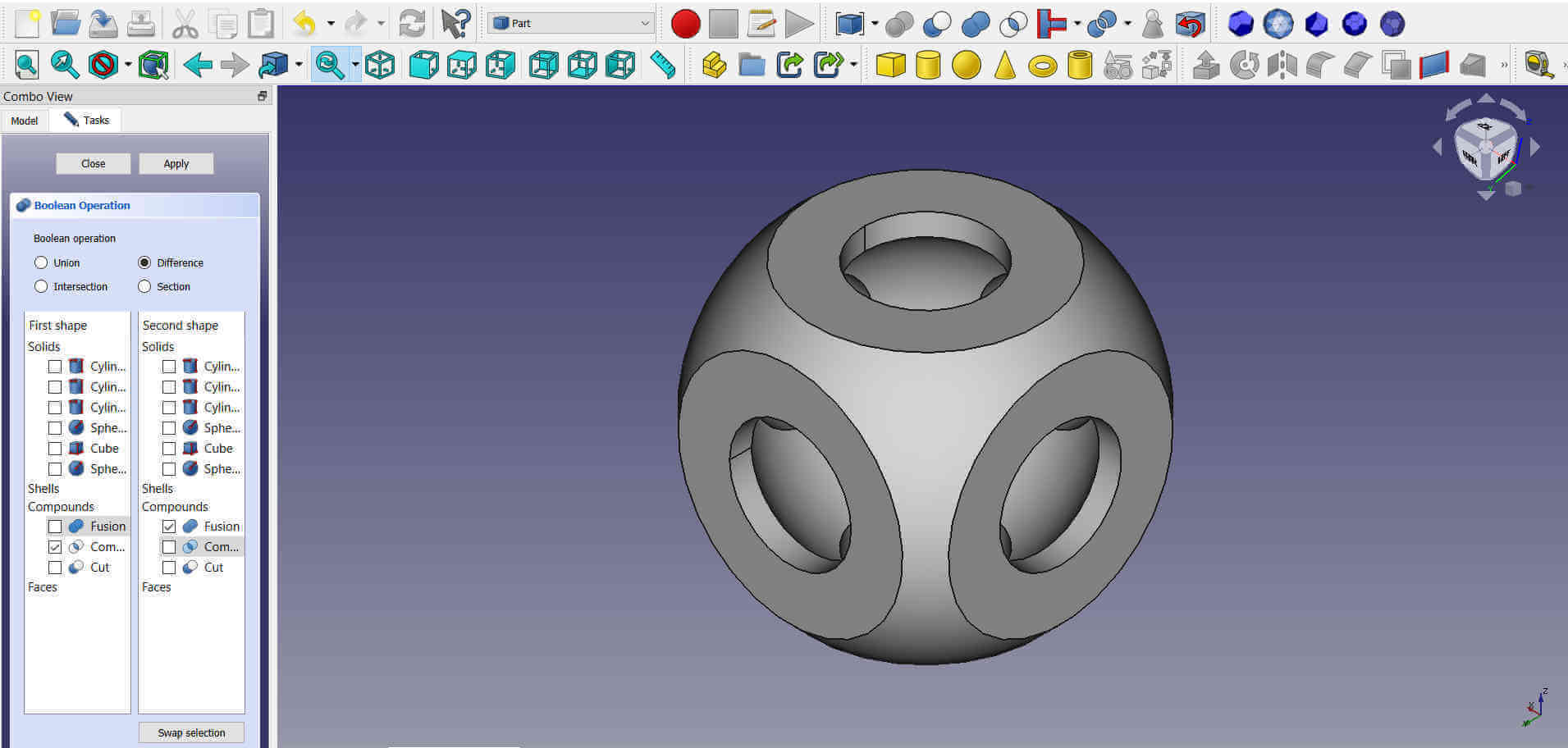
I needed to make a cut out inside of the rounded cube in the shape of the fusion part. To do this I had to use a booleon operation, so I first selected both parts.
I clicked the Run a booleon opertation with two shapes selected tool and a window opened with two sets of checkboxes. There was one side for First shape and another for Second shape. The first shape which is the common was the object I was taking away from and the second shape which is the fusion was the one I wanted to minus. I checked these objects and then I selected difference and then clicked apply.
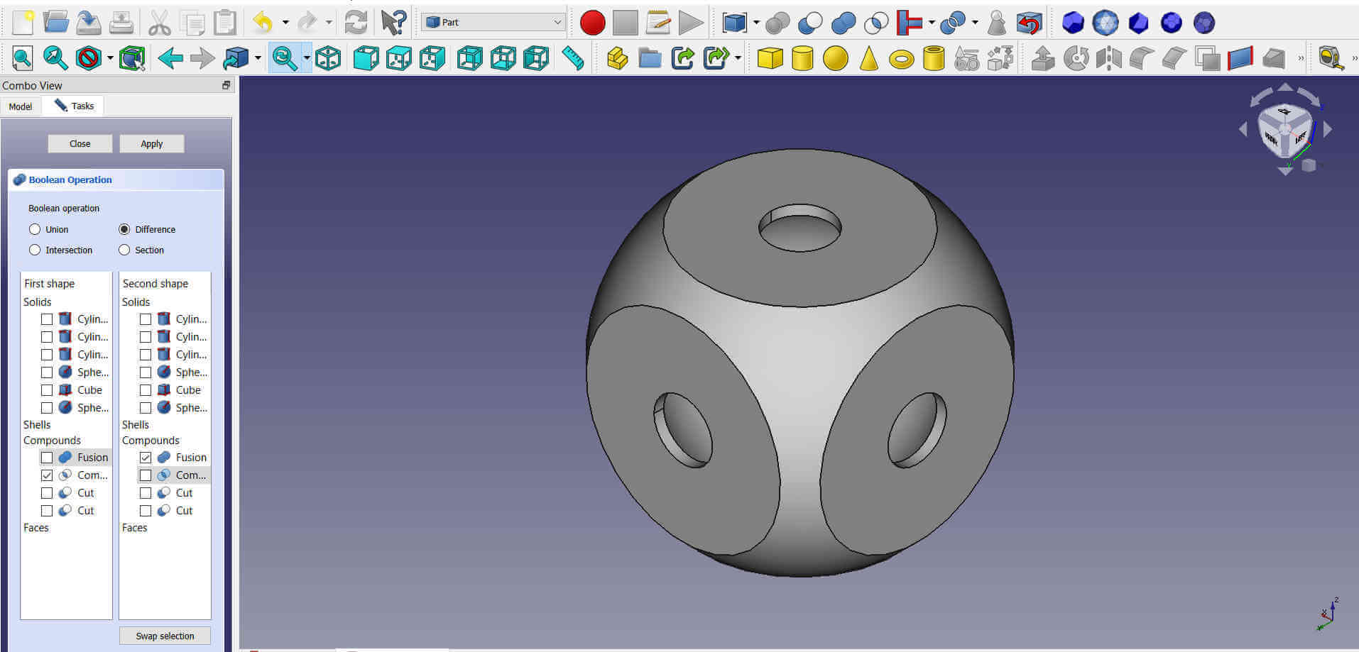
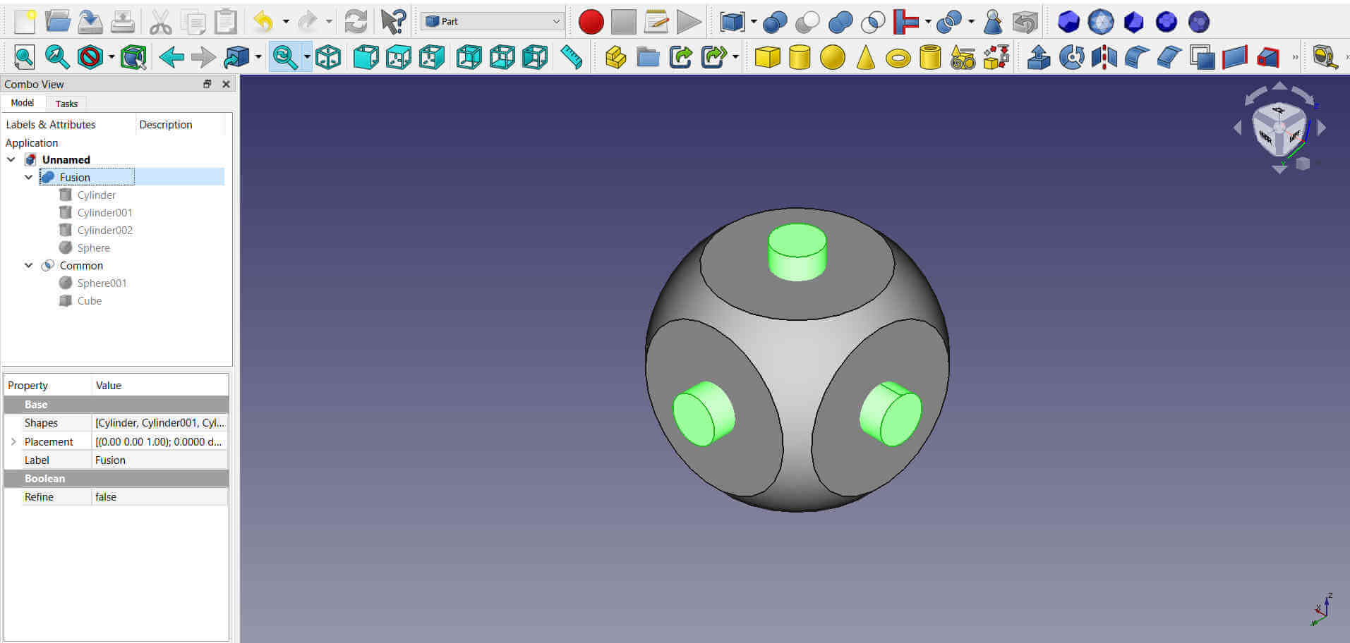
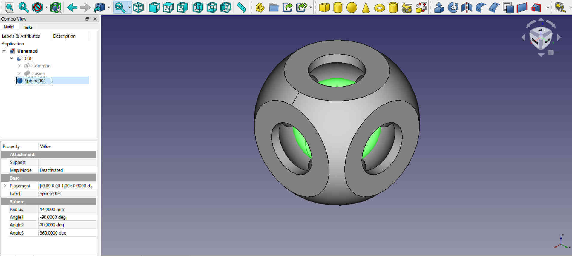
The operation worked, however I found that the holes were a bit small so I undid the operation and increased the fusion's cylinders radius to 9mm and ran the process again. A cut object was now seen in the progress window.
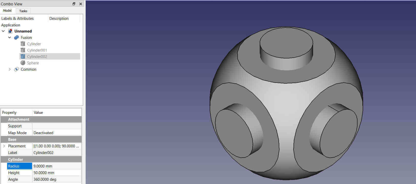
The holes were much better now.
Another sphere was added and placed at the center of the cube (cut). The radius was set at 14mm. This sphere needed to move about freely inside of the cube.
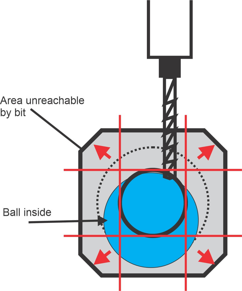
The following diagram shows areas that cannot be reached using a machine bit, therefore the fidget could not be made from a subtractive process.
The object was exported from FreeCAD as a .stl file and imported into Prusa slicer.

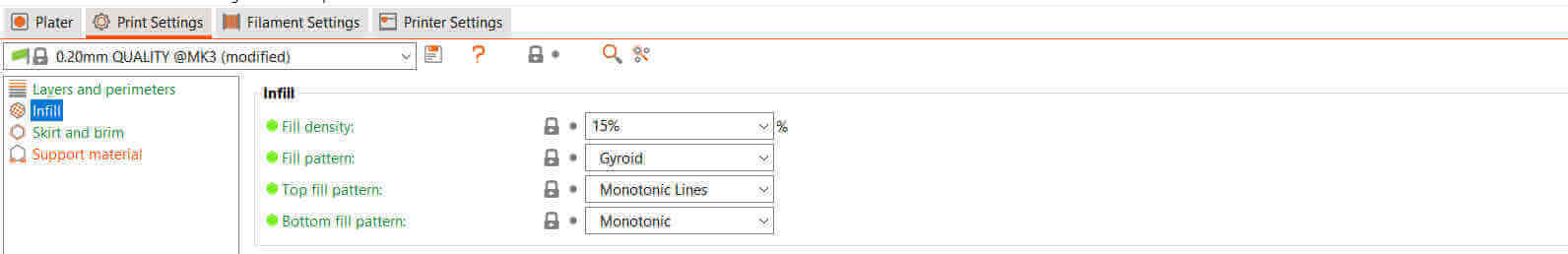
The layer height was set to 0.2mm from the print settings.
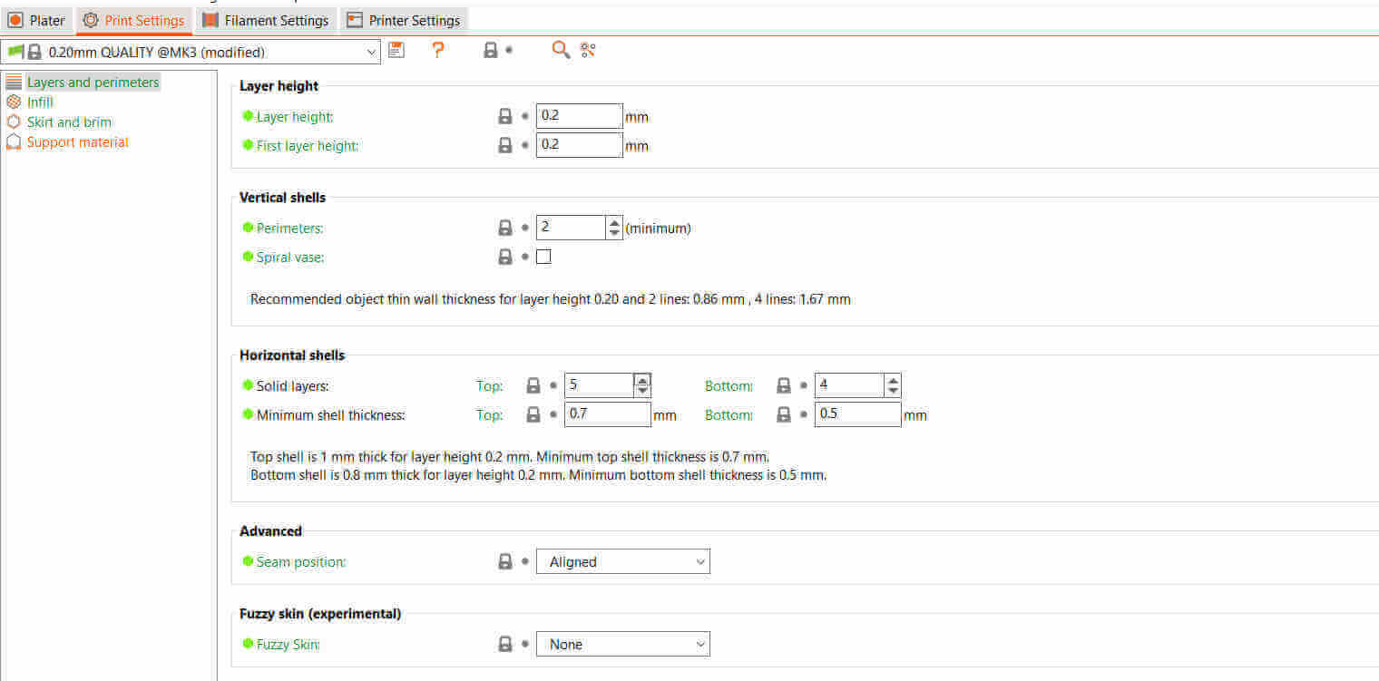
The infill was set at 15% else the sphere at the center would have been solid causing the print to take longer.
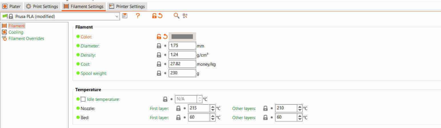
I decided to use PLA for this print. PLA is an acronym for Polylactic Acid which is a biodegradable plastic and can be used at lower temperatures than ABS. For this I selected the Prusa PLA from the list. The Nozzle temperature (extruder temperature) was set at 215 deg Celcius and the bed temperature at 60 deg Celcius.
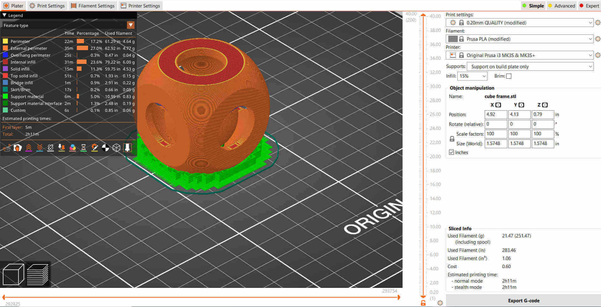
Supports were set to supports on build plate only which means supports will only be added under a floating part that is directly over the build plate. The object was then sliced with no errors and the G-code exported and sent to the printer via SD card.
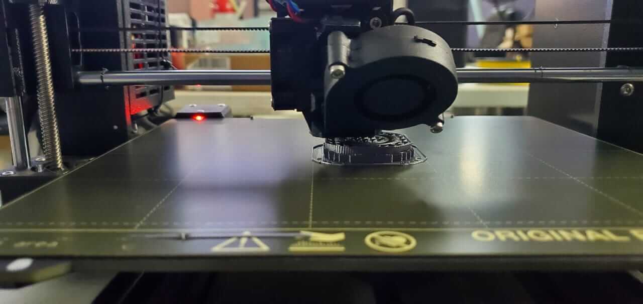
My cube fidget thingy was completed.
For this project I used a process called Photogrammetry. Photogrammetry is basically combining multiple 2D images to create a single 3D image. In this case I used my mobile phone to take photos of an object with the use of an app. I used Scann3D which is an app that assists you with taking proper photos and then merging them to create a 3D image.
First I had to figure out what I wanted to scan, so I decided I would do a Funko Pop "Thanos".

There were three main things I had to take into consideration which were :
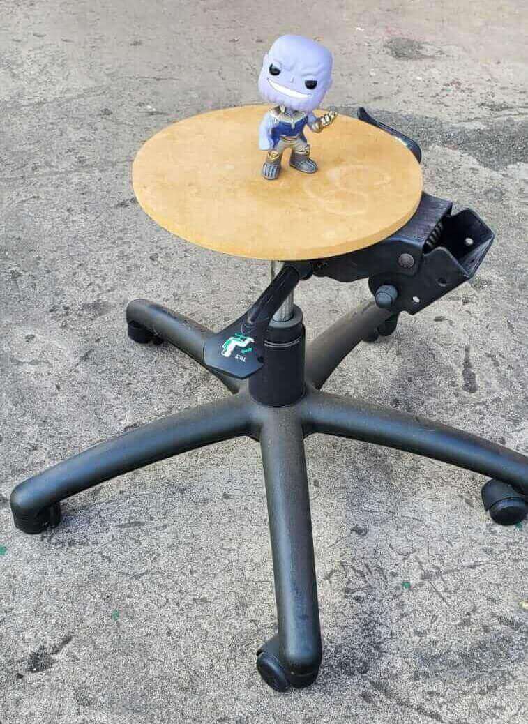
To attain proper lighting I did my scan outside. The background didn't work out too well on my first attempt since the camera kept including objects surrounding the model even though they were distant. To help this, I had my colleague hold a large cardboard sheet behind the model. I walked around the model taking the photos but when it was time to process, it failed because my distance from the model varied too much. I found a broken rotating chair outside the lab so I replaced the broken seat with a circle cut MDF. This made a make-shift rotating table to place the model on top. Normally the camera would move around the object but in this case it was vice versa.
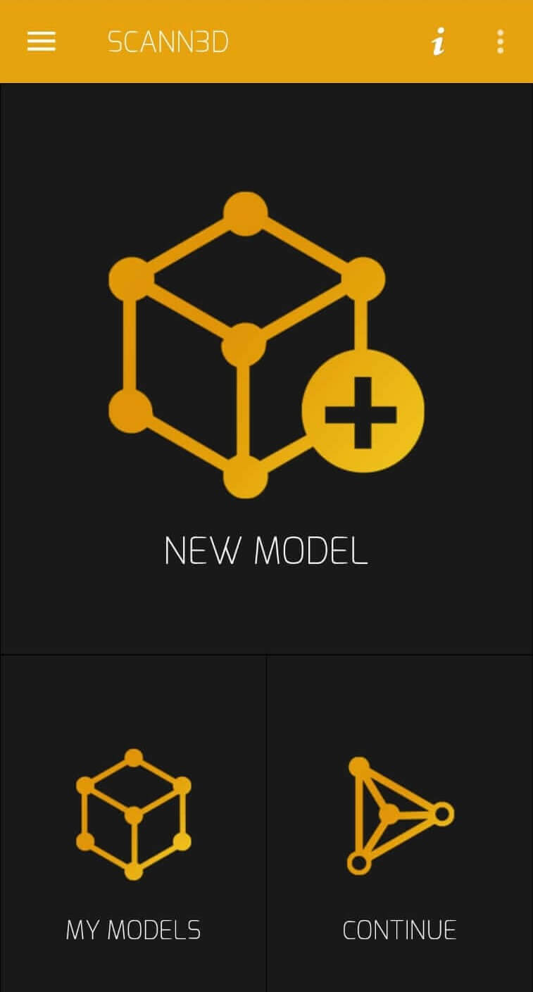
I opened the Scann3D and there were three options: New Model which starts a new scan, My Models to open folders containing previous scans and Continue to continue an unfinished scan.
I selected New Model to begin my scan.
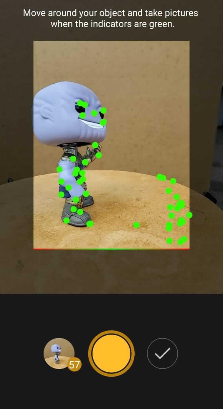
A camera opened with a bright yellow button to take a snapshot. I took the first photo and then rotated the table about 5 deg to 8 deg. For the second photo some guide dots appeared on the screen to assist with proper scan flow by guiding with good orientation of the phone. The dots surrounded the object that was in focus ( sometimes including parts of the table). When the dots were red, the orientation was way off so I needed to adjust both table an camera until dots were green or at least yellow.
Due to the phone's accelerometer and gyroscope, I still needed to twist the phone by a fraction of a degree in order to detect that the object model has been rotated. It worked well but it simply meant that it would have worked much better if I had the phone rotate around the model instead.
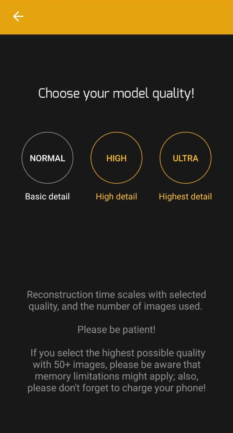
I took about 60 pics to get to a fair enough scan (the app recommends at least 20 photos to scan). I selected the tick next to the bright yellow snapshot button and this took me to a screen to select the model quality. There were three qualities: Normal for basic detail, High for high detail and Ultra for highest detail. I selected Normal because this would have processed faster since the other qualities would take much longer to result better quality. Also I am not sure my mobile phone would have had the sufficient specs to process higher qualities.
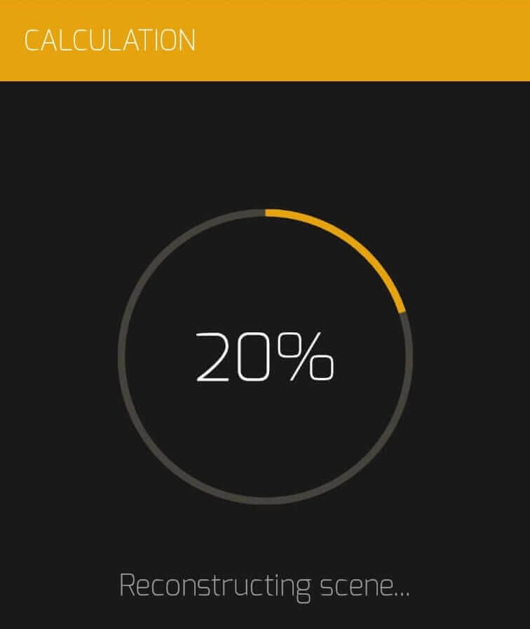
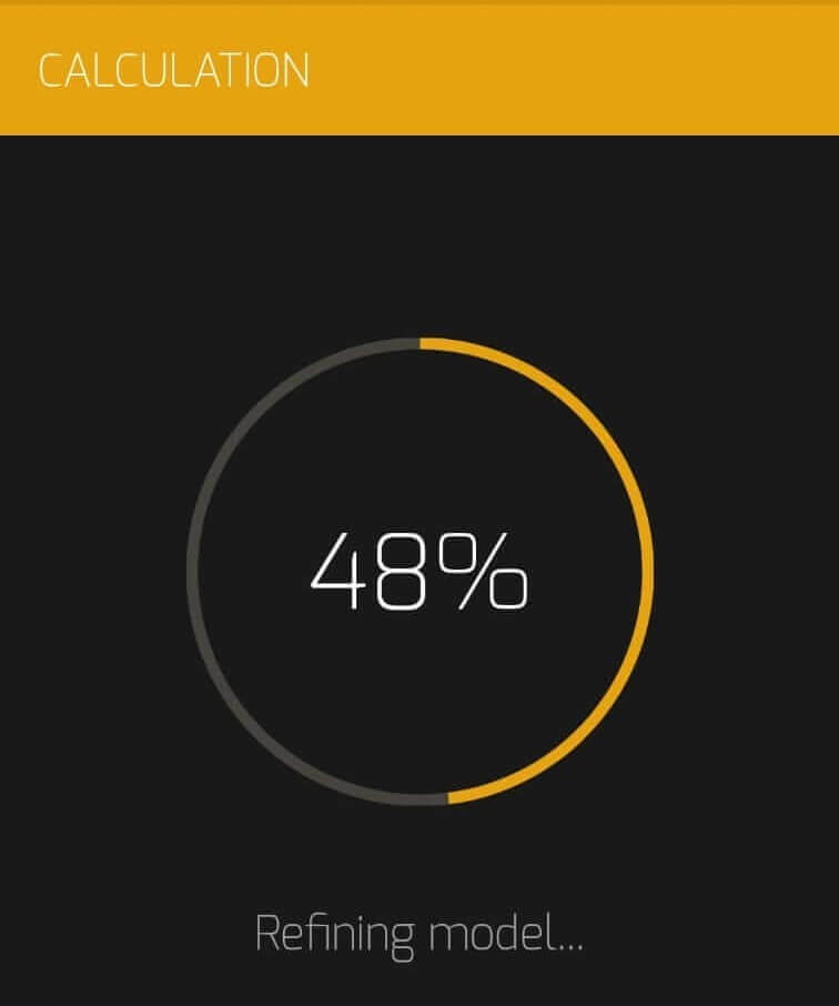
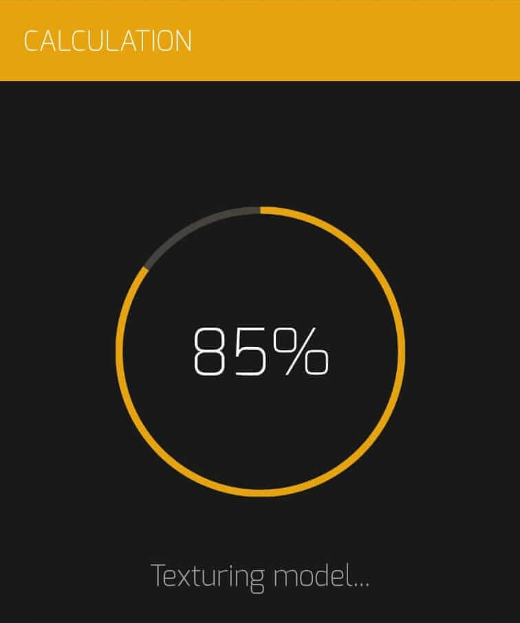
On selecting the quality, the app opened the Calculation page to process the images. This process included three stages: Reconstructing Scene, Refining Model and Texturing Model.
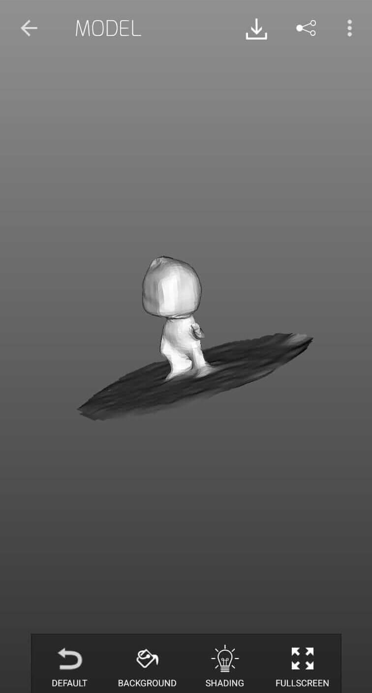
When the calculation was completed I pressed Open and was prompted to select either Legacy Viewer or Modern Viewer to veiw the model.

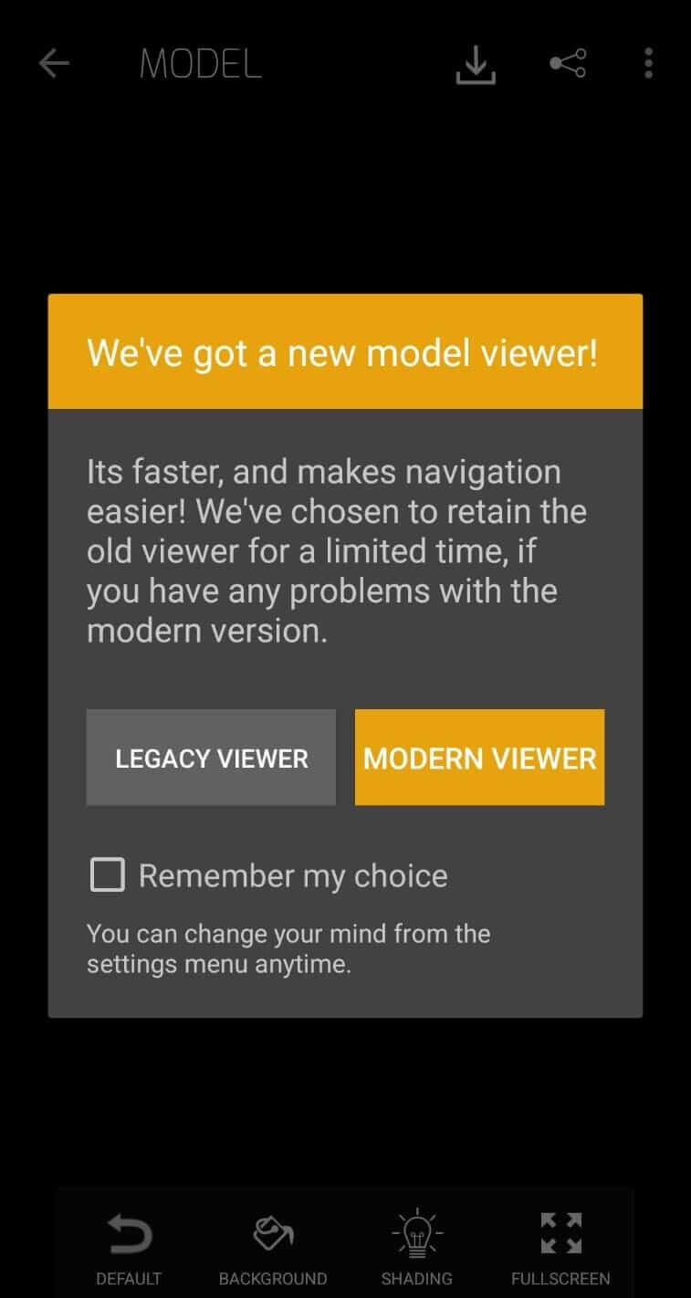
I selected the Modern Viewer. My scan processed pretty ok for a low quality scan and also with so little amount of photos. If I had taken more photos and used a higher quality I could have gotten a lot more details. I guess I will go that way when i need to 3D print> my scan>. The model was able to rotate view using my finger.
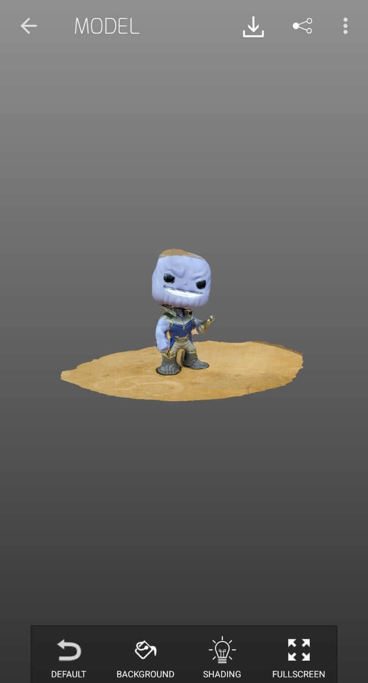
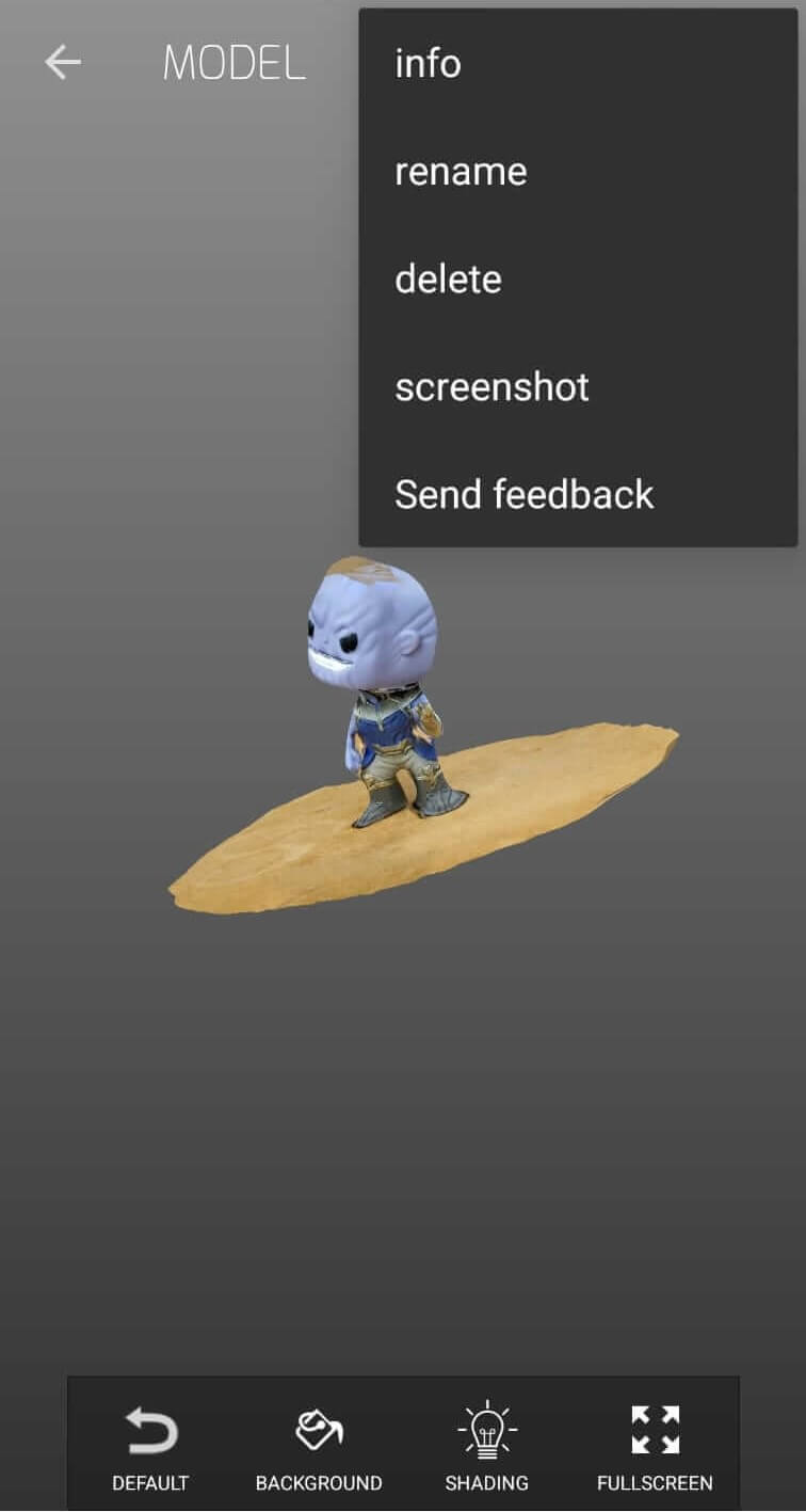
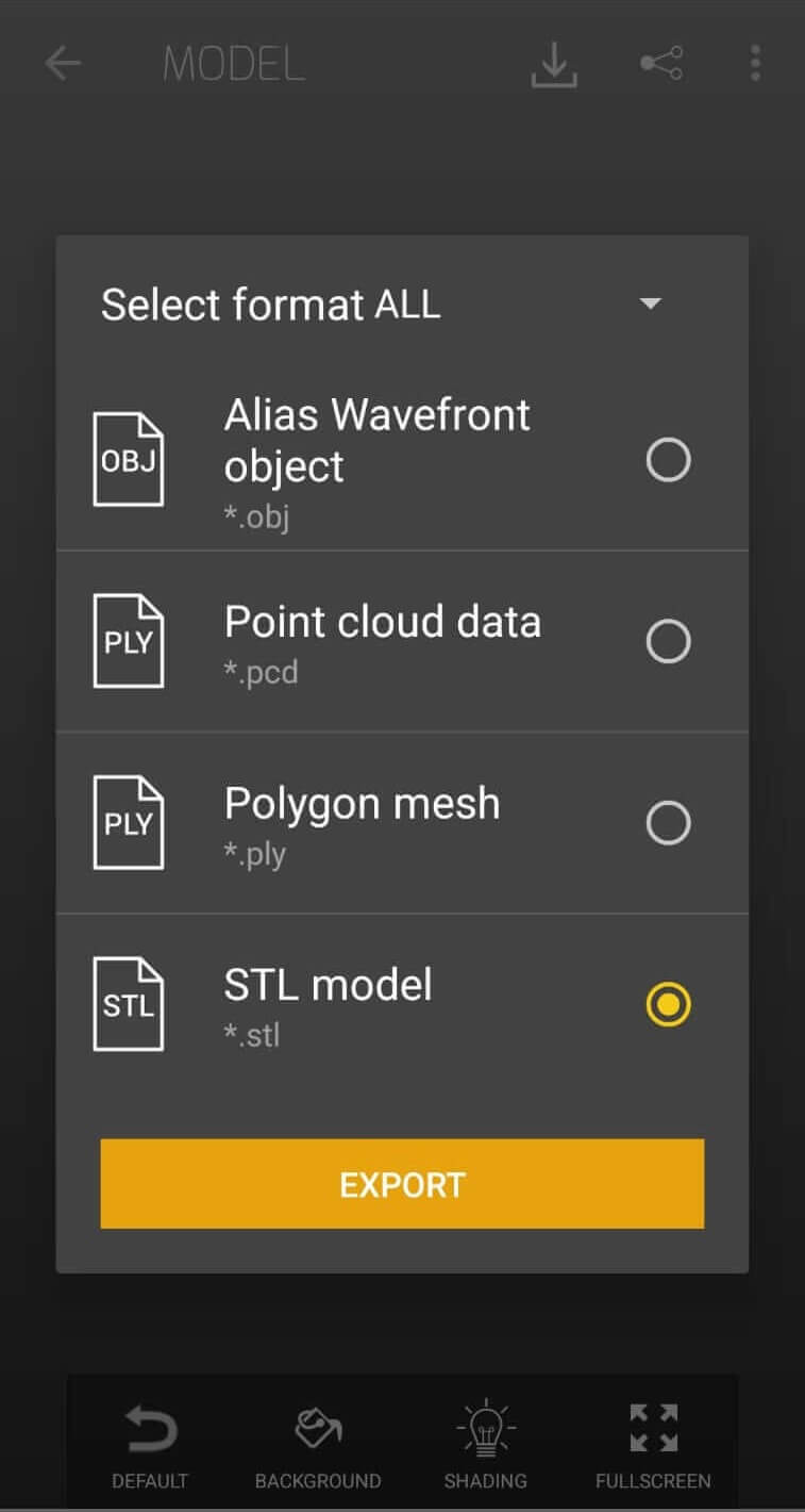
The Menu button (three dots at the top right) allowed me to view and customize the file details. The Download button (dowload icon at the top) allowed me to create and download a 3D printable file.
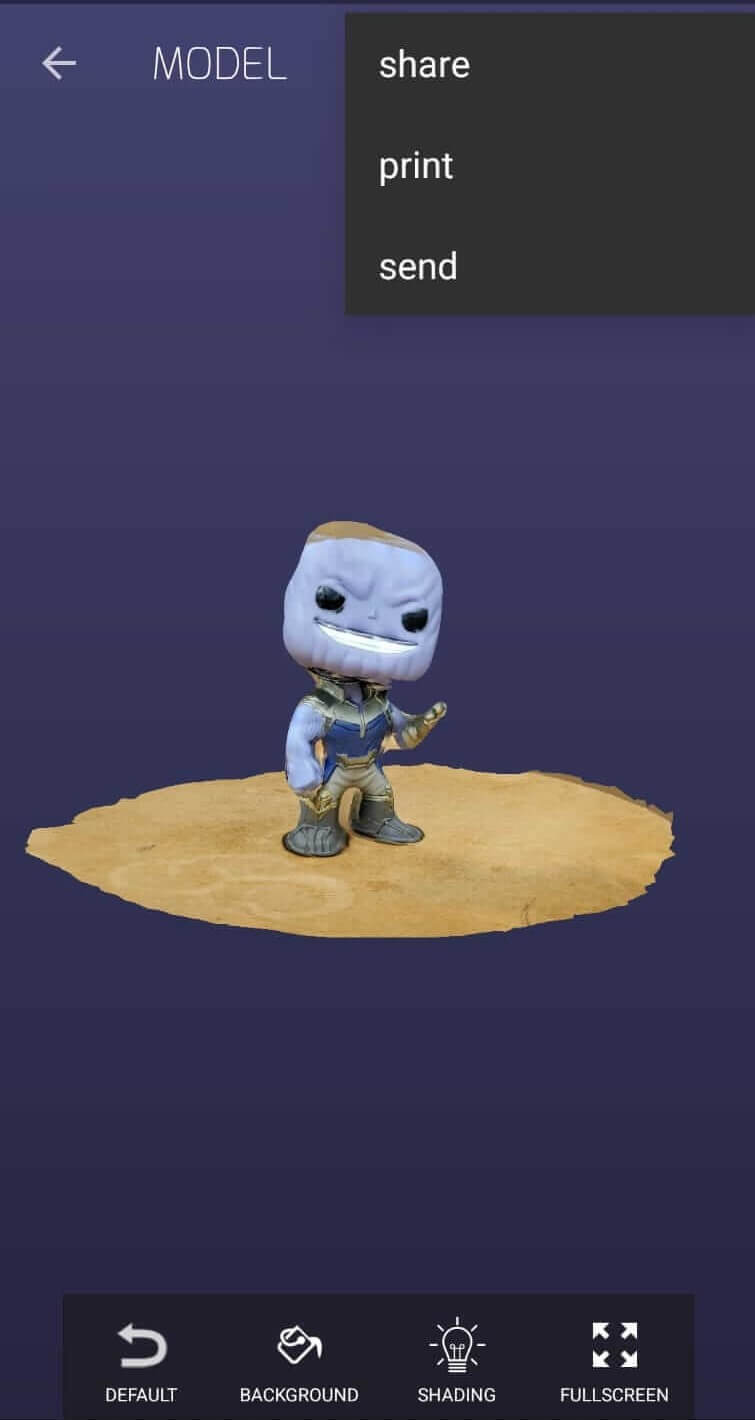
I selected print from the download menu and was allowed to select a 3D print file format to export. I checked .stl and pressed export but this brought me to a subscription screen. I guess I will subscribe if ever I need to print my scan.

Next time I will design a table where my camera can rotate and I will take more photos and use a higher processing quality to aquire a much better detailed scan.
For assistance with these projects I reviewed tutorials done by:
DIY Lab IIT Kharagpur
Joko Engineeringhelp