Characterize your lasercutter's focus, power, speed, rate, kerf, joint clearance and types.
Link to Group Assignment Cut something on the vinylcutter.
Design, lasercut, and document a parametric construction kit,
accounting for the lasercutter kerf,
which can be assembled in multiple ways,
and for extra credit include elements that aren't flat.
Assignment Requirement
Status
Linked to the group assignment page.
Completed
Explained how you created your parametric design.
Completed
Documented how you made your press-fit kit.
Completed
Documented how you made something with the vinyl cutter.
Completed
Included your original design files.
Completed
Included hero shots of your results.
Completed
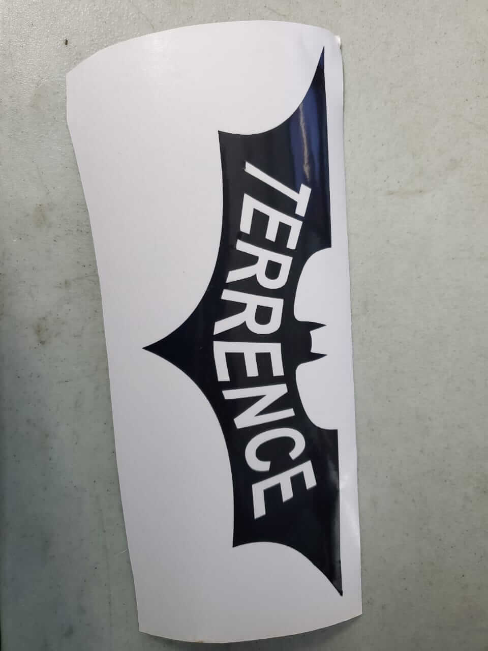
The first part of this assignment I decided to cut the dark knight logo with my name inside (and yes, I am a huge Batman fan).
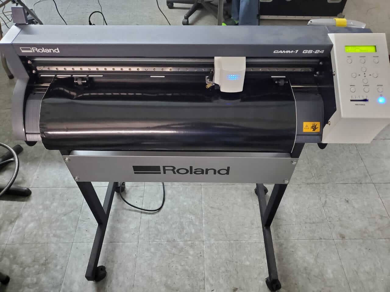
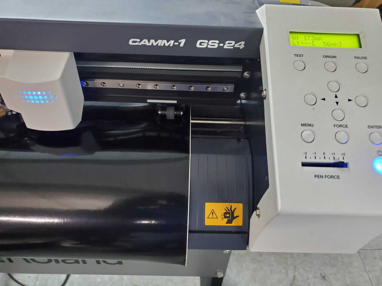
I used the Roland gs-24 vinyl cutter to cut my design.
I downloaded an image of the dark knight logo
which I traced and customised using CorelDraw.
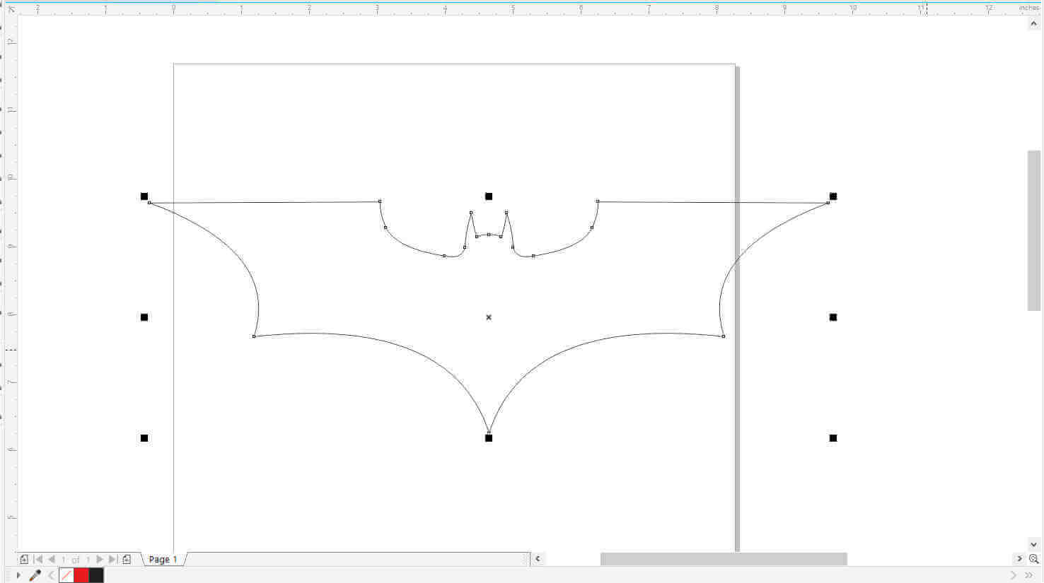
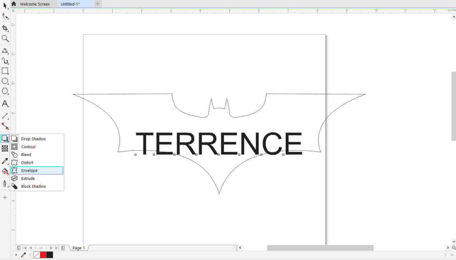
I first imported the image into CorelDraw and traced the outline using the 3-point line tool.
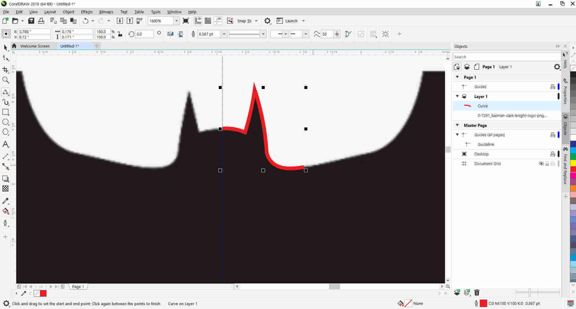
I deleted the original image where I remained with just the outline created.
I inserted text with my name and I used the envelope tool to bend and change the shape of my name to match the batman image outline.
This took a bit of playing around to get the right shape.
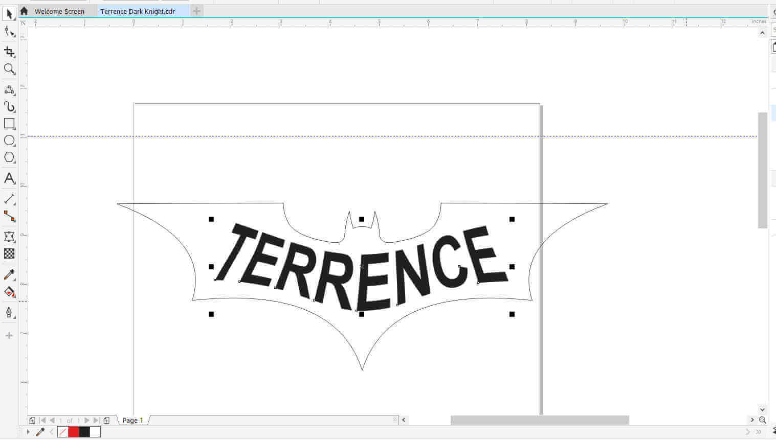
To complete the image I filled the outline trace black and the text white. The image was then exported as a bitmap image (.bmp).
.

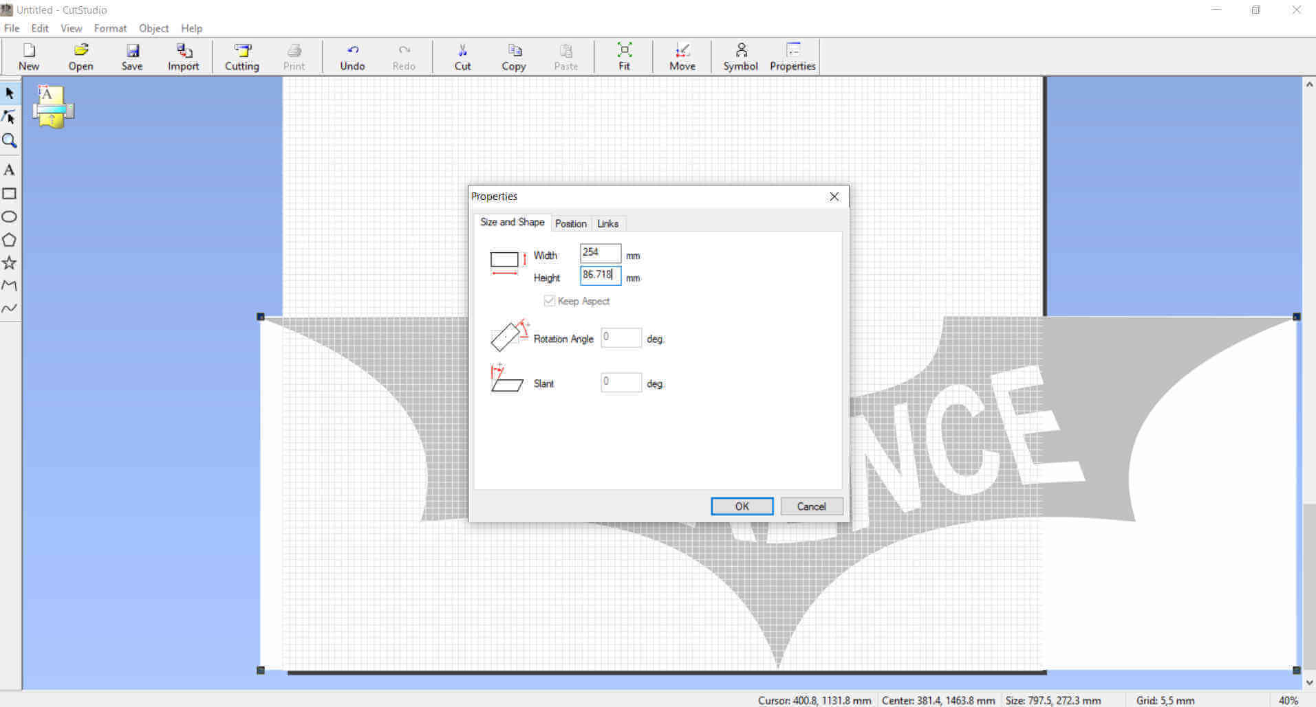
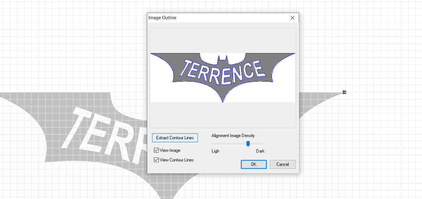
I imported the image into Roland Cut Studio (This is the default design software with drivers for the Roland Vinyl Cutter). I resized the image to 250mm (10 inches) width.
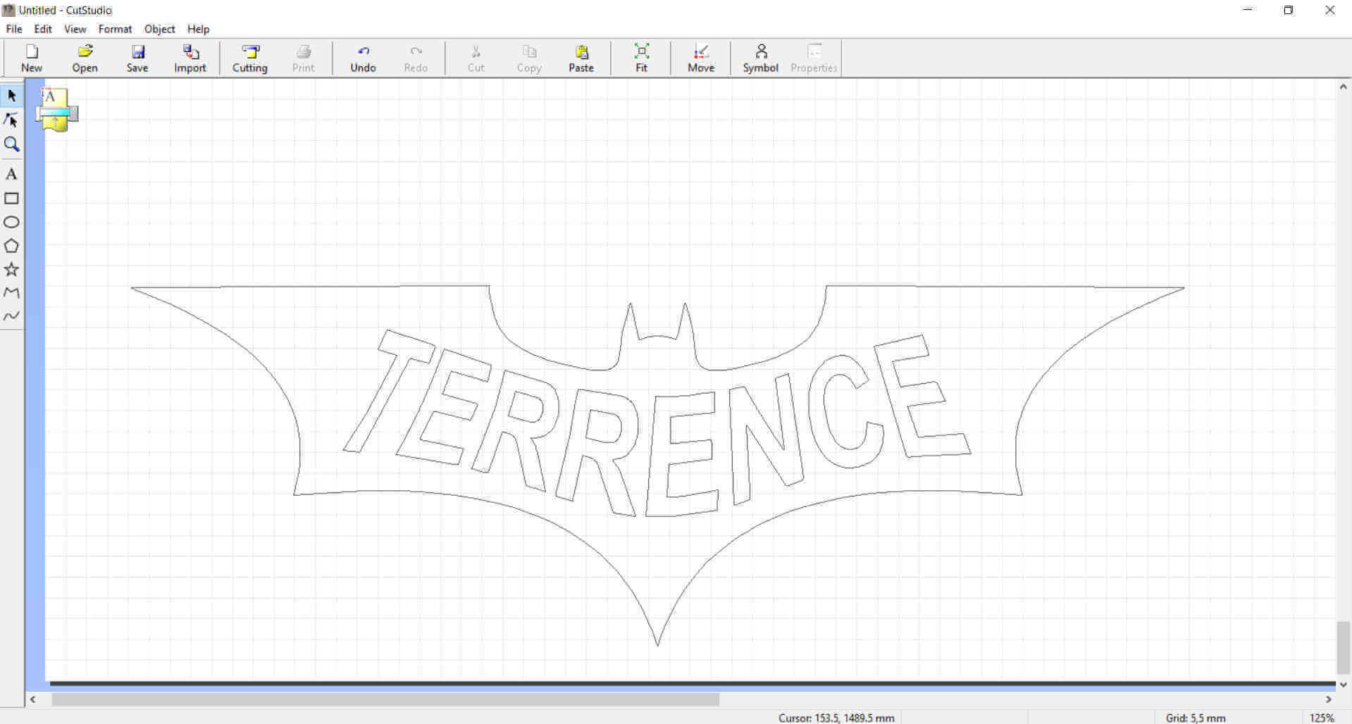
I selected the image outline tool from the objects menu tab and extracted the contour lines. The contour lines are the outline areas that will be recognised as cut paths by the machine.
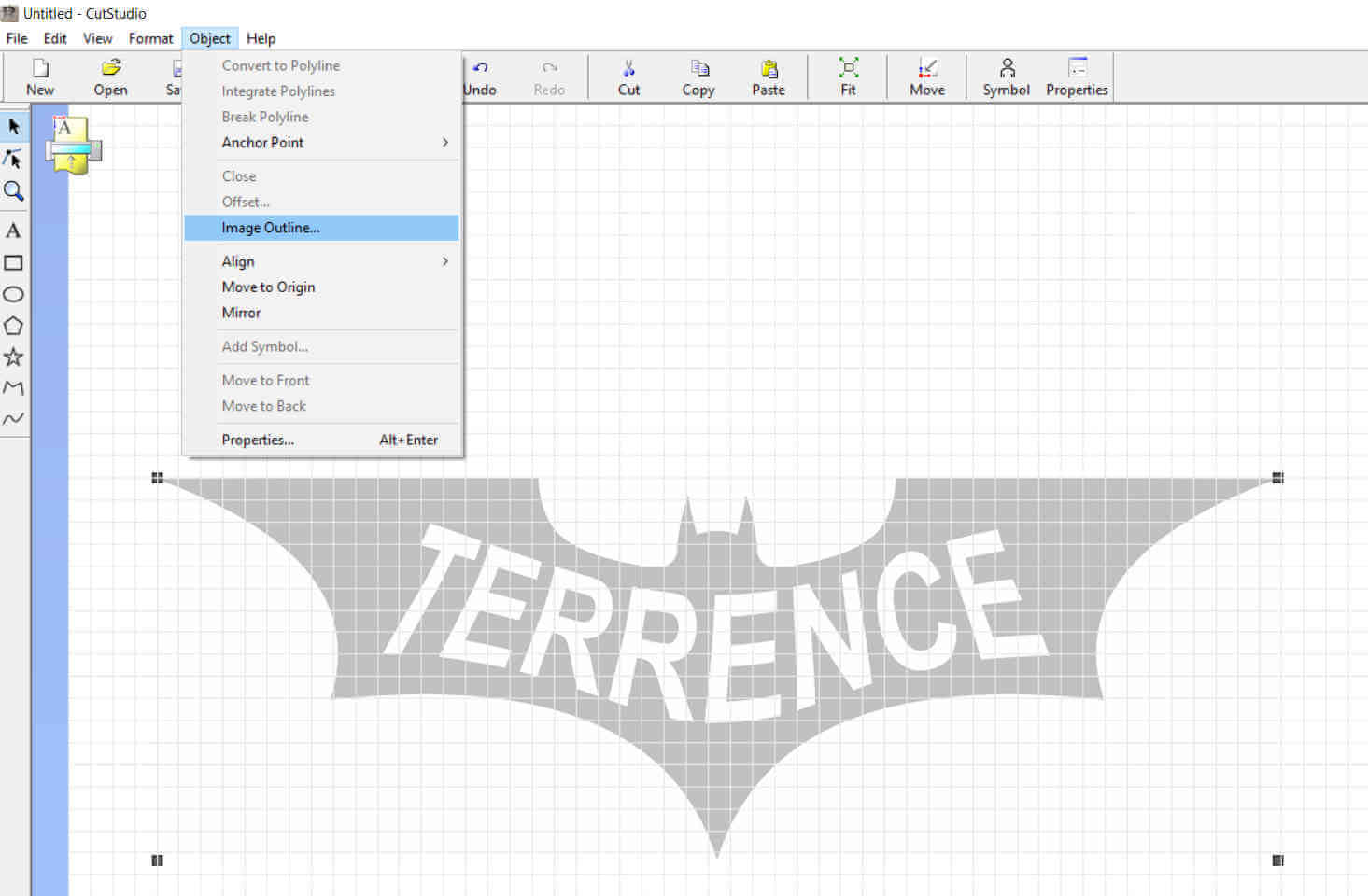
The alignment image density selector adjusts the flow of the contour line with respect to the original image outline, basically varying the smoothness of the line. This helps if the original image is low quality and edges are jagged or pixilated, I can use to make the contour lines smooth in those areas.
I loaded the vinyl cutter with black vinyl and adjusted the rollers to compensate for the width of the vinyl. Along the track there are sensors
to sense when the vinyl is loaded. If no vinyl is loaded the michine will not run the job.
The vinyl I used had a bad edge making it a bit uneven at certain spots, so I had to align the image where it will be cut on spot with the least
waves and I adjusted the pen force to 1.5 in order to get a clean cut.
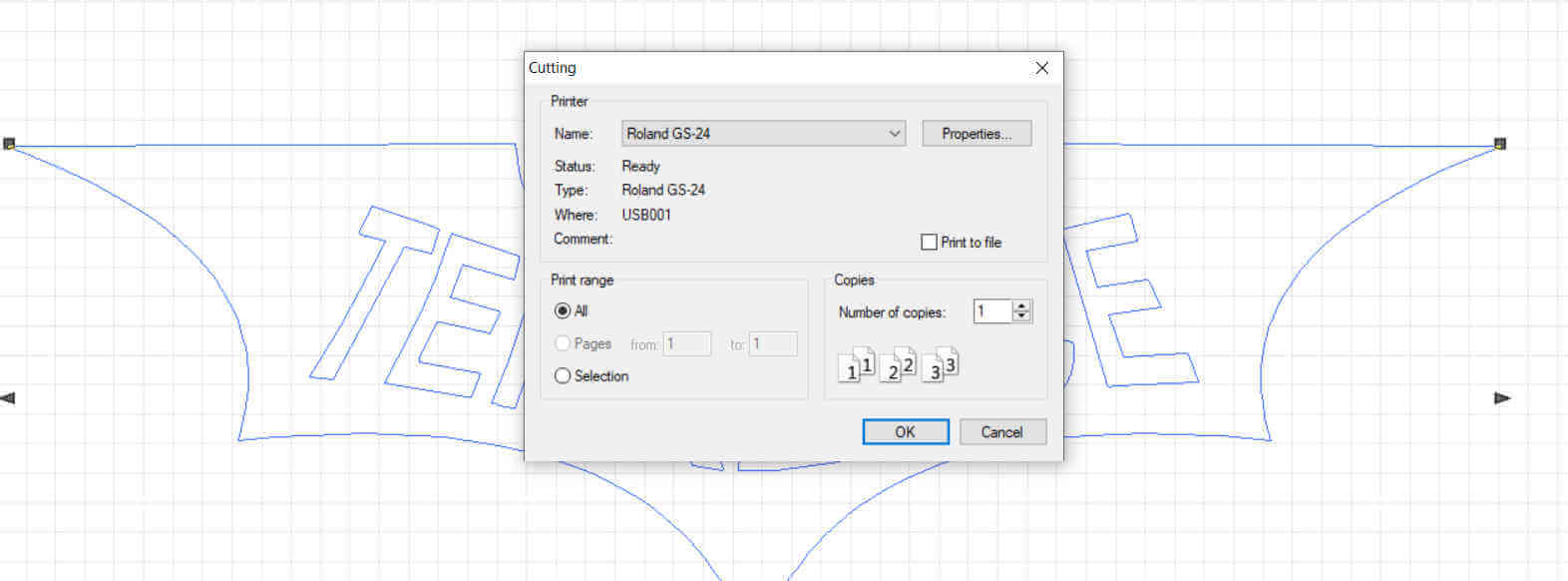
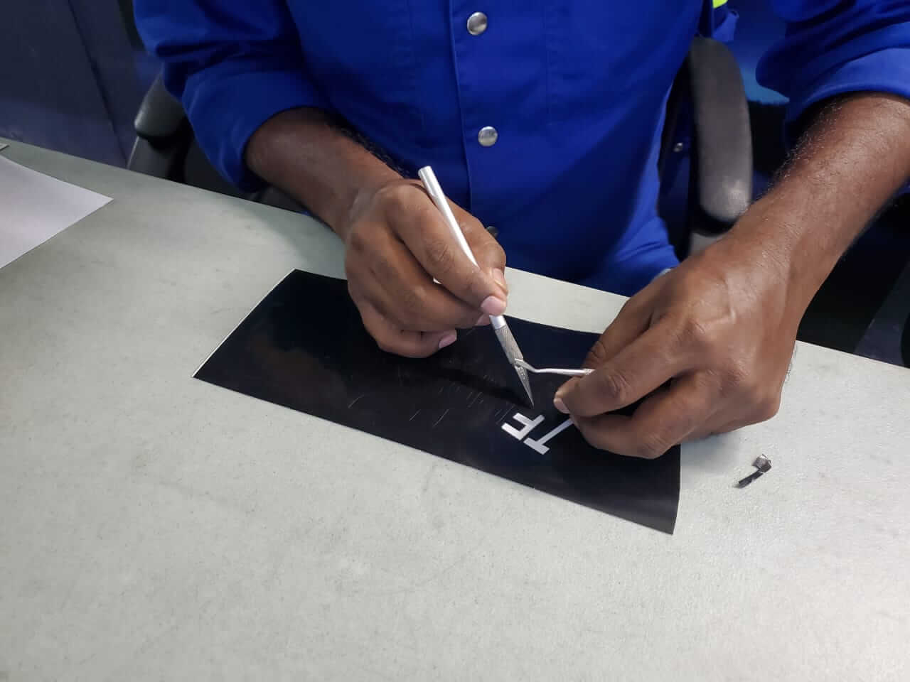
I selected the machine from Cut Studio and sent the image to be cut.
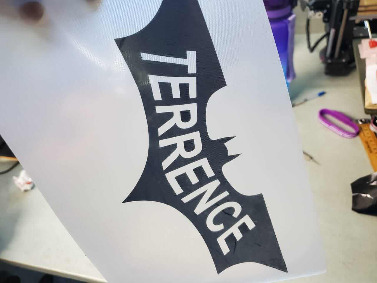
When the cutting was completed I removed the unwanted vinyl and I place transfer tape over the completed cut image.
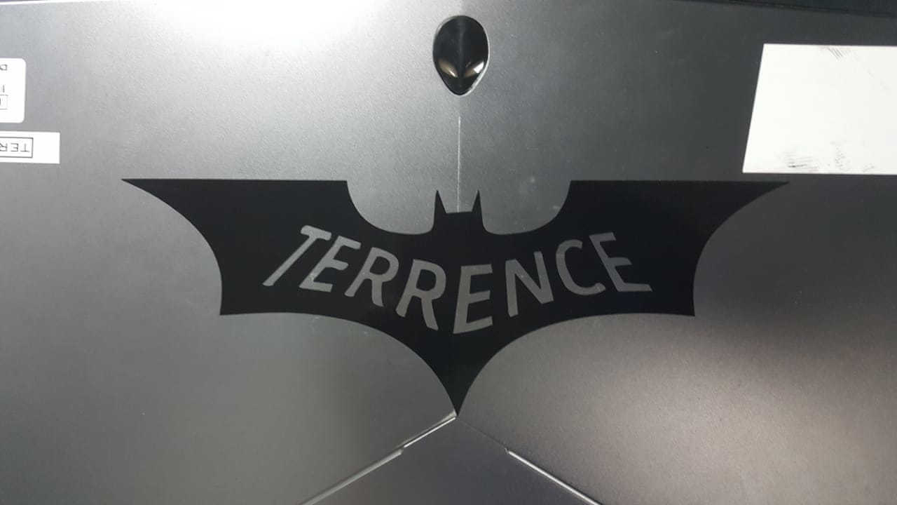
I stuck the image onto my laptop.
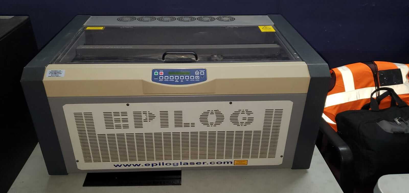
For this part of the assignment I used FreeCAD to design my press-fit kit which I cut using cardboard on one of my Lab's Laser cutters.
Our FabLab has 2 laser cutters:
Epilog Fusion 120
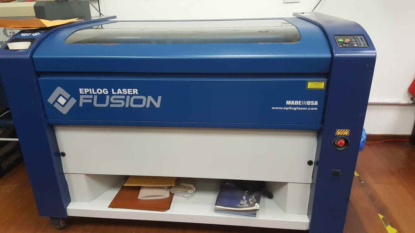
Epilog Mini Helix
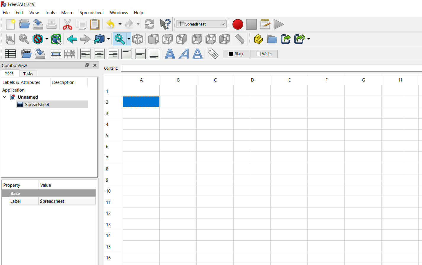
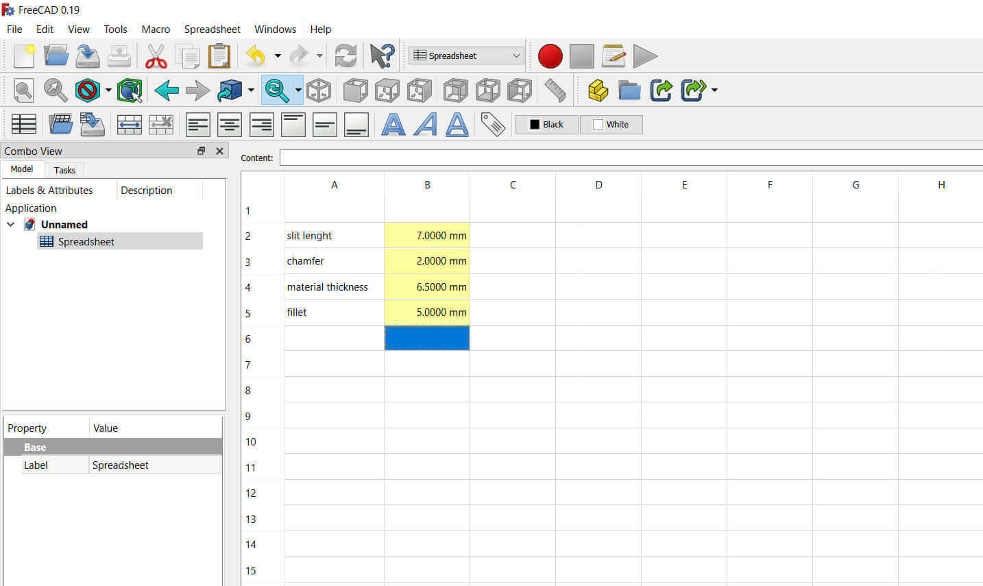
Firstly, I created a spreadsheet in FreeCAD to enter my fixed parameters.
The parameters were given names and values. I right clicked on the value cell to access my cell properties. I entered the unit the value would be measured in and also an alias to identify the specific parameter when required.
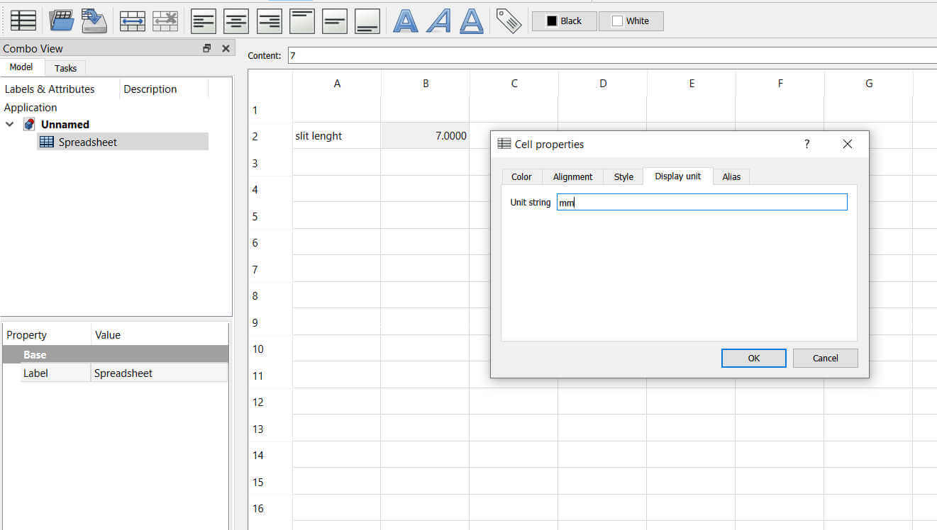
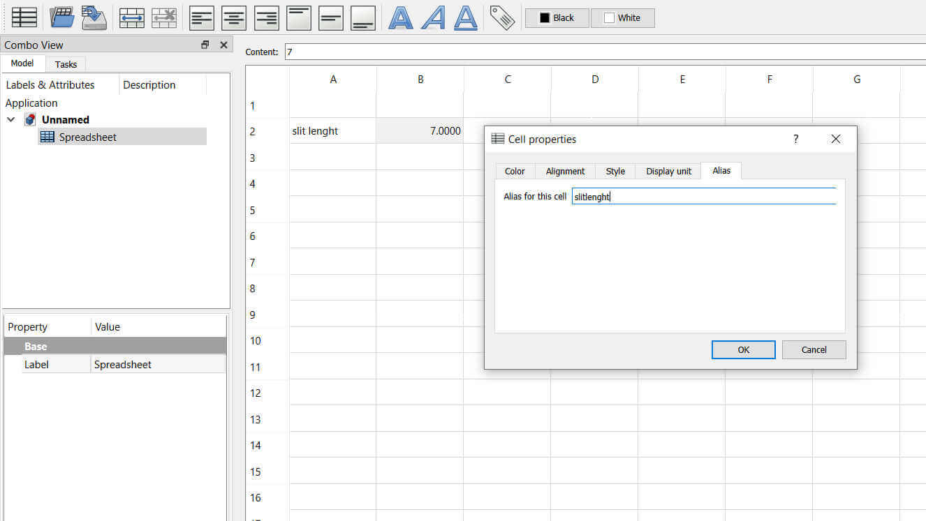
On completetion of adding the unit and alias, I noticed the value cell became yellow. This was confirmation that the fixed parameters were set. The value entered for the material thickness is the physical cardboard thickness minus the kerf value when cut from the laser.
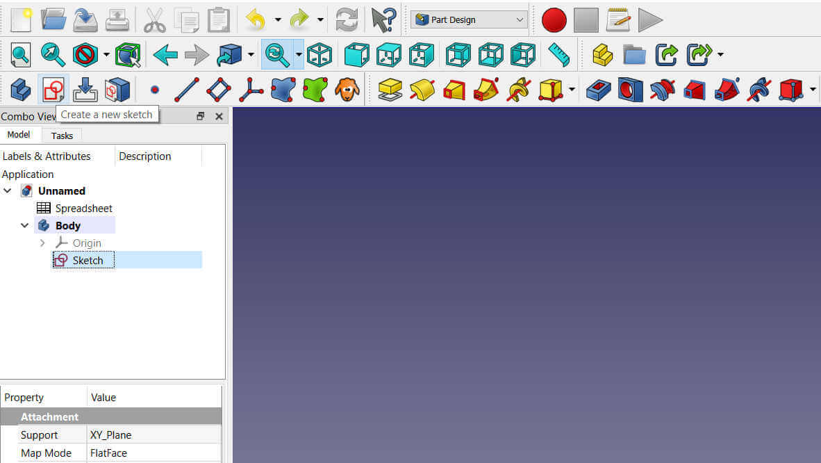
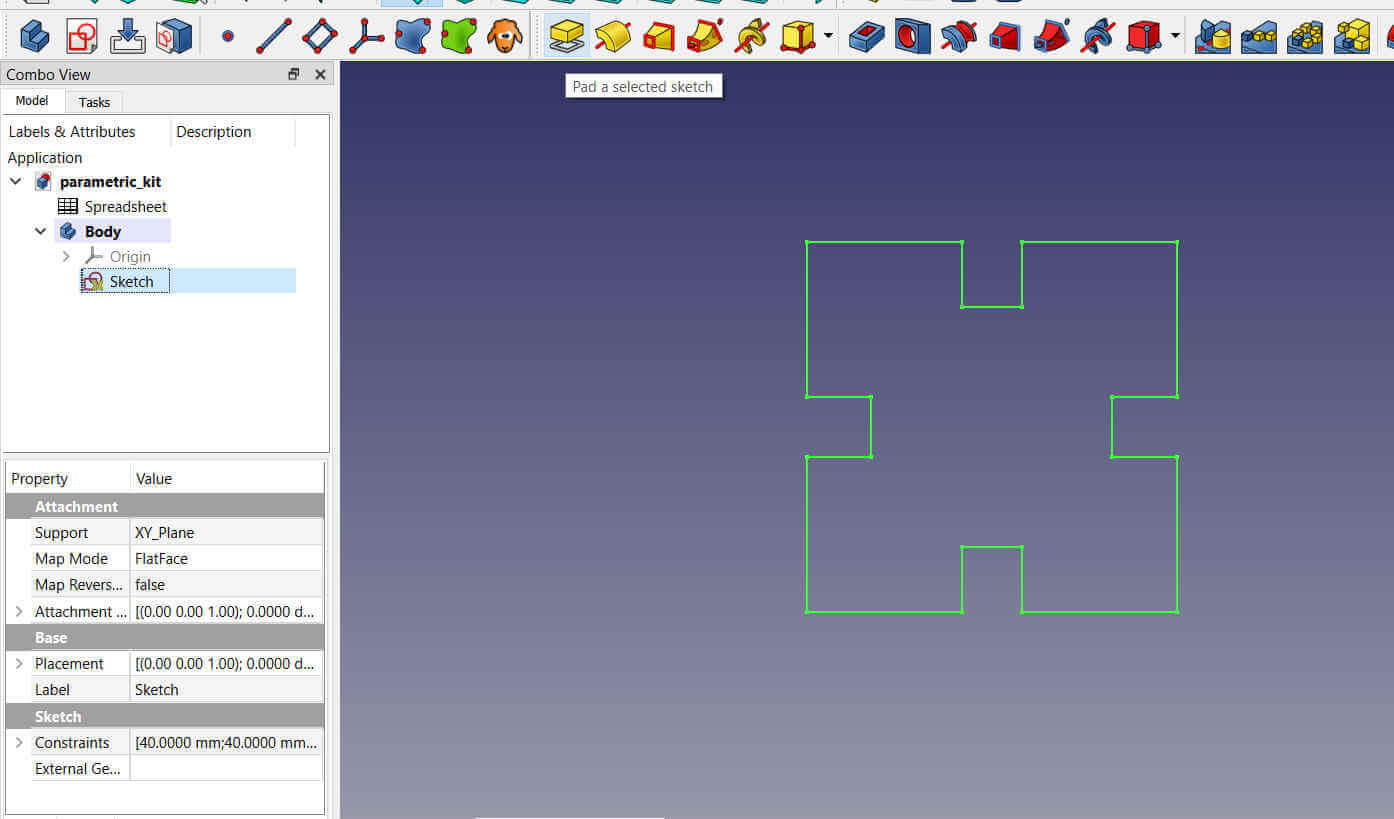
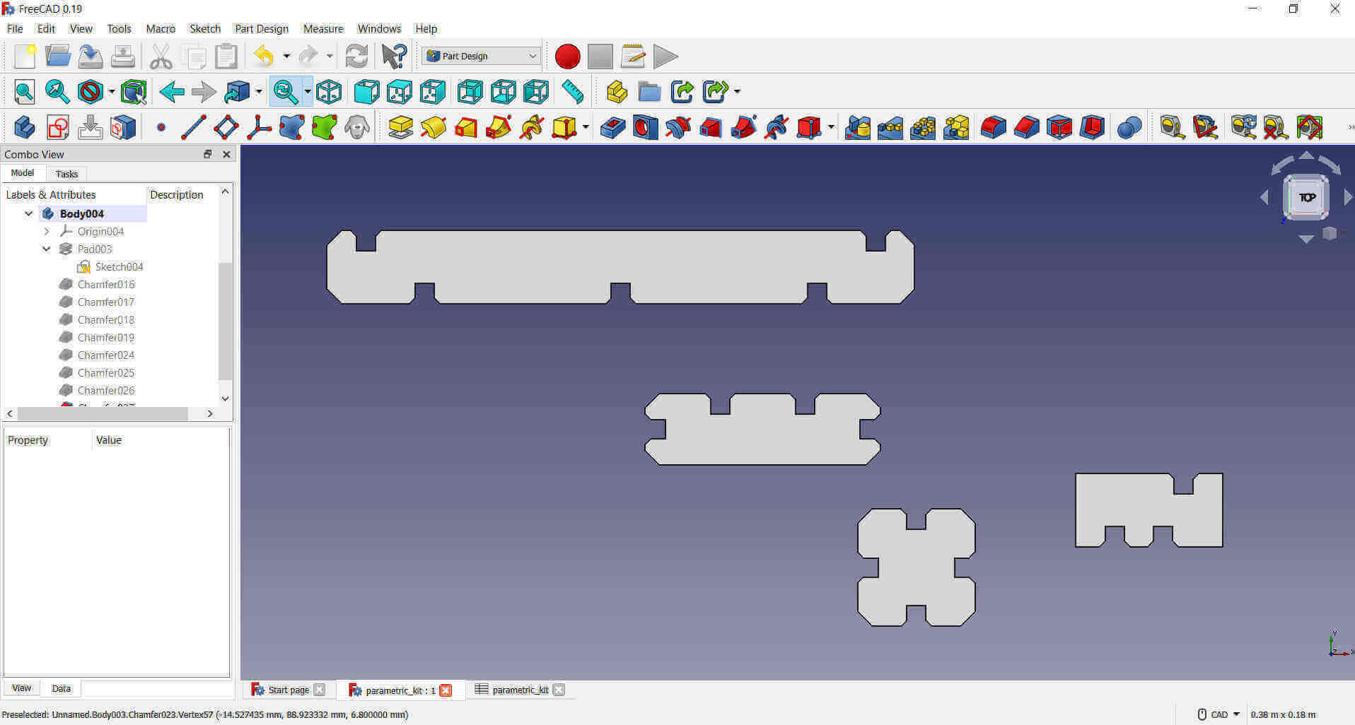
I selected the Part Design workspace, where I added a new Body. I then created a new Sketch.
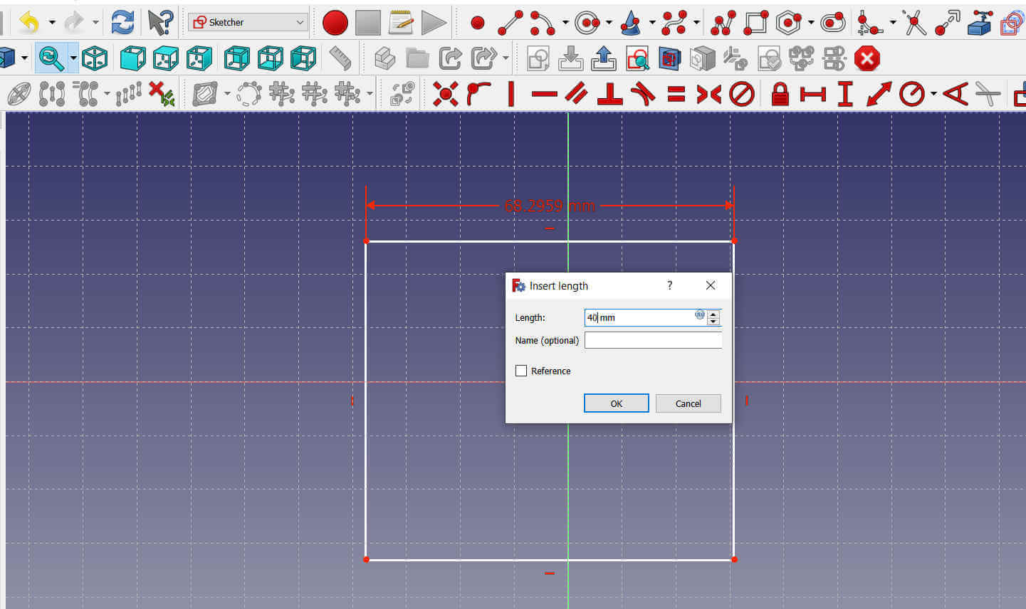
I used the Create a rectangle tool to draw a square.
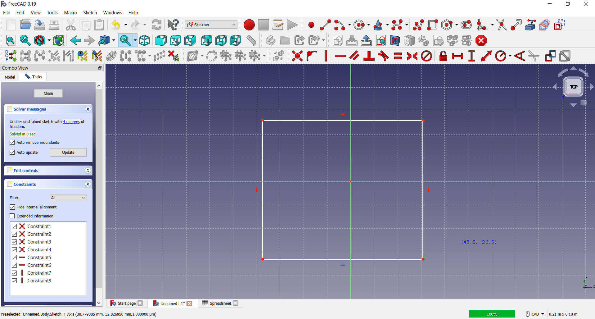
I added measurements of 40mm to the sides using the Fix Horizontal Distance and Fix Vertical Distancetools.
I added 4 rectangles intersecting the square on each side.
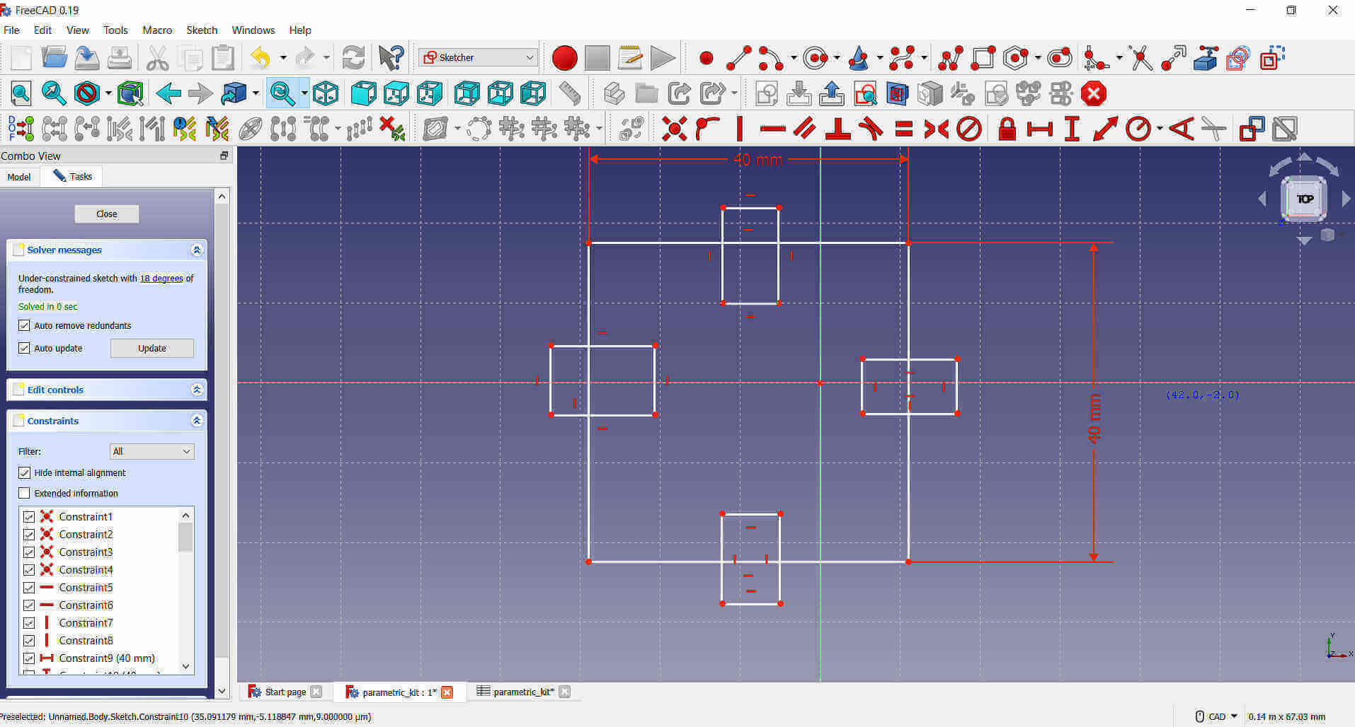
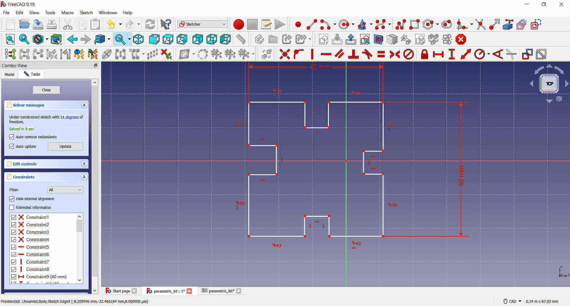
I then removed the unwanted parts using the Trim an edge tool.
The remaining parts of the rectangles are the slits where another part can slide and connect.
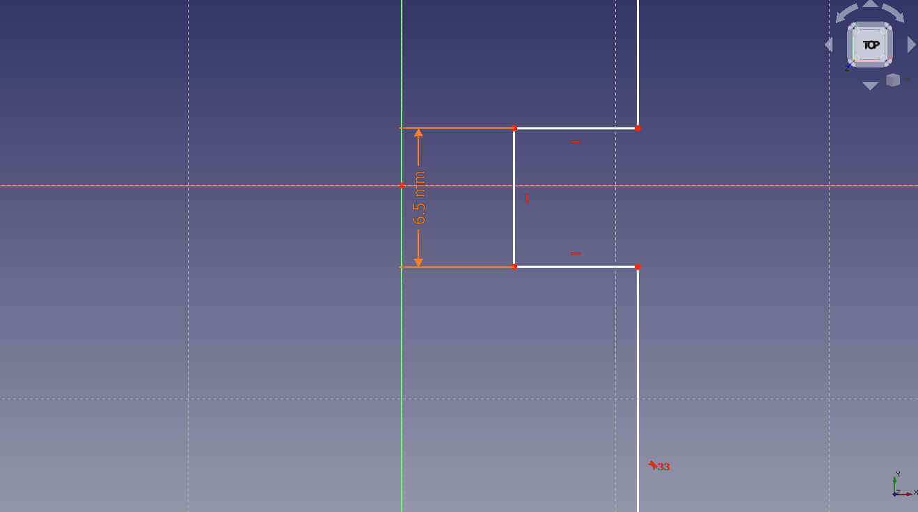
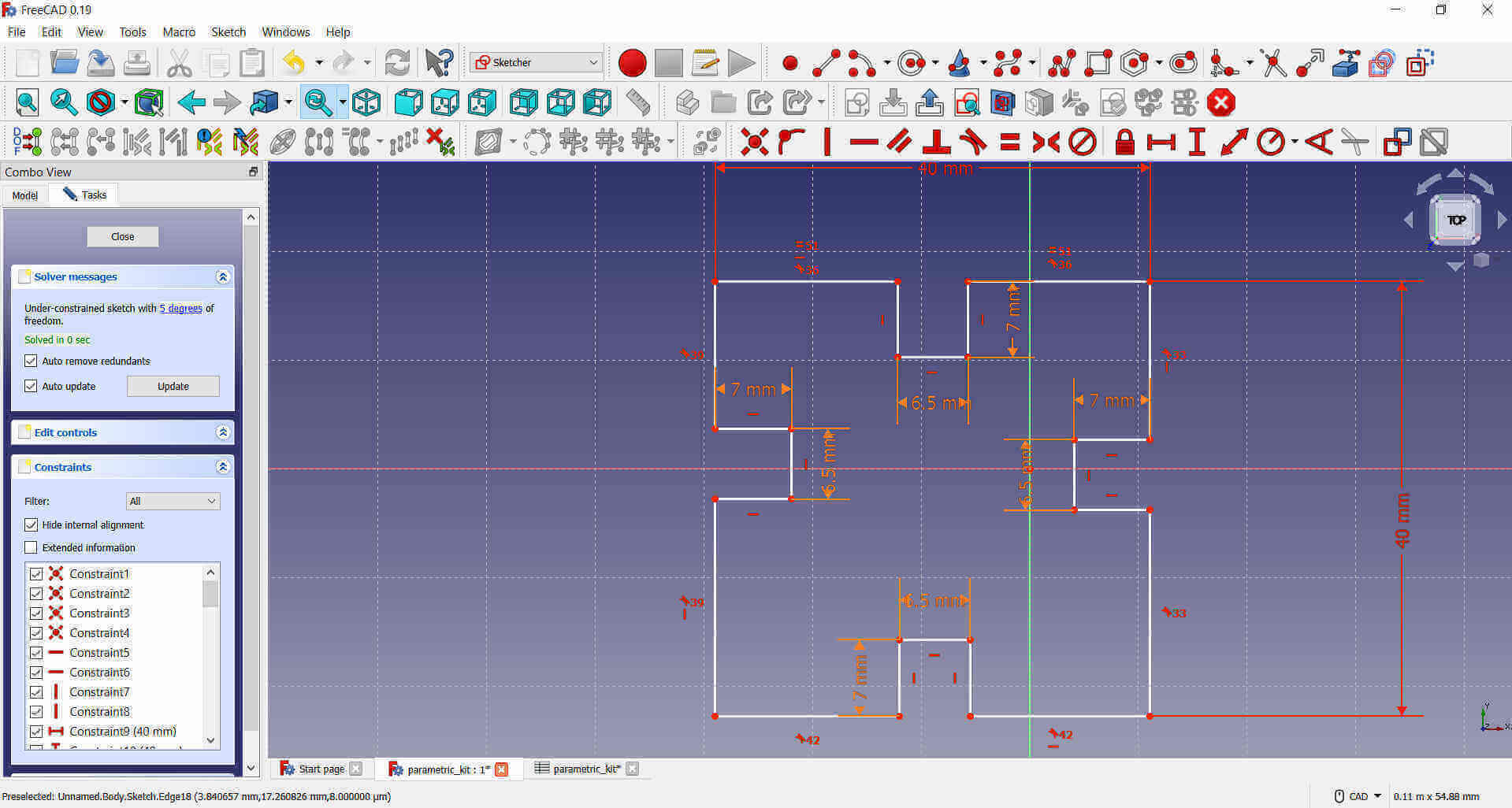
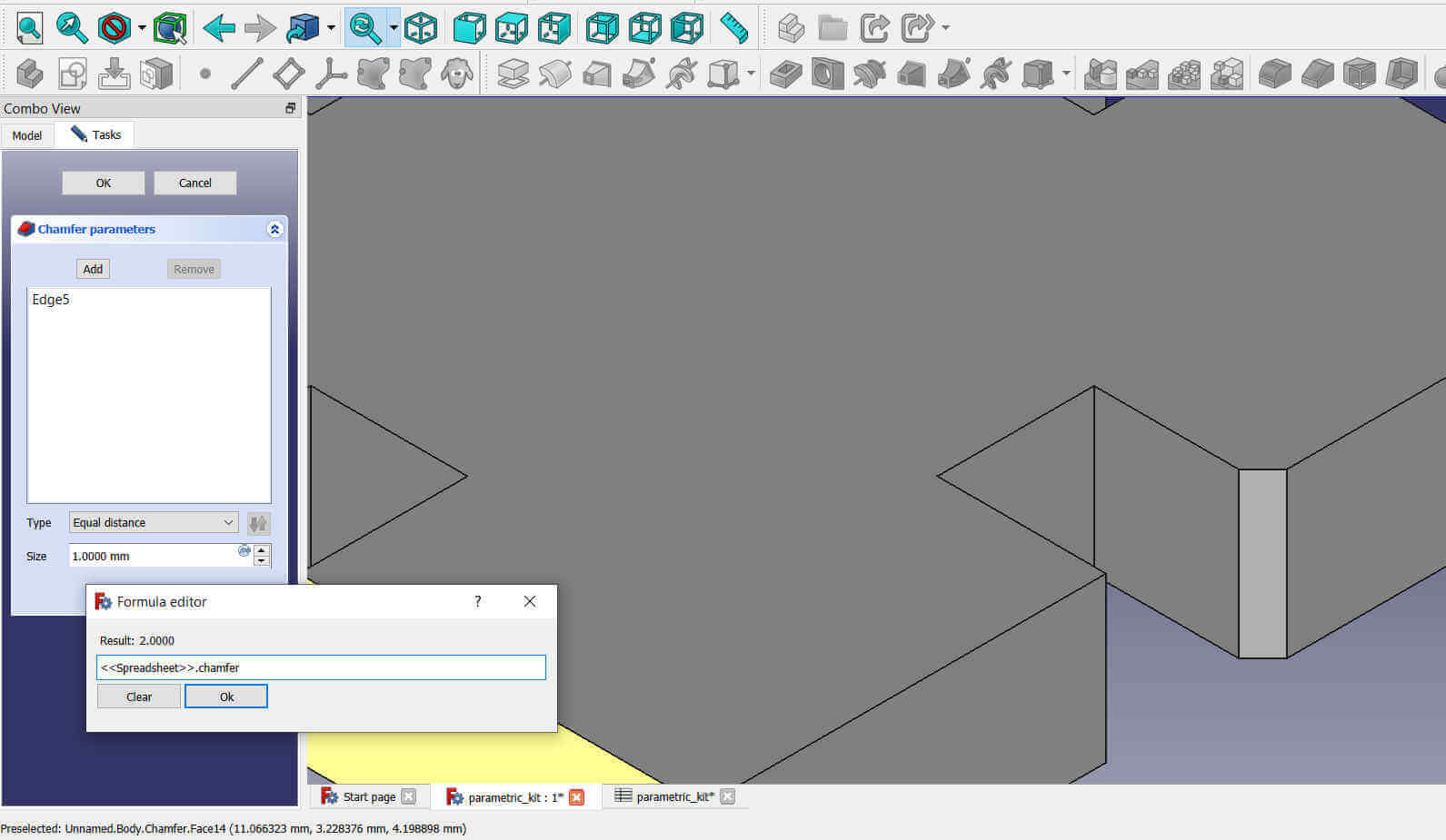
I used the Fix Distance tools to measurements to the slit. Instead of typing a number, I clicked on the little dot to the top right corner and a sub-window opened. This is where I referred to the spreadsheet as seen in the picture below, to pull and add the fix parameter by its alias.
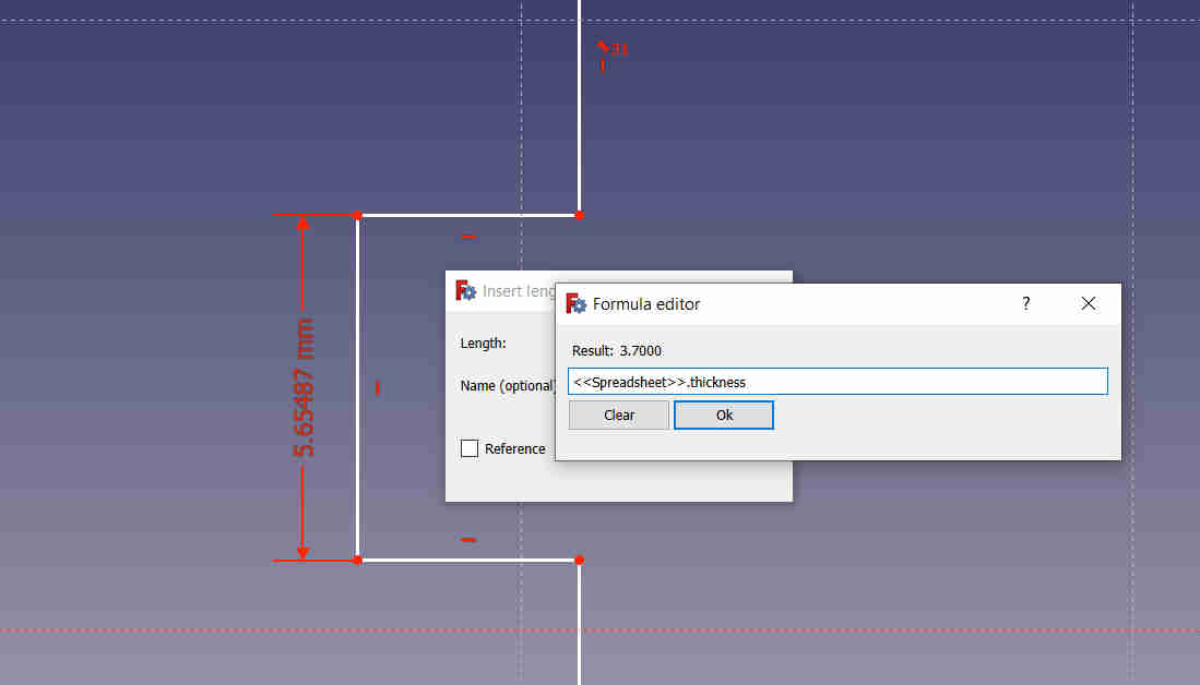
The measurement show as orange instead of red as confirmation that the alias value referred from the spreadsheet was added successfully.
All measurements using the same alias can be editted in the Spreadsheet. The reason for doing this is so that if I change the material I am going to use for my press-fit kit, I can just change the alias value in the spreadsheet to accomodate the thickness or size of the new material.
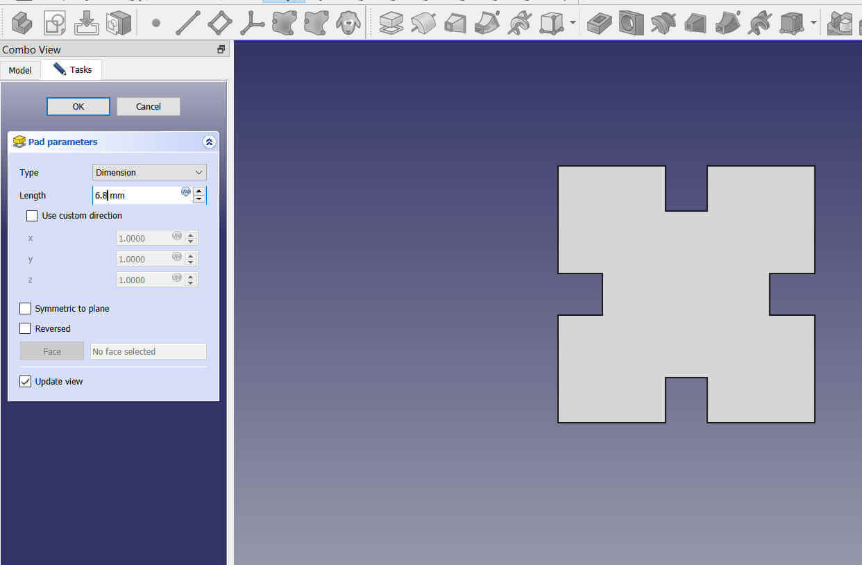
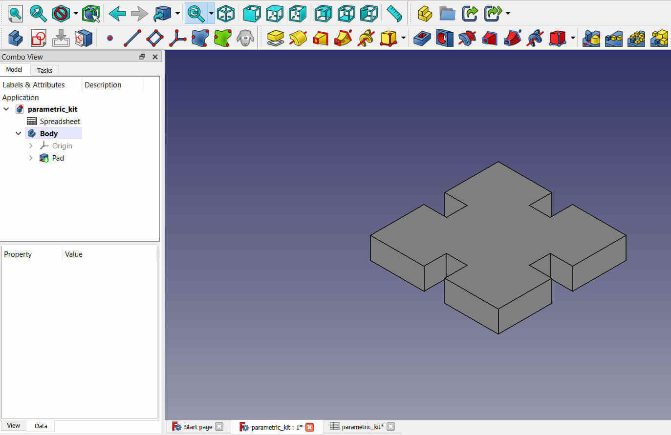
I need to add a little chamfer to the corners so the connecting parts will be easier and also to add a little style to the shape. I found that by Padding the object (adding thickness), makes it very easy to add Chamfers.
I selected the Padding tool and entered the thickness of the material. The thickness did not matter in this case because I was only adding it to use the Chamfer tool.
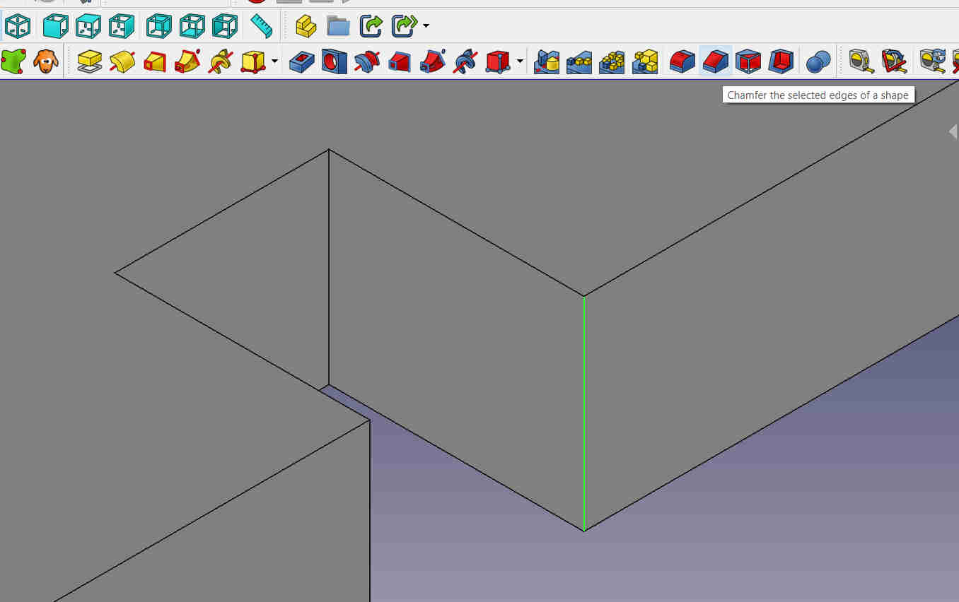
I select the edge that I wanted chamferred and selected the Chamfer tool. I called on the chamfer alias from the Spreadsheet for the slits and I also chamferred the corners of the object.
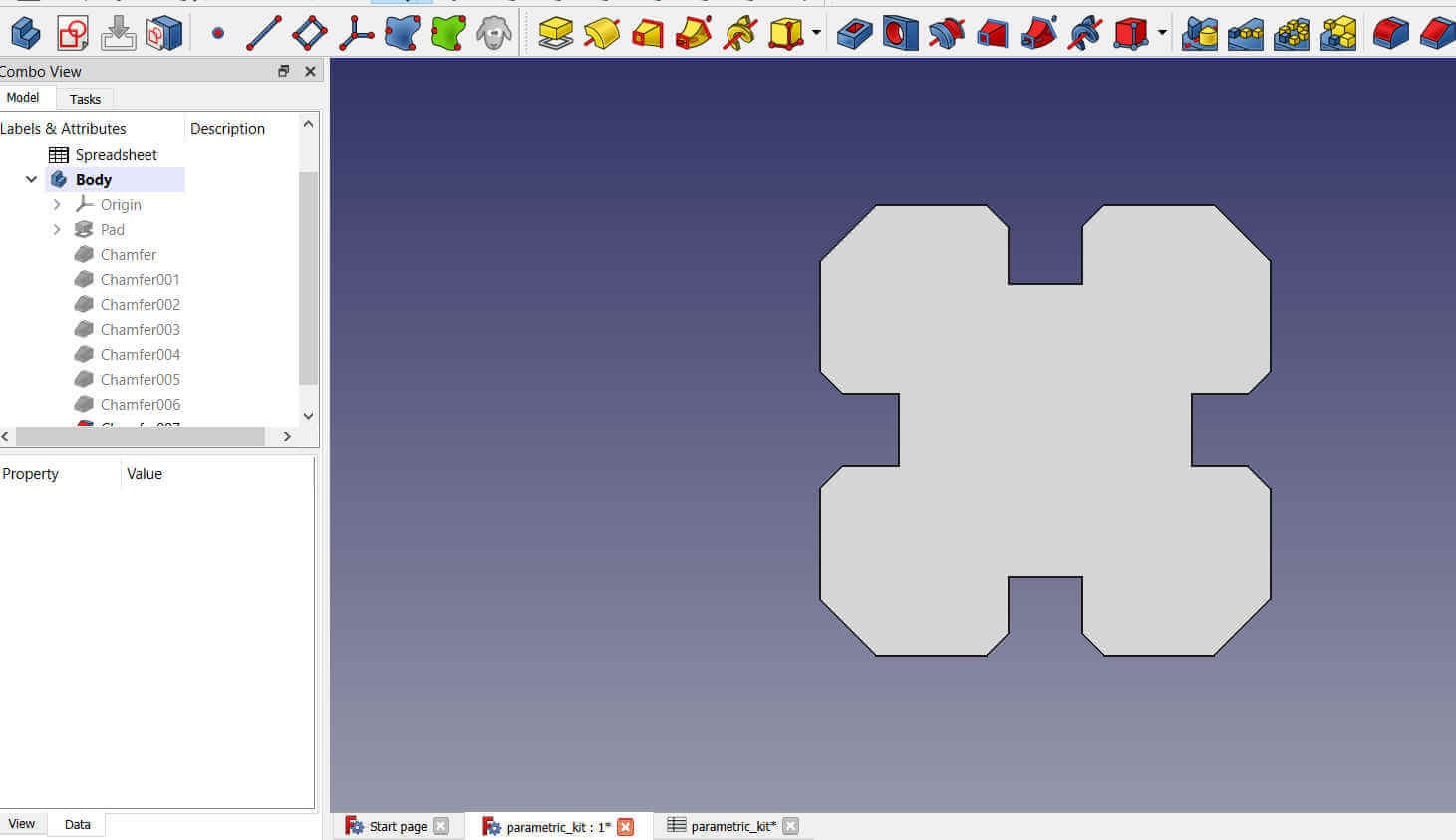
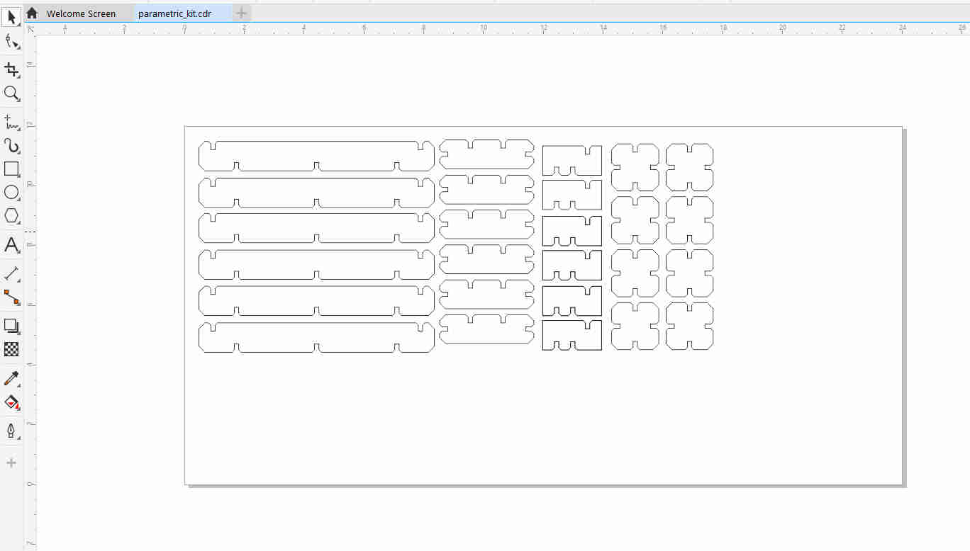
I designed additional objects to add to the kit using the same tools and procedure. The file was exported as .dxf format.
The .dxf file was then imported into CorelDraw to be prepped for the laser cutter.
Since the objects were padded in FreeCAD, they were double lined (a line for each side of the object). The 2nd line had to be
removed else the laser would have passed twice on the same spot which would have taken longer to cut and may have burned the cardboard.
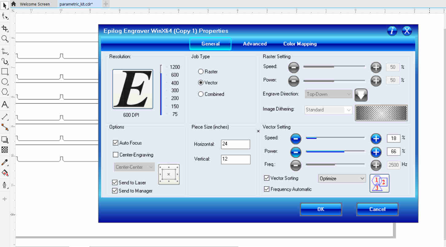
The file was then sent to the laser using the settings shown in the picture below.
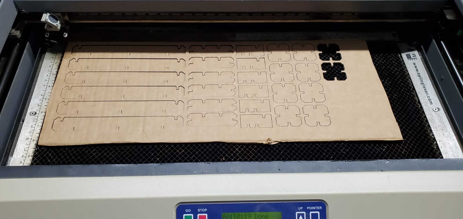
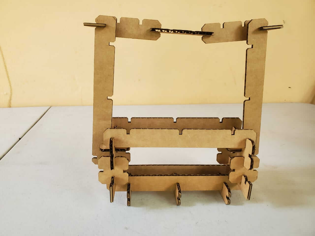
My completed press-fit kit.
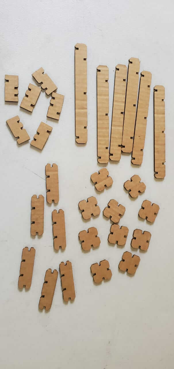
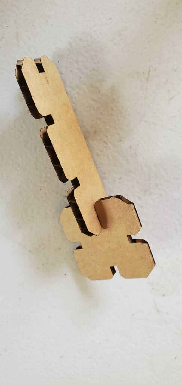
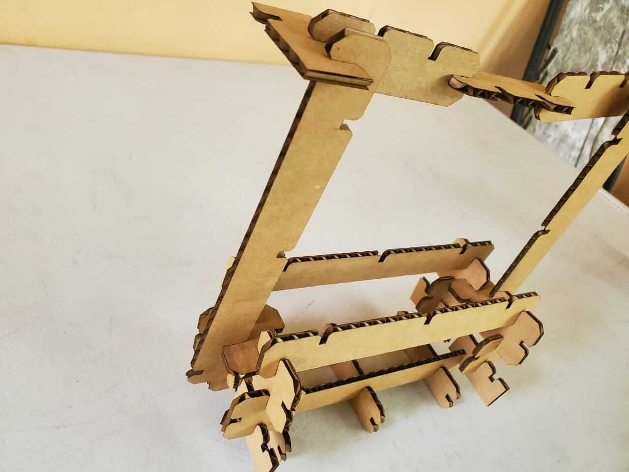
Can you guess what it is?