Fifteenth Week:
Interface and Application Programming
At this week assignment I decided to create a kind of Led Panel based on a mix between Output Assignment and Bluetooth communication system which will work with my ultimate processor device using an AtMega 328p called "AtomicMegatronic". Let's start.
Designing a Producing Part
First I had previusly decided to make a 5x5 matrix which help me to give a good performance for each letter but I realized there are not enough pins in/out to connect 25 outputs so I changed the matrix to a 3x3 and consequently I had to change the ways how some words would be showed.
Next will be showed how I decided to represent each letter. Starting with the concept.

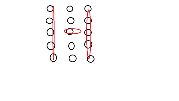
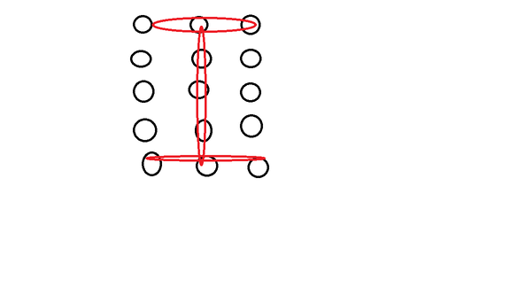
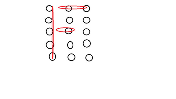
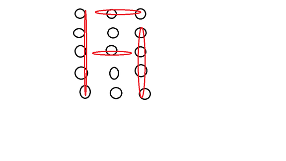

Note: As you can see, up says "HI FAB" and this is just the beginning.
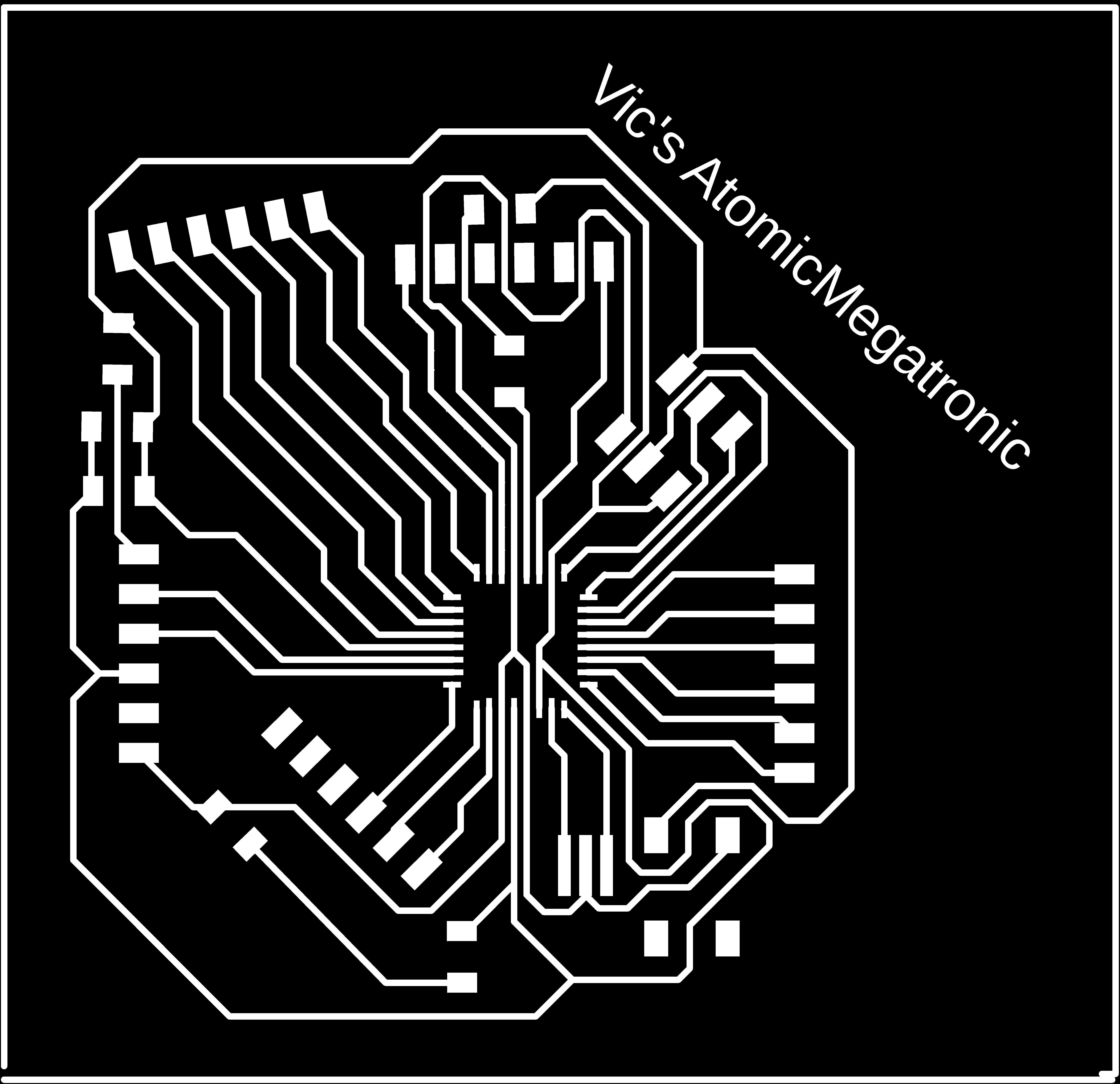
Now was time to decsign all boards I will use. I divided in 2 process: 1st which was for my AtMega, and 2nd for de panel.
At AtMega production I decided to use all pins.


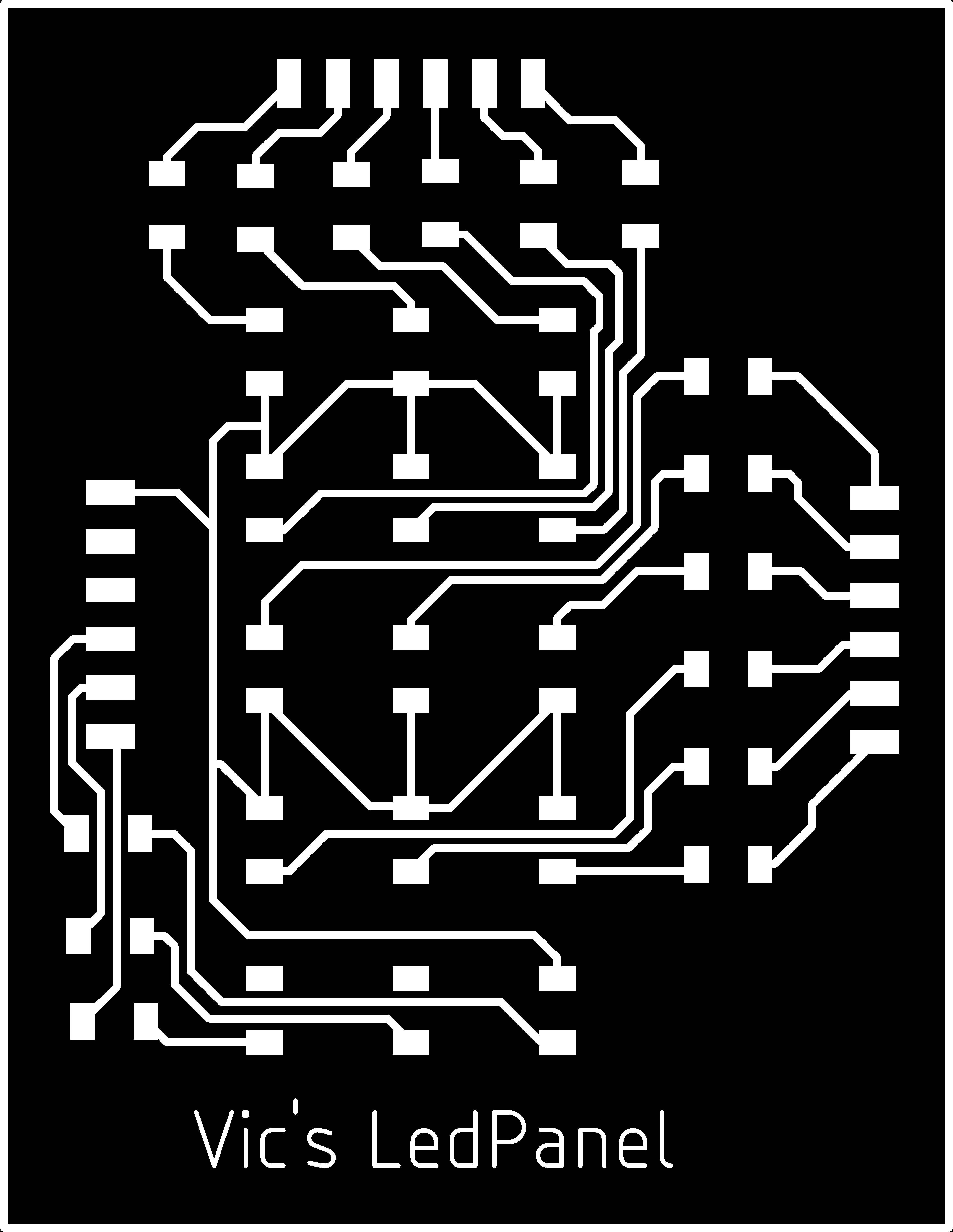
At Panel production I set all pins in groups which would be coupling with my AtMega board.


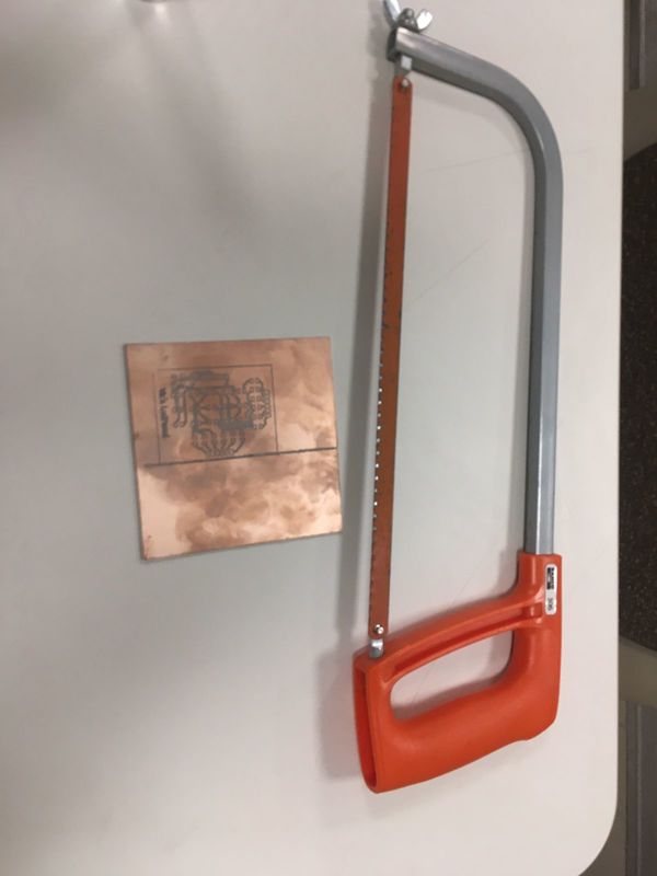
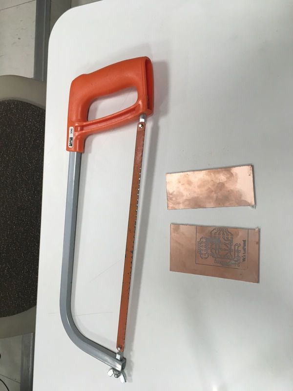
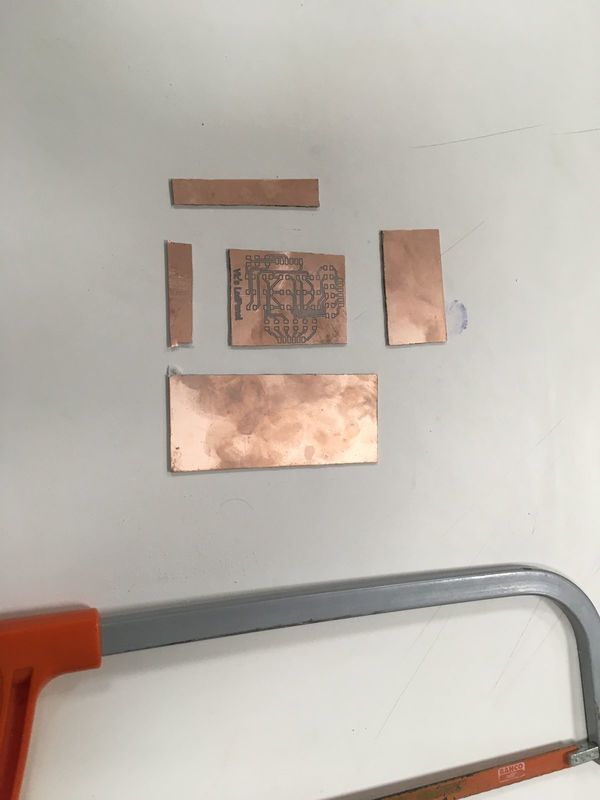
Then I had to cut all waste using a bow saw.
To finally solder all components

Assemblying and Testing
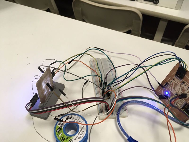
At this part I burned my AtMega bios. Then I had to diagram how both pins will be connect between these 2 boards.

Note: As you can see around all the paper I also sketched how letter and number will look, and how some numbers and words will be sharing or will be changed because in a 3x3 matrix there aren't much space to performance them like "M-N-H", "V-W", "G-6","O-Q-0-8","2-Z",and "5-S".
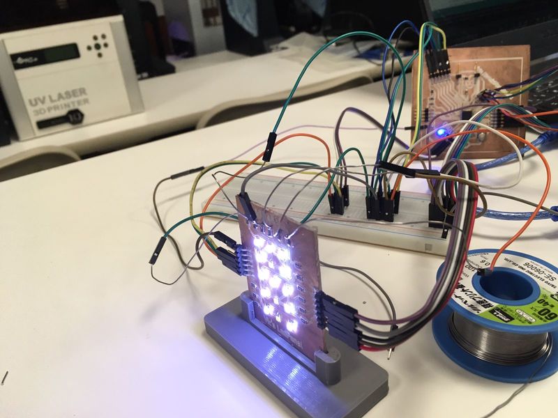
Having all this set I connected both boards and uploaded an simple code just to test all leds and pins performance.
int led=PD2;
int led2=PD3;
int led3=PD4;

int led4=A0;
int led5=A1;
int led6=A2;

int led7=A3;
int led8=A4;
int led9=A5;

int led10=10;
int led11=9;
int led12=8;

int led13=PD7;
int led14=PD6;
int led15=PD5;


void setup() {
// put your setup code here, to run once:
pinMode(led,OUTPUT);
pinMode(led2,OUTPUT);
pinMode(led3,OUTPUT);

pinMode(led4,OUTPUT);
pinMode(led5,OUTPUT);
pinMode(led6,OUTPUT);

pinMode(led7,OUTPUT);
pinMode(led8,OUTPUT);
pinMode(led9,OUTPUT);

pinMode(led10,OUTPUT);
pinMode(led11,OUTPUT);
pinMode(led12,OUTPUT);

pinMode(led13,OUTPUT);
pinMode(led14,OUTPUT);
pinMode(led15,OUTPUT);
}
void loop() {
// put your main code here, to run repeatedly:
digitalWrite(led,HIGH);
digitalWrite(led2,HIGH);
digitalWrite(led3,HIGH);

digitalWrite(led4,HIGH);
digitalWrite(led5,HIGH);
digitalWrite(led6,HIGH);

digitalWrite(led7,HIGH);
digitalWrite(led8,HIGH);
digitalWrite(led9,HIGH);

digitalWrite(led10,HIGH);
digitalWrite(led11,HIGH);
digitalWrite(led12,HIGH);

digitalWrite(led13,HIGH);
digitalWrite(led14,HIGH);
digitalWrite(led15,HIGH);
delay(50);
}


"It's Aliveee!"
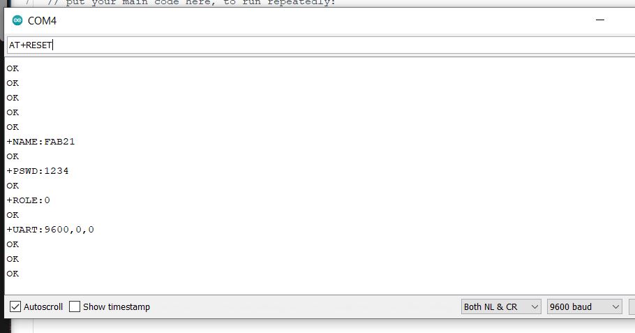
At this part I decided to use a Bluetooth module specifically the "HC-05".

I followed some tutorials to set the bluetooth name, password, UART, and its role.
To summarize I used the next commands after I restarted all configuration to fabric using "AT+ORGL":
Name: AT+NAME="put here the name"
Password: AT+PSWD="put here the password"
Role: At+ROLE="put here 0 to define it as a slave, or 1 to be a master"
UART: AT+UART="put here your number in the next sequence: "NUMBER,0,0""
Note: To ask the preset of each part you nedd to change the "=" for an "?" and just press enter.

And finally to restart and continue with this assignment just put "AT+RESET" and your bluetooth would be working as you defined.
Having all of this done I decided to create a holder for mi panel board at Fusion 360.
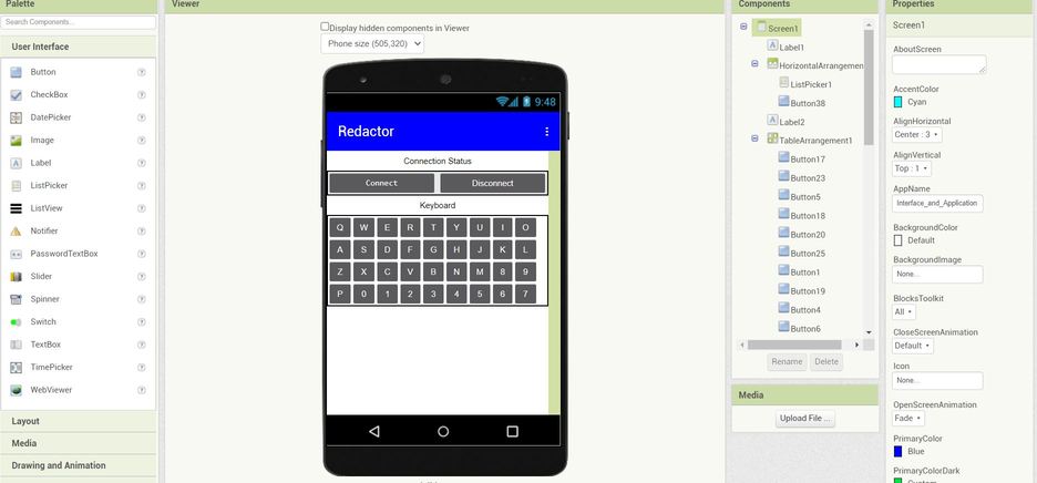
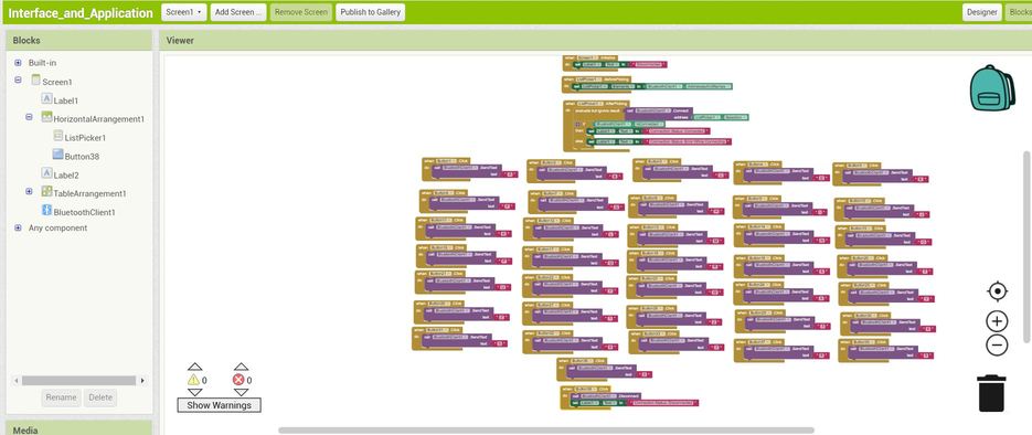
Finally I used AppInventor to create an app to control it.
Now was time to assembly and use them.
I used a new code which I put below at files because it's very long. Let's take a look of the first part.

Let's take a look.