Thirteenth Week:
Output Devices
At this week assignment we had to design, mill, solder and program a board which can do something using its pins as outputs.
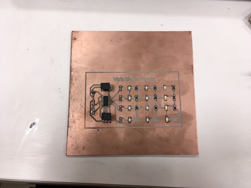
I decided to make a Led Array board which can be find here with a 3x4 matrix.
Designing and Production Part
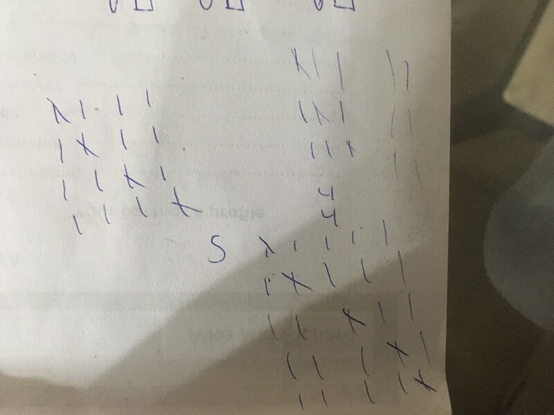
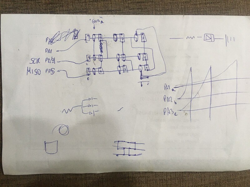
Before design the board at Eagle's software I try to understand "How it works" doing sketches by hand.
At the beginning I tried to design a 3x3 matrix and I didn't understand why it does not work. Then, doing my sketches I understood the proportion of this kind of matrix which is AxB, B=A+1.
Having understood how it works I had to decide which microprocessor I would use. For this number of outputs I decided to use a medium processor which is an AtTiny44.
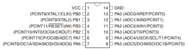
Here is a very useful picture of an AtTiny44 pins description made by Inés Ariza.
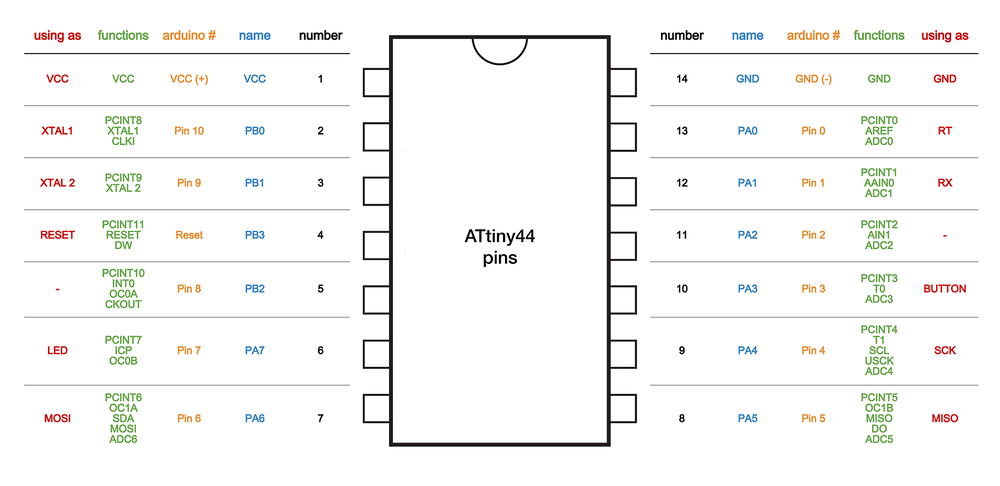
With this information I decided and defined the pins I will use: from PA1 to PA4, setting those as output rows.
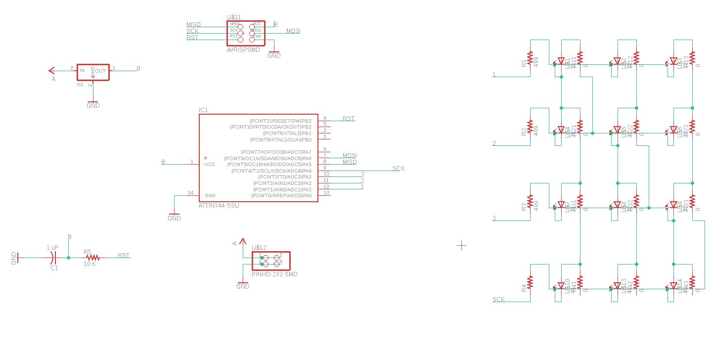
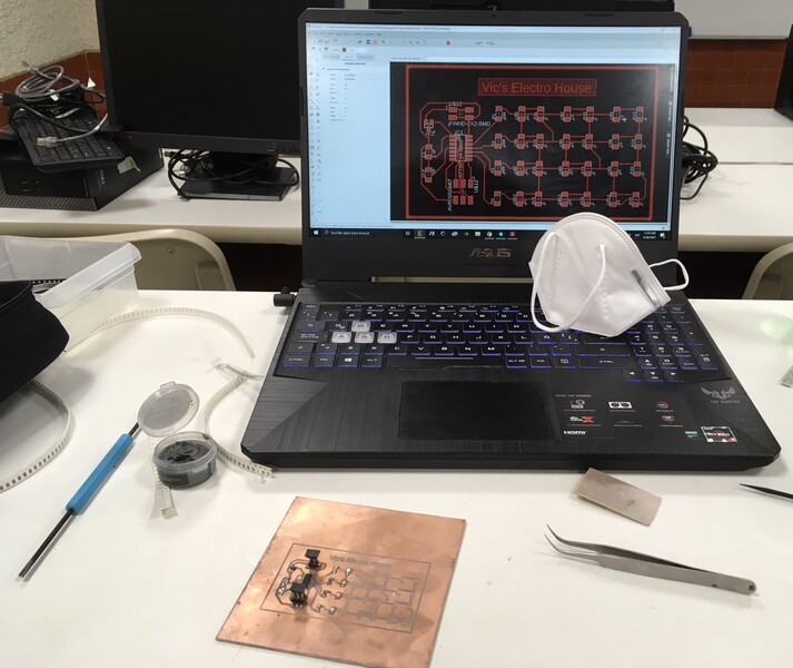
Now was time to desing it at Eagle. Starting with the schematic part.
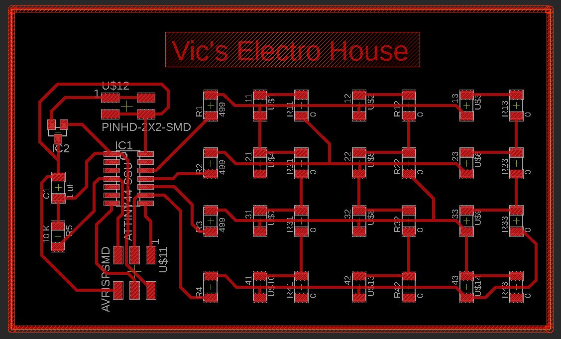
Following with the board part.
And using the Fab Modules to create the G-Code as I learnt weeks ago.
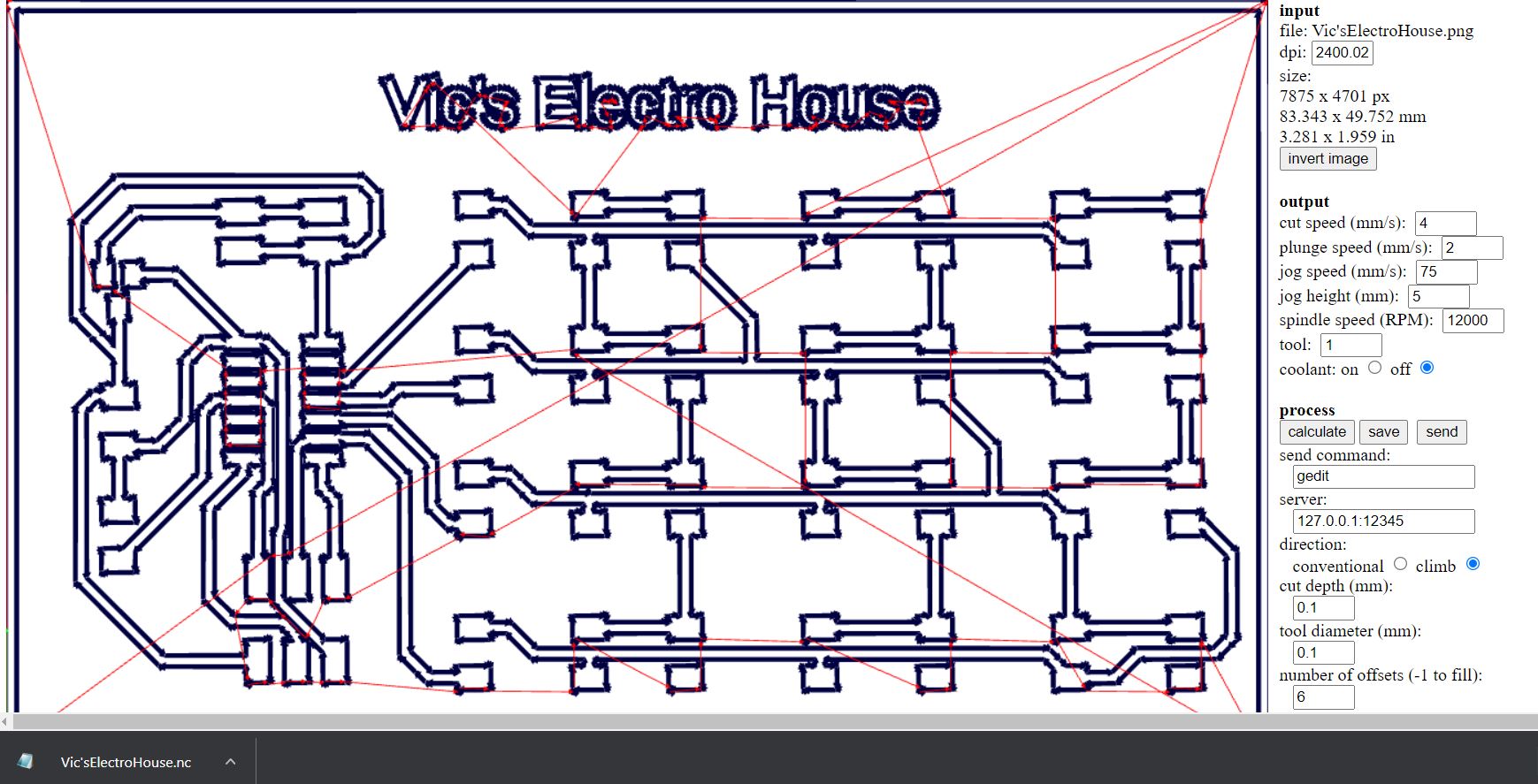
To finish with the milling process at Roland machine.
Soldering Part
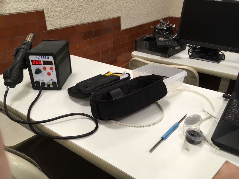
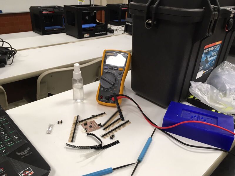
At that time, when I was doing this assignment, the Fab laboratory was moved to other building so I had to organize my new workspace.
Left side
Right side
Then I started to the solder process.
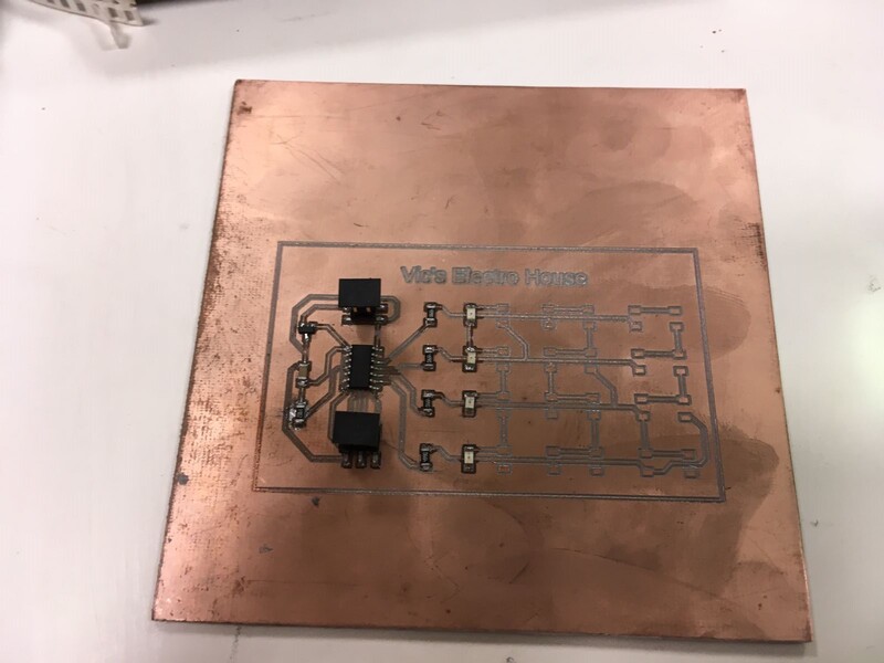
Having at last this.
Programing and Finishing Part
To finish I had to connect it through my ISP, which I fabricated at Electronic Production assignment to start with the burning part.
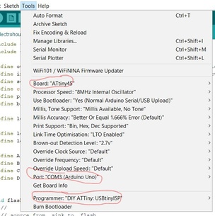
Having burned I used the next code to set. Take notes.
#include <avr/io.h>
#include <util/delay.h>

#define output(directions,pin) (directions |= pin) // set port direction for output
#define input(directions,pin) (directions &= (~pin)) // set port direction for input
#define set(port,pin) (port |= pin) // set port pin
#define clear(port,pin) (port &= (~pin)) // clear port pin
#define pin_test(pins,pin) (pins & pin) // test for port pin
#define bit_test(byte,bit) (byte & (1 << bit)) // test for bit set

#define led_delay() _delay_ms(1) // LED delay

#define led_port PORTA
#define led_direction DDRA

#define A (1 << PA1) // row 1
#define B (1 << PA2) // row 2
#define C (1 << PA3) // row 3
#define D (1 << PA4) // row 4


void flash(uint8_t from, uint8_t to, uint8_t delay) {
   //
   // source from, sink to, flash
   //
   static uint8_t i;
   set(led_port,from);
   clear(led_port,to);
   output(led_direction,from);
   output(led_direction,to);
   for (i = 0; i < delay; ++i)
       led_delay();
   input(led_direction,from);
   input(led_direction,to);
   }

void led_cycle(uint8_t number, uint8_t delay) {
   //
   // cycle through LEDs
   //
   uint8_t i;
   for (i = 0; i < number; ++i) {
      flash(B,A,delay);
      flash(C,A,delay);
      flash(D,A,delay);
      flash(A,B,delay);
      flash(C,B,delay);
      flash(D,B,delay);
      flash(A,C,delay);
      flash(B,C,delay);
      flash(D,C,delay);
      flash(A,D,delay);
      flash(B,D,delay);
      flash(C,D,delay);

      }
   }

int main(void) {
   //
   // set clock divider to /1
   //
   CLKPR = (1 << CLKPCE);
   CLKPR = (0 << CLKPS3) | (0 << CLKPS2) | (0 << CLKPS1) | (0 << CLKPS0);
   //
   // main loop
   //
   while (1) {
      led_cycle(1,100);
      led_cycle(3,20);
      led_cycle(100,1);
      }
   }
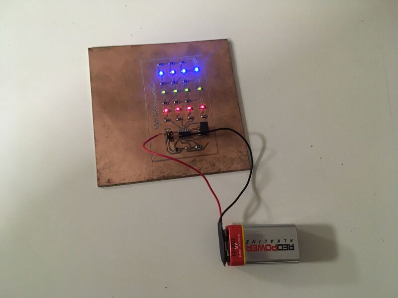
Then I test it with just GND and VCC wires.
To finally use a battery.
Take a look how it would look at "night", I just turned lights off.
Problems and Issues
1. As I said before, the laboratory had to move to other building in the same campus because this lab is inside the University of Lima. Due to that, I spent about a day and half to move my personal things, project and material which I used or will use, and the other half to organize my workspace at new location.
2. I had problem with the soldering machine which was a different function to the other I used.
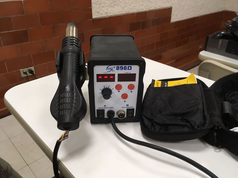
It has an automatic ON/OFF function which confused me when I tried to solder a component.
Making me do this.
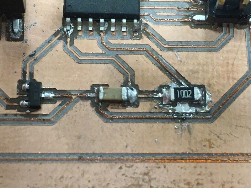
After some fails I found the correct time when the machine is optimal to solder that is holding it 10 seconds.