Eleventh Week:
Input Devices
Recognizing our Sensors
For this assignment we had to learn about sensors. There are 2 types: Analogic and Digital. Next, there is a video which explain what digital or analogic means when we talk about sensors.
As you could watch the differences or, to be more clearly, the benefits and cons are quite explain in this page.
Having know more about sensor I checked which ones we own.
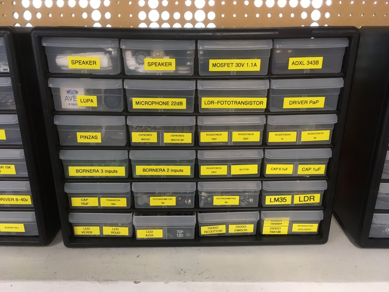
And create a table to sort them.
Finally, having research all this information I chose which sensor or sensors I would've been working with.
Knowing more about Hall Effect Sensor
Hall Effect Sensor has been known for over a hunndred years. Its first practical application outside of a laboratory was in 1950s when was used as a microwave power sensor. Nowadays is used in many products as computer, sewing machine, automobiles, etc.
This sensor works based on the Hall Effect which refers to the production of a voltage difference across an electrical conductor that is transverse to an electric current in the conductor, that in our case supply by our processor and its pins, and to an applied magnetic field perpendicular to the current.

Note: 1. Current, 2. Flat Conductor (Hall Element), 3. Magnet (Whatever magnet that will create a voltage difference), 4 Magnetic Field (That is result of the electromagnetism), and 5. Power source.
Here is a GIF which will represent how a Hall Effect Sensor works. The spinning object is creating a voltage difference that you can see as a yellow dot.
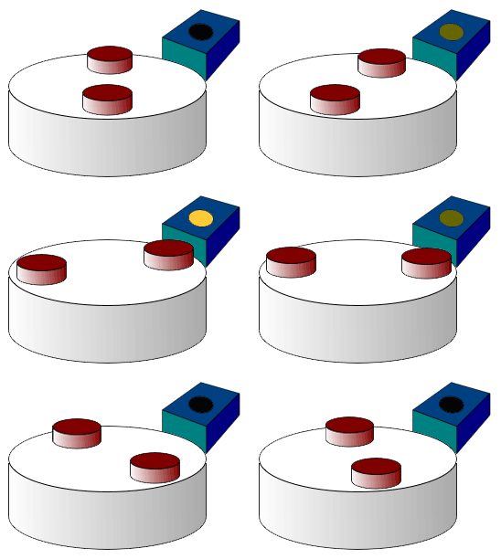
In its datasheet especify about the applications. It will be used as:
*Flow Rate Sensor that use Hall Sensor and magnets mounted in a wheel that every time of a magnet pass close to the hall will be a voltage change.
*Proximity Sensor that is quite simple one side has Hall Sensor and the other magnets, between each magnet and sensor there is a measure could be 10 centimeters. Parallel moving a side while create other state on the other side that can be measure.
*RPM Sensor that is similar to the first but you just need a magnet.
Fabricating my sensors
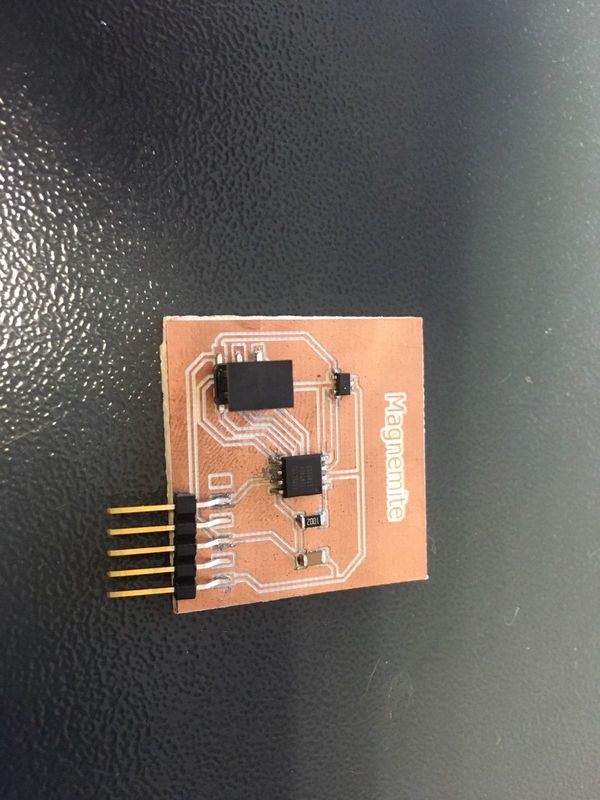
I decided to design a Hall sensor device and an Accelerometer device based on this Input Device page.
I started designing in Eagle my schematic and board device.
Then, I milled in Roland and soldered.
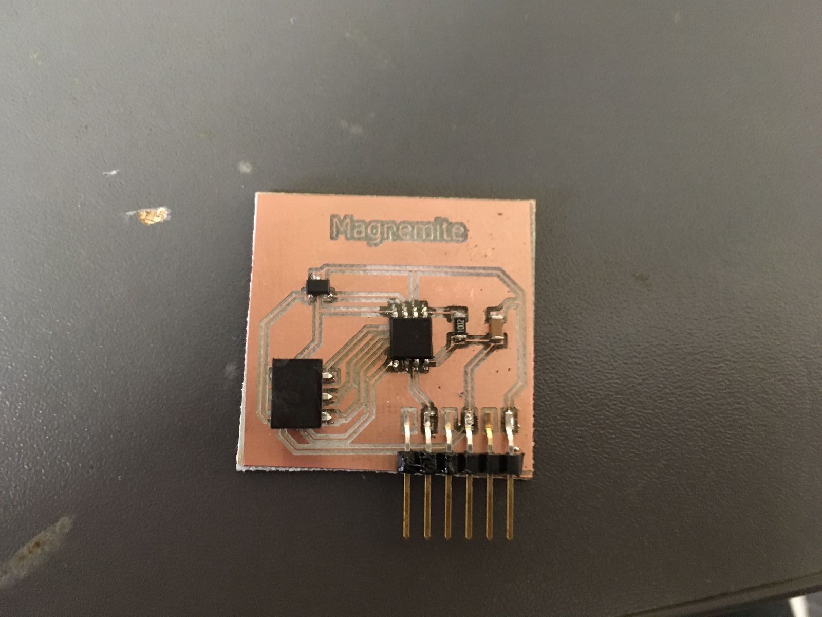
Note: I apologize about the appearance of my board. I had a problem with some solder unions with the proccesor, AtTiny45, which weren't well soldered. I had to do some reflows operations to soldered it well.
Time to burn the bootloader and program it. For this part I used Arduino IDE connecting this board with my ISP made on Electronic Production.
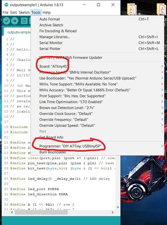

Then I uploaded Neil's code from here.
Using and Measuring the Sensor
Having all done I had my board ready to use.
First I test the signal at an oscilloscope as you can watch at next video. Setting 5V from a supplier and using a magnet.
Note: As you can see the signal gets expanded or contracted depending of which "face" of the magnet is in contact with this sensor.
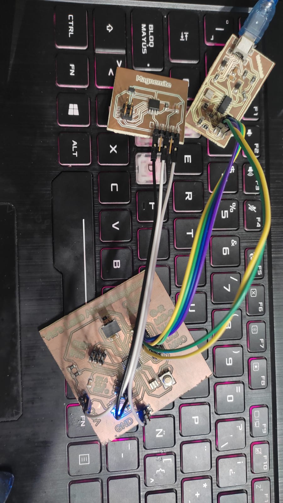
Now I used my ultimate AtMega board that you can find here , a tutorial found here and a magneted screwdriver. Let's watch the result.
But first the integration
And 2nd, the code
 volatile byte half_revolutions;
 unsigned int rpm;
 unsigned long timeold;
 void setup()
 {
   Serial.begin(9600);
   attachInterrupt(0, magnet_detect, RISING);//Initialize the intterrupt pin (Arduino digital pin 2)
   half_revolutions = 0;
   rpm = 0;
   timeold = 0;
 }
 void loop()//Measure RPM
 {
   if (half_revolutions >= 20) {
     rpm = 30*1000/(millis() - timeold)*half_revolutions;
     timeold = millis();
     half_revolutions = 0;

   }
   else if (half_revolutions <20){
    Serial.println("Not Detected");
   }
 }
 void magnet_detect()//This function is called whenever a magnet/interrupt is detected by the arduino
 {
   half_revolutions++;
   Serial.println("Detected");
 }
Note: This works whenever the Hall effect sensor detects a magnet, it outputs a HIGH (5V) voltage to its pinout. The interrupt pin of my AtomicMegatronic that is connected to that pinout detects this rising (HIGH) voltage through the function: magnet_detect. The status changes from "Not Detected" to "Detected" whenever a magnet is brought close to the sensor.
Here is the result
Files
Below you will find my files which I made this week.