Seventh Week:
Computer-Controlled Machining
To this assignment we had to design, mill and assembly something big like a chair, table, etc. I finally decided to build my own desk, but before that I will show you my learning process.
Let me introduce the machine
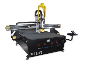
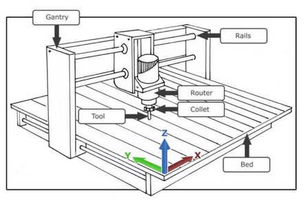
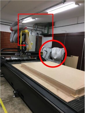
The machine I used is the MultiCam 3000 which is a beautiful and useful machine for this assignment.
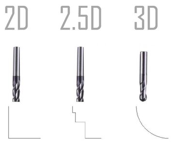
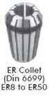
This is a 3-axis machine and also can work in 2.5 D design, and it uses compressed air to hold the tool and a ER8 to ER50 Collet. Next is a schematic picture of these kind of machines and its axis.
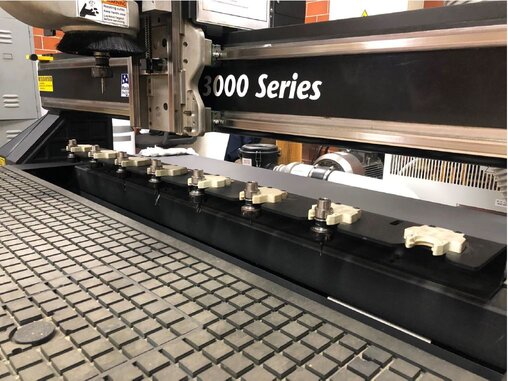
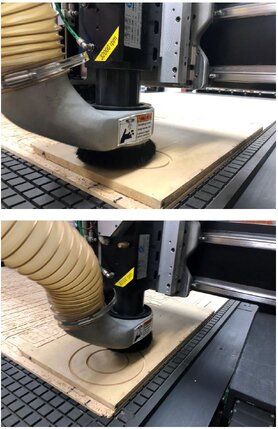
This picture show us how the machine manages its tools, it can hold 6 differents types and use them in the middle of a process, and it also uses a vacuum to extract all wood waste to keep clean all our workplace.
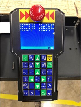
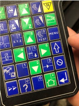
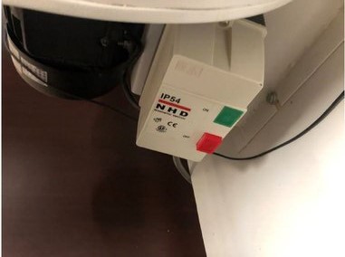
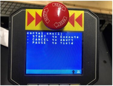
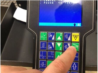
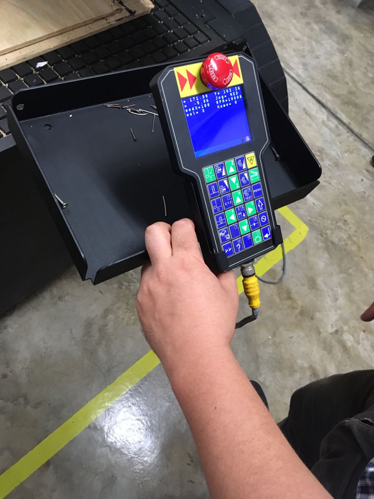
Finally, here is the machine control. It's funny, instead of name on buttons it has picture which represent the actions and mostly could be intuitively reconized. As a small example I tell you the yellow with a traffic signal button means stop the process, NOT cancel.
This last picture was a cartographic map replicated for a minning company made at ULima Fab Lab grouping some triplay's layers.
Getting some practice and knowledge
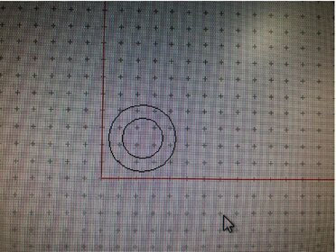
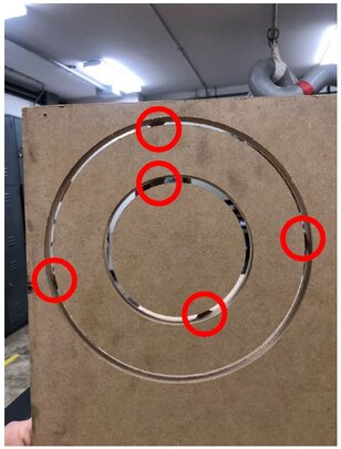
At this part I will show you the process of milling with pictures. Was a simple project which involved to circules one inside the other to test "Bridge's Function".
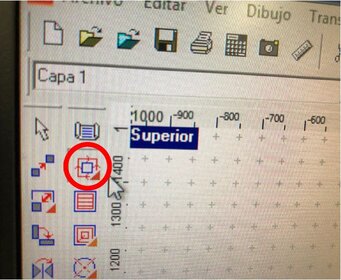
First we have to design anything and select the next icon.
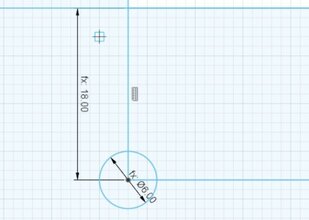
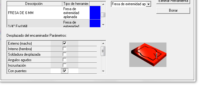
Now we have to set some parameters like the material depth and the maximun speed of the tool which as a recommendation is 18 000 RPM for all materials we have at stock.
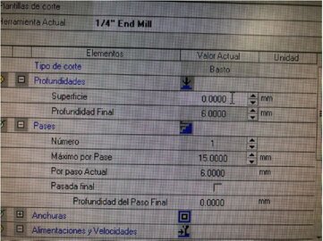
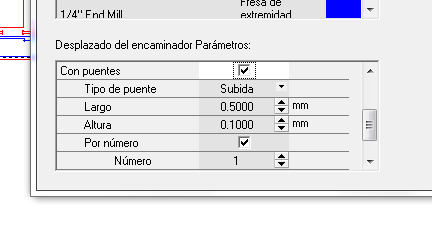
Here is the window which is important to consider if we will need to use bridges.
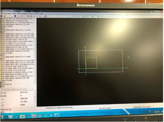
Then we have to export our project as a G-Code clicking in this icon and later check the code to be clear if something is wrong inside it, a small advice don't pay attention al code just specific parts as where machine will take the position as 0, 0, 0, or which tool it will use.
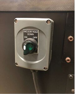
Time to go to the machine. First we have to start the machine and vacuum clicking the next buttons. The extraction system starts near the tool, goes up to the roof and finish at some sacks
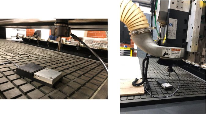
Now it's time to calibrate the Z-Axis for which we have to use the next button and an special tool, as some weeks ago when I was using the milling machine to create my boards.

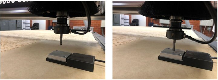
Then when we upload the proyect this message will appear, we have to go to the machine control and press "Play" button. And the machine will start the process.
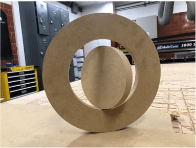
Finally we will have this product. To finish we have to clean all bridge and its wastes.
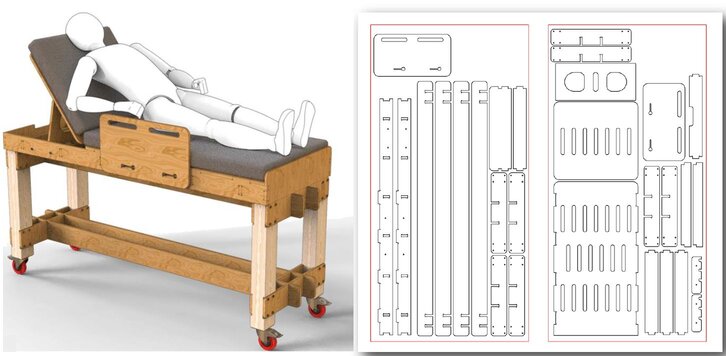
At last, here is a picture of a project made by my Fab Lab for this pandemic situation. And here is the link if you want to read the articule, it's in Spanish.
Designing my Desk
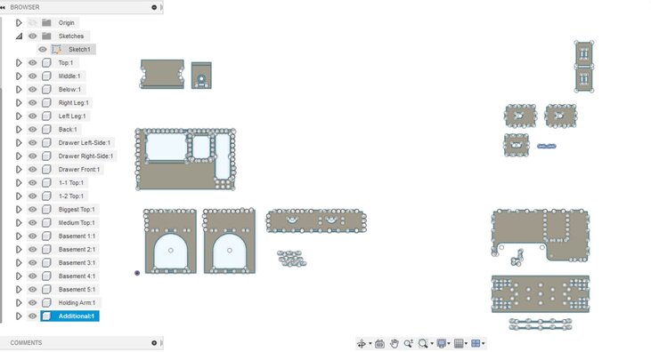
As I specified at top of this page I wanted to design my own desk because I needed it. So first I have to create the plan.
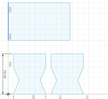
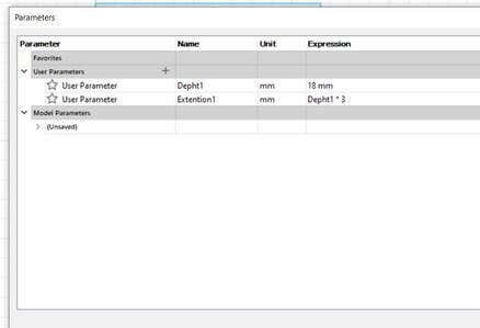
As an additional I decided to use some knowledge learnt at week 3 which was use parameters as you can see.
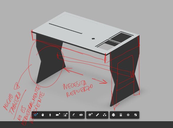
Here my first try
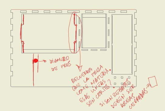
And here comes the observations that it had. Gallery 1:
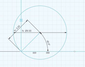
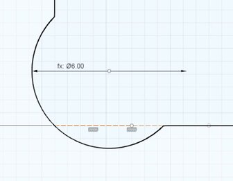
Second I have to use the "T-Bone" for every internal corner which can help when I have to assembly all pieces, I used the diameter of the tool used which is 6 mm. As an advice I use the next method which allow a great performance of the process.
Third, to make easier to design every piece of my project I created a pattern which can help me to locate and decide the shape of the union. At last, for some cases as some simple squares of shapes I did the T-Bones manually.
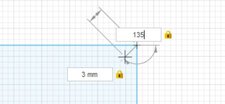
Finally, to check my design and its estimated final shape I extruded and assemblied it. Additional I took a screenshot of all parameters I used.
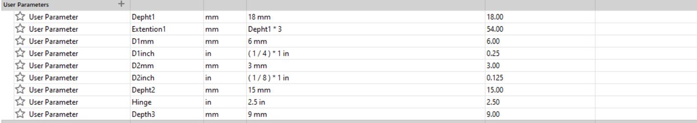
Gallery 2:
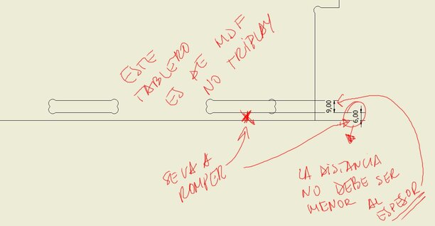
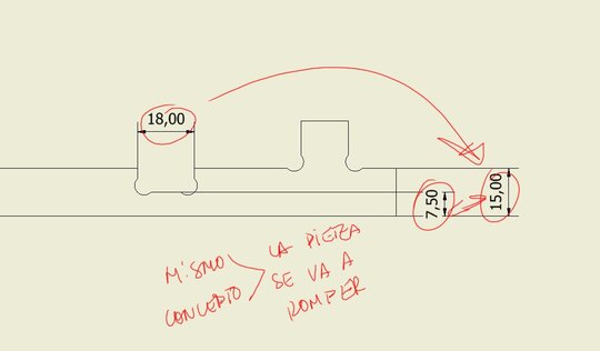
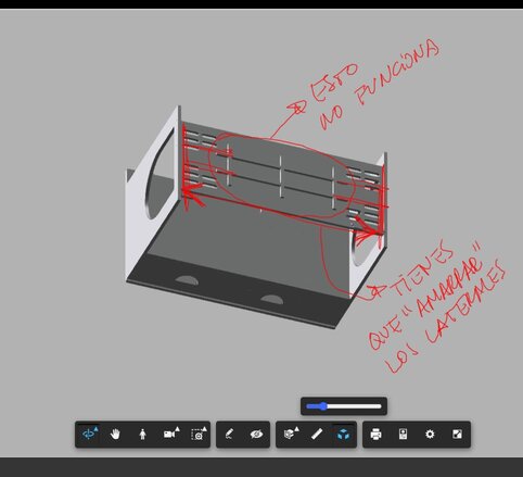
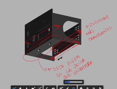
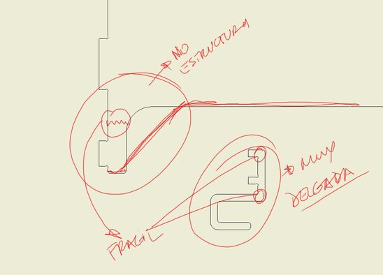
Note: I was receiving support and advices by a profesional designer who was giving me information about the real distribution of forces, and how the structures woud get weak as you could see in some of my pictures.
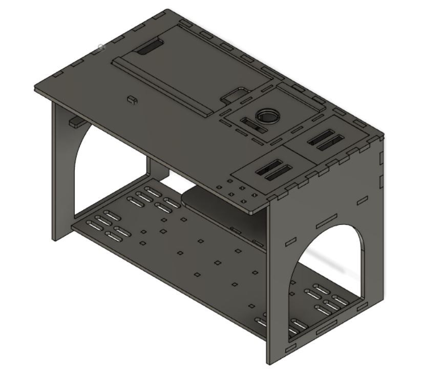
Finishing and Processing my Desk
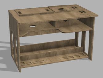
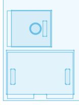
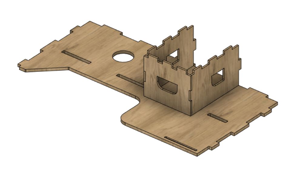
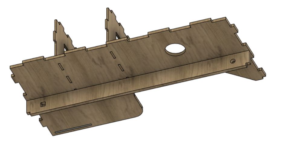
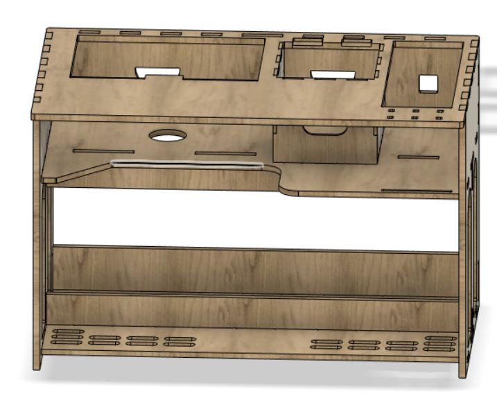
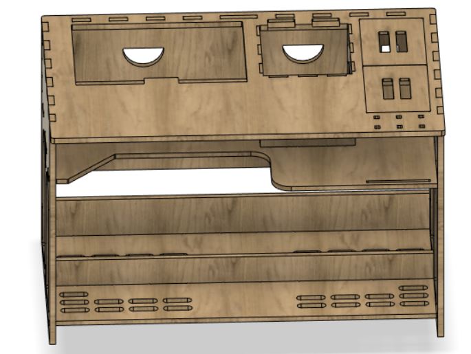
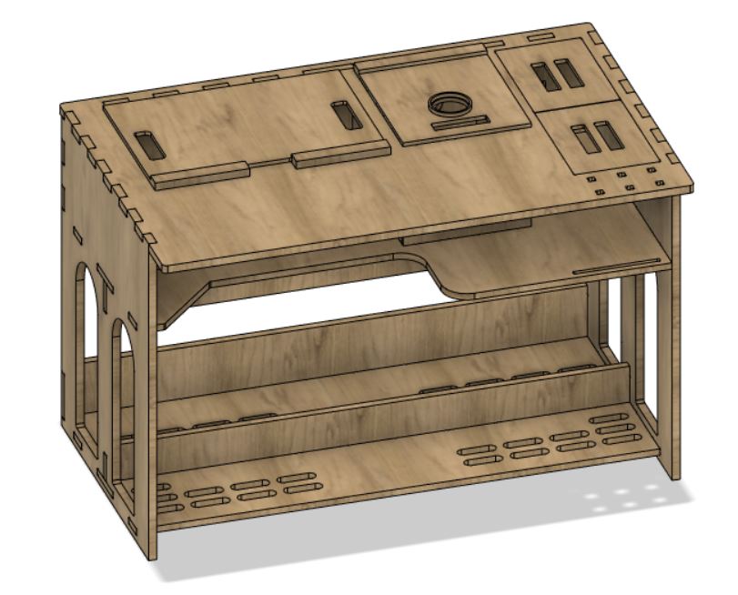
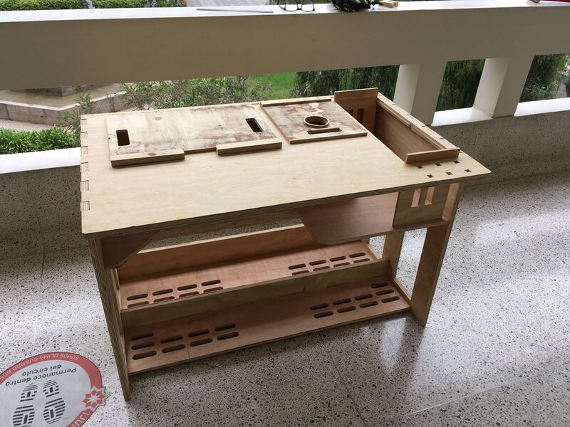
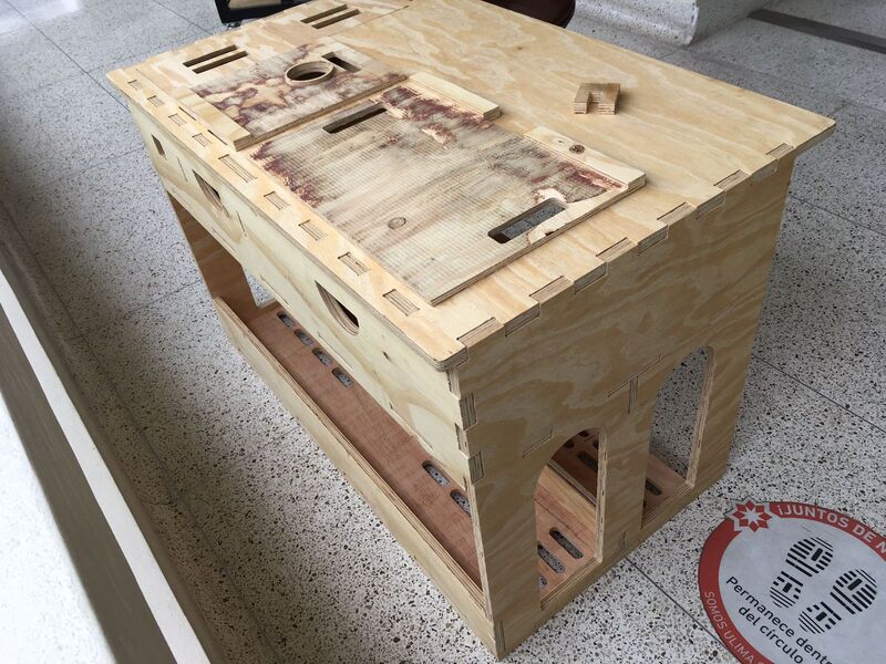
Having considered those advices I finally designed my desk. I'm very satisfied with the result. Let's take a look.
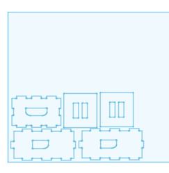
Is highly recommended to group all pieces to be efficient when we will use the MultiCam. That means less waste and cost.
Here are the 9mm parts.
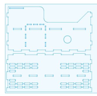
Now comes 15mm parts.
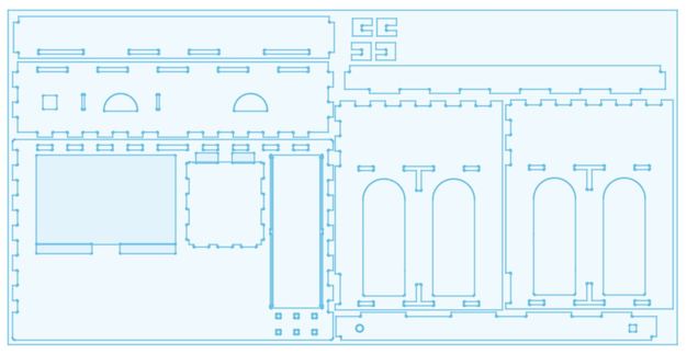
Finally, 18mm parts. Some of these have 2.5D process.
Now it's time to "drive" the machine. First we have to create the G-Code at EnRoute software.
This is how its interface looks.
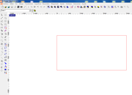
Time to start.
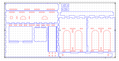
1st We have to import our files. Then selecting al pieces we have to do a right-click an select "Group" option.
That's how it will look.
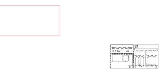
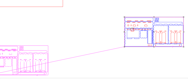
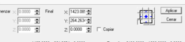
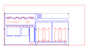
2nd We have to move all pieces to software origin. We have to select the next icon and locate introducing the values in the boxes to finally accept and close.
![]()
The boxes are below the interface as you can see next
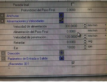
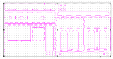
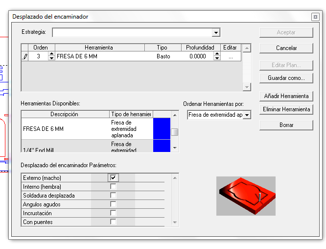
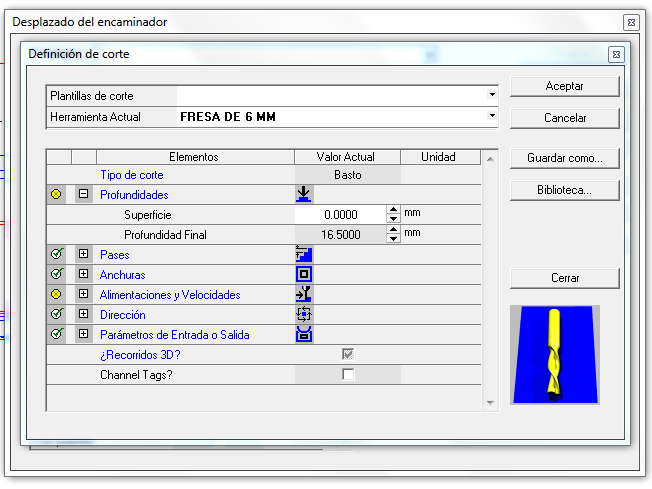
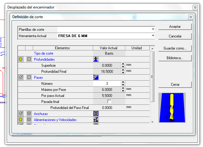
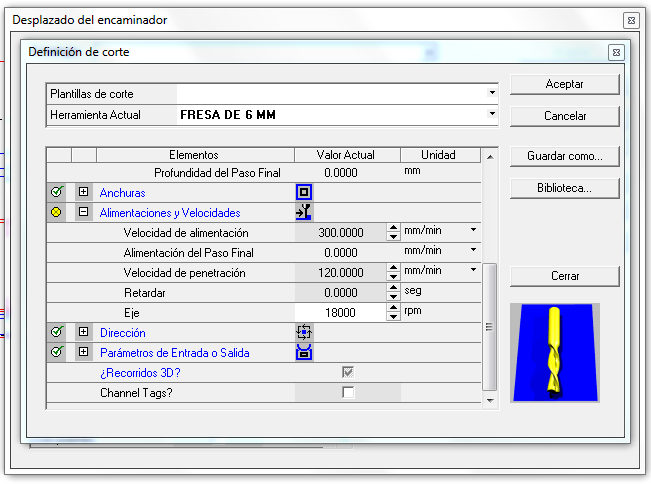
3rd Now is time to set the cutting parameters clicking at next icon and filling all important parameters with which are used by your machine.
![]()
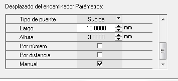
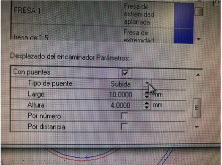
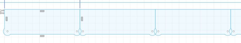
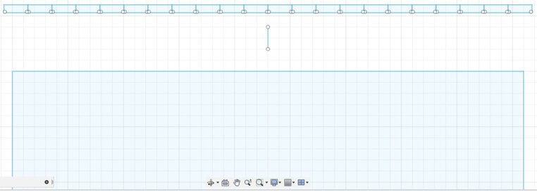
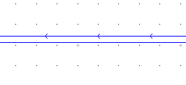
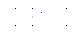
4th I selected the manual option for the bridges. You can easly locate those clicking on the routes as is showed in next pictures.
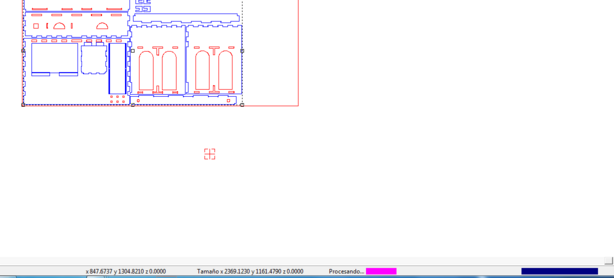
These lines with arrow are the paths where we can put manually bridges.
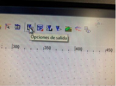
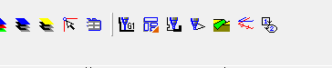
5th We have to export the G-Code clicking at "G1" icon. Then select "By Layers" and "To Files".
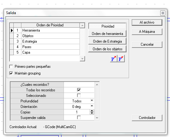
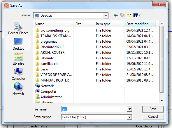
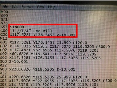
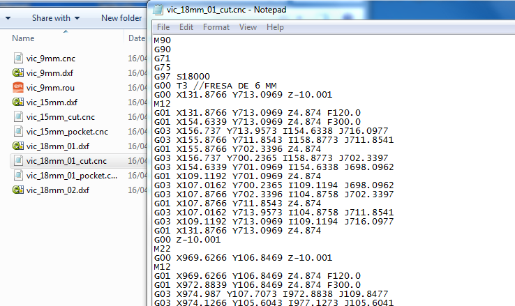
As an important part we have to check the G-Code. In my was wrongly defined other tool and i changed to "T3" which I will used.
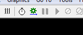
6th We have to open the "Job Console" which sends the file to the machine clicking the green screw.
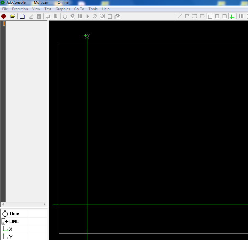
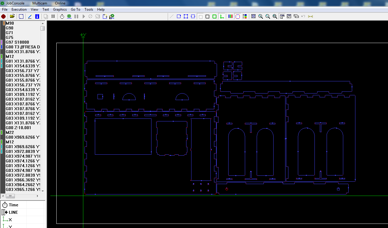
Before we continue we have to set the material on the machine and set the Z maximun depth using the tool.
Note: You might need to change yours perspective.
Then we have to click the "Play" button to start the process.
15 mm process
18 mm process
2.5D process
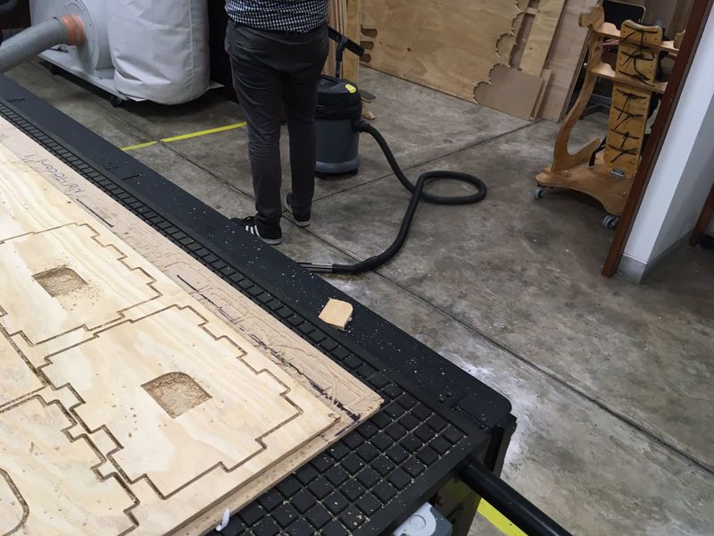
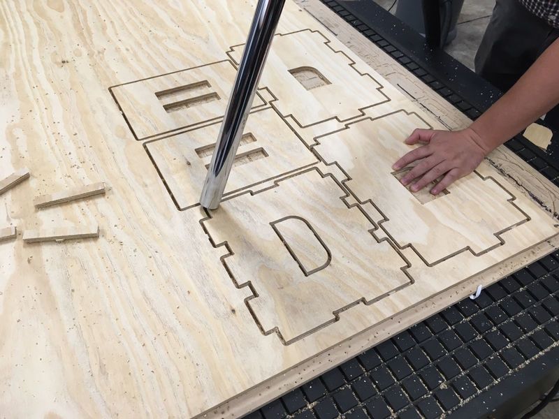
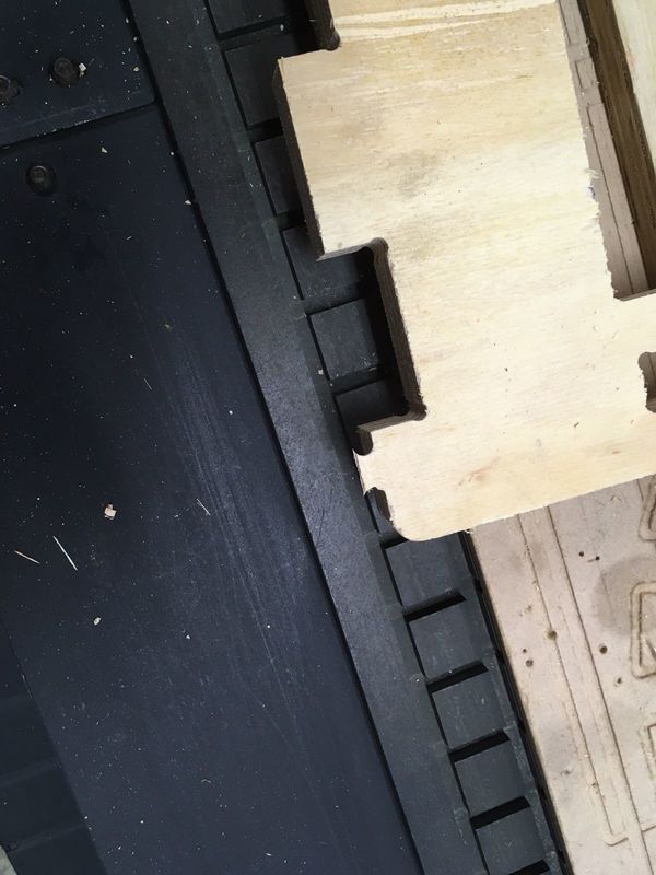
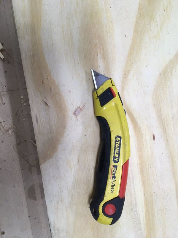
Now we have to clean using a vaccum, retire every piece and clean the bridge's waste, I used a cutter.
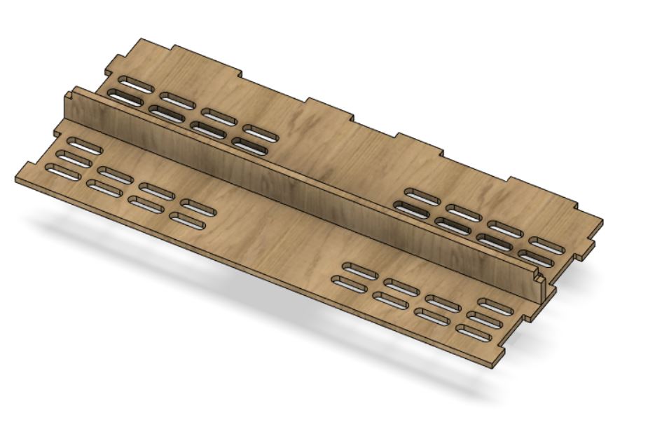
Tutorial: How to assembly
First

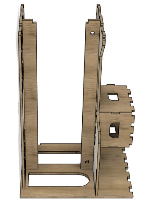
Second
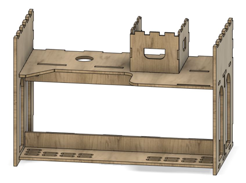
Third
Fourth
Fifth
Sixth
Seventh
Eighth
Ninth
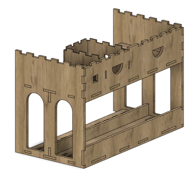
Congratulations! You have a beautiful desk.
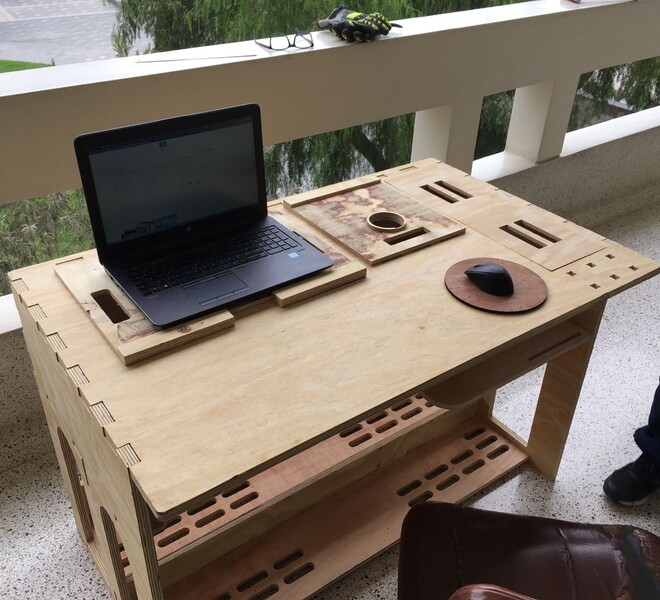
Here it is!
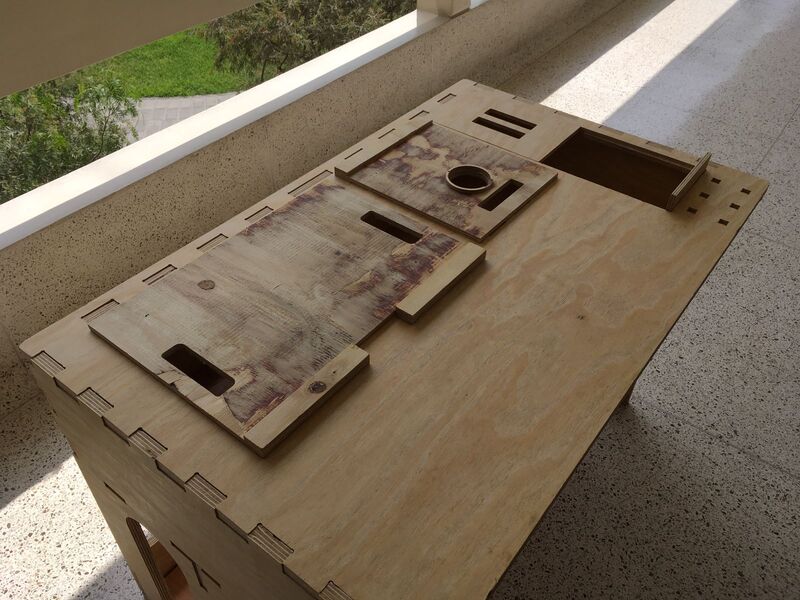
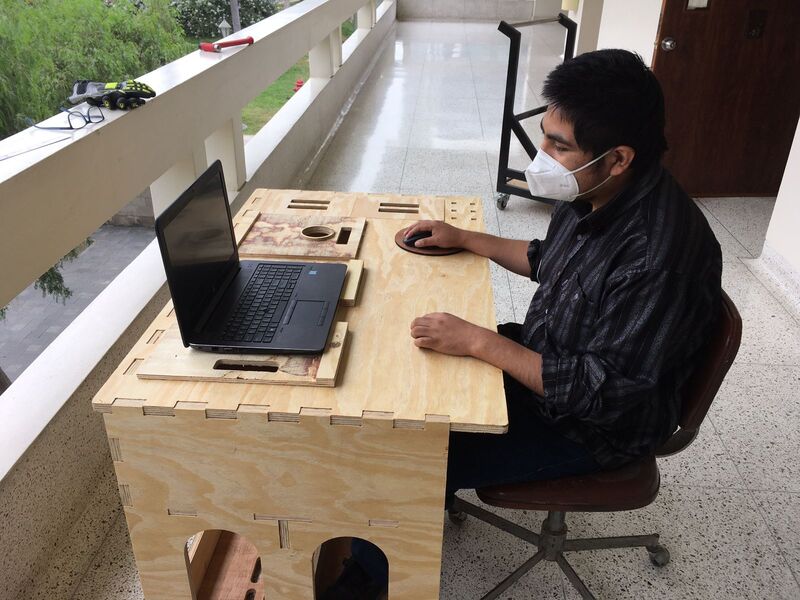
And here is Ronald, who is part of this Fab Lab, testing the performance.
Special thanks to Luis Sierra who is part of ULima Fab Lab and was supporting and assesoring me in this assignment at this pandemic situation.