16. Applications and Implications
Objectives
- Propose a final project masterpiece that integrates the range of units covered.
What will it do?
My project is in the scope of my Ph.D. subject.
I intend to measure the activity, pressure, and deformation of a human bladder to detect micturition issues.
In particular, a “neurogenic” bladder defines bladder and sphincter dysfunctions related to a neurological disease or a condition such as a spinal cord injury (SCI). Clinical manifestations include detrusor (the main muscle of the bladder) overactivity leading to incontinence and detrusor sphincter dyssynergia which can result in irreversible kidney damage.
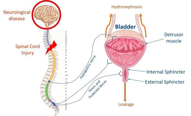
The idea is therefore to be able to monitor and predict the bladder activity as well as rising intravesical pressure as it would allow new and innovative management techniques to improve patient’s quality of life as well as psychological and physical well-being.
The bladder phantom
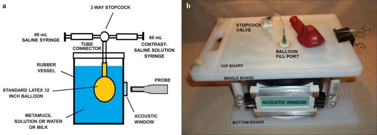
The first step in such a project is to test the monitoring device on a phantom, i.e. a model that shares similar properties with the studied organ.
The state-of-the-art bladder phantom is, still today, a rubber balloon. It is, for many reasons, not a good model of the bladder.
My objective is, therefore, to provide a new bladder phantom, able to simulate the bladder filling, along with its mechanical properties and detrusor contractions. Then, I will use a range of sensors to measure phantom activity.
Who has done what beforehand?
Not many people tried to model the bladder As said before, the current state-ot-the-art model is a rubber balloon.
Some models are more advanced but are especially dedicated to teaching surgery or endoscopic procedures and are not a good model of the bladder activity, pressure, or filling properties (Shellikeri, S., Back, S. J., Poznick, L., & Darge, K. (2018). A Low-Cost, Durable and Re-Usable Bladder Phantom: Teaching Intravesical Ultrasound Contrast Administration. Ultrasound in Medicine and Biology, 44(8), 1918–1926. https://doi.org/10.1016/j.ultrasmedbio.2018.04.008)
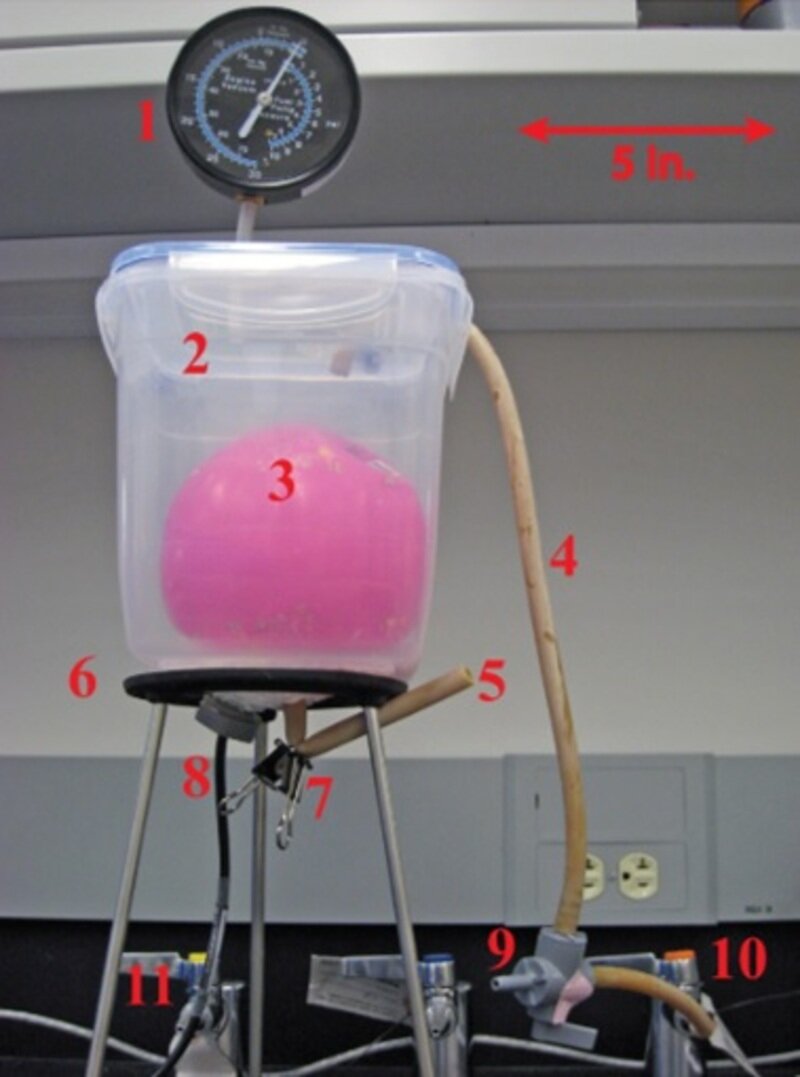
Other people added a very simple pressure chamber around the rubber balloon to model the detrusor pressure (Weaver, J. N., Alspaugh, J. C., & Behkam, B. (2010). Toward a minimally invasive bladder pressure monitoring system: Model bladder for in vitro testing. 2010 3rd IEEE RAS and EMBS International Conference on Biomedical Robotics and Biomechatronics, BioRob 2010, 638–643. https://doi.org/10.1109/BIOROB.2010.5625981)
Finally, I was inspired by other people making pressure regulation system like Gilles Decroly.
What will you design?
I will design a few different things:
- A bladder phantom made of silicone with similar mechanical properties to a real bladder. This includes making a 3D-printed mold in two parts: an outer mold in PLA and an inner mold in water-soluble PVA, before pouring the silicone mix.
- An automatic bladder filling system. This system will include peristaltic pumps to pump water inside the phantom at a steady, controlled rate.
- An hermetic pressure chamber made of plexiglass whose pressure can be controlled with a vacuum pump.
- Various sensors to measure the intravesical pressure, the chamber pressure, and the phantom strain. Additional sensors could be temperature and humidity.
- Interface and control elements. I will make a control box with an LCD resistive touchscreen and various pushbuttons and switches to control the pump flow rates and pressure as well as monitor the various measurements. The whole kit will be controlled using an ESP-32.
What materials and components will be used, where will they come from and how much will they cost?
Sensor requirements
The strain gauge used will be a commercially available one that will be encapsulated in silicone before being anchored on the phantom.
The phantom pressure sensor can reach a maximum of 200cmH2O (196mBar, 196kPa, 2.84psi) in addition to the external pressure. Note that since the sensor will be inside the pressurized chamber, it cannot be a gauge or differential sensor, it needs to be an absolute one (referred to as a calibrated vacuum). Also, it must be waterproof. Based on these requirements, I chose the MS5837. Note that I will have 2 of them on the same I²C channel so I will need an I²C multiplexer. For the chamber pressure measurement, the maximum pressure can reach 2atm so I will use a slightly larger range sensor, the MPRLS0030.
The other requirements and choices will be explained in the full project documentation.
Bill of materials
Here is the list of the various materials and components that I am going to use for each part of the project.
What parts and systems will be made and what processes will be used?
A said before, most of the parts will be handmade!
-
For the phantom bladder, I will mold it with silicone, using a vacuum bell. I intend to print the molds using PLA and PVA but the outer mold could be improved if made in Teflon with the CNC. The silicone mix is chosen for its mechanical properties. Additional silicone fibers will be made in Sorta Clear 40 to model the detrusor muscular fibers around the bladder. These fibers should be highly modular and practical so that I can easily add or remove some, change their positions, … Additionally, it would be a nice improvement to be able to start from a 3D scan of a real bladder to make the mold.
-
For the pressure chamber, I will cut my PMMA sheets with the laser cutter and glue them strongly with the acrifix 192. If the system is fast enough, one could imagine triggering a sudden increase in pressure to model contractions. This would require a solenoid valve and a pressure tank which will increase the cost and the complexity. 5 PMMA sheets will be glued together and a mainboard in wood at the bottom with some silicone sealing will hold everything together. Water tanks for the bladder filling will be placed near the chamber as well.
-
The electronics boards will be mainly made by chemical etching and assembled using SMD components.
-
The motors and pumps will be controlled using an L293D motor driver.
-
The interface with the touchscreen will be SPI or parallel depending on the refresh rate.
-
The pressure sensors will be connected through I²C.
-
An amplifier and filtering circuit for the strain gauge will be handmade.
-
Fluidics and electronics wires will enter the chamber through a hermetic entrance and a hermetic D-sub connector. Fluidic connectors and tubes will be refurbished from various other projects.
As a summary, here is a very simplified block diagram of the system:

What questions need to be answered and how the project will be evaluated?
I want to be able to continuously fill the phantom with a flow rate between 1 and 30ml/min while monitoring its pressure and strain using the various sensors. I want to control the flow rate entering the bladder as well as the pressure inside the chamber. The sensors should send measurements every 33ms to the ESP32 and I should be able to store the measurements on my computer in a CSV file.
This project will be a success if we can successfully observe and measure the increase or decrease in pressure and strain during the filling and emptying process for multiple flowrates, chamber pressures, and silicone mix for the phantoms as well as the detrusor fibers.
The project could always be improved obviously by adding more sensors, more pressure, more control, …