Skip to content

13. Networking and Communications

Objectives

  • Group Assignment: Send a message between two projects.
  • Design, build, and connect wired or wireless node(s) with network or bus addresses

Group assignment

During Electronics production week, Jason and I already connected two of our own boards and communicated between them using UART. We also made more progress on our group assignment page.

logo text
Our boards connected
logo text
Communication using UART and messages displayed through the Serial USB monitor in Arduino

Making a network board

For my network, I wanted to make a board that is able to communicate using a single master on the bus and a lot of slaves. I want all the communication to happen in “human-readable format”, meaning using ASCII characters mainly. Also, for simplicity purposes, I intend to use an asynchronous communication protocol and a single data wire. Obviously, I will need addresses to choose which slave I communicate to, and I will have framing data (start of frame and end of frame).

I chose to use ATSAMD11C as the main microcontroller. The nodes can be anything, but in order to only make a single board, they will be SAMD11C as well, but it could work with almost any controller like an ATTiny for example.

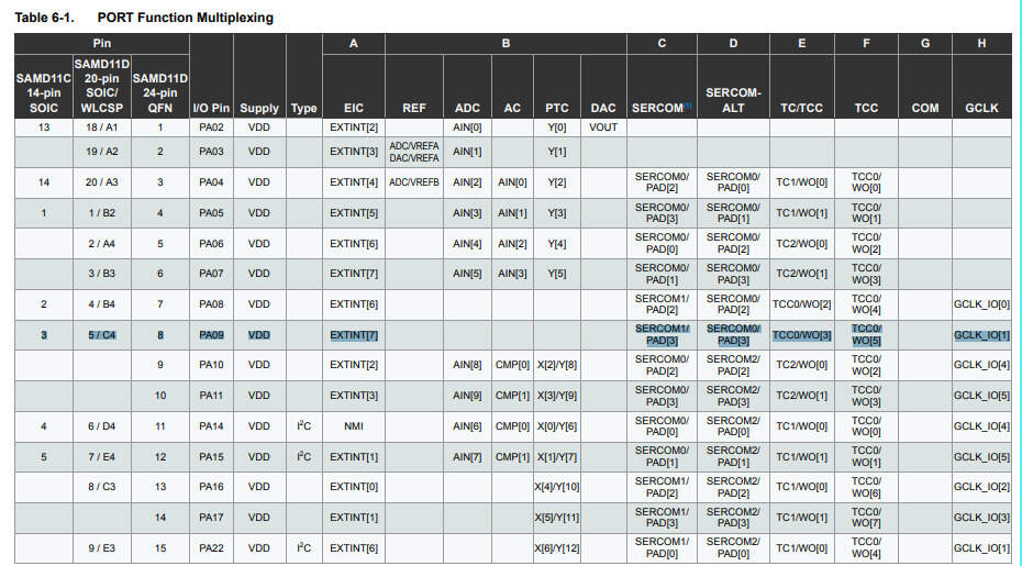
The idea is to use the UART protocol (RX and TX pins) but to make it a full network bus, I’ll share the RX between all the nodes, and the TXs will be connected with the RXs through a diode at each node, in order for them to be able to pull the signal low when they want to send a message. I end up with a single wire: RX between all the nodes (and a shared GND obviously). Note that each board can be powered separately but they can also share the power line.

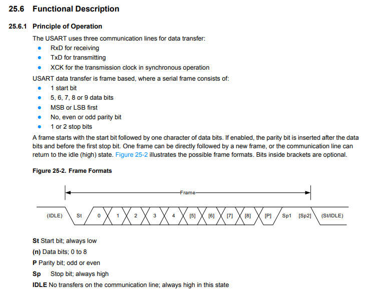
The good news is also that, as indicated in the datasheet of the SAMD11C, the UART protocol is already completely implemented, features start and stop bit, parity bit and the idle state is high. So, by default, TX will not make the diode conducting, which is exactly what we want.

logo text
From SAMD11 datasheet

The design

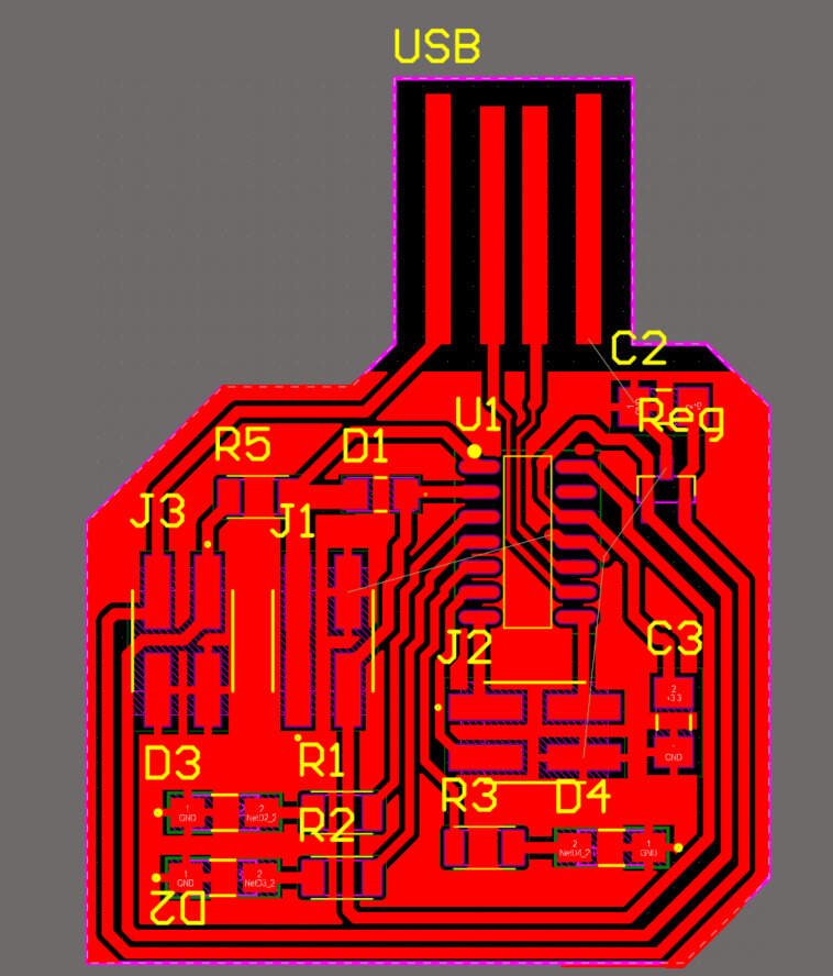
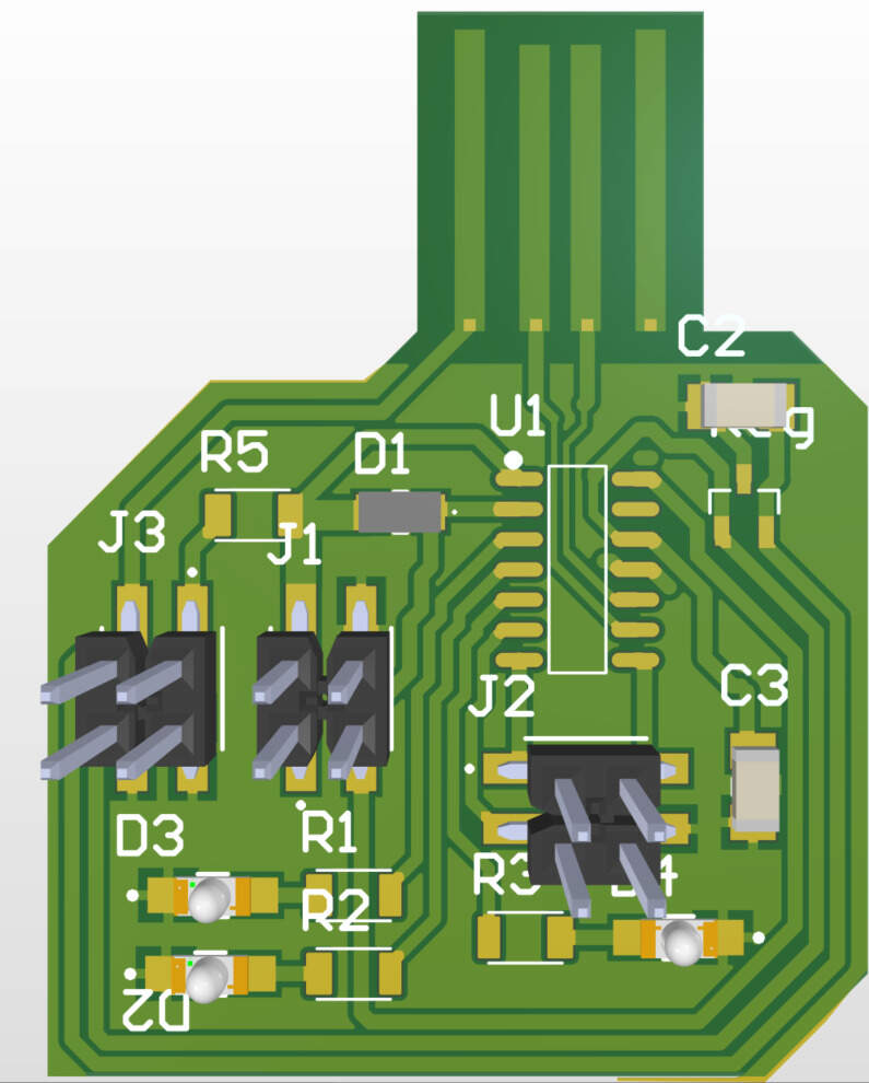
The design itself is relatively straightforward, here are the main components:

  • An ATSAMD11C
  • A 3.3V regulator
  • A USB copper connector
  • A pull-up resistor on RX (for the master only)
  • A diode between RX and TX (cathode on TX)
  • A few LEDs and current limiting resistors connected to GPIOs so that I have a visual feedback of the communication
  • A 4x connector for Programmation through SWD
  • Connectors for RX, TX, 3.3V, 5V, GND.

The Altium schematic is shown below and is available in the design files.

logo text
Network board schematic

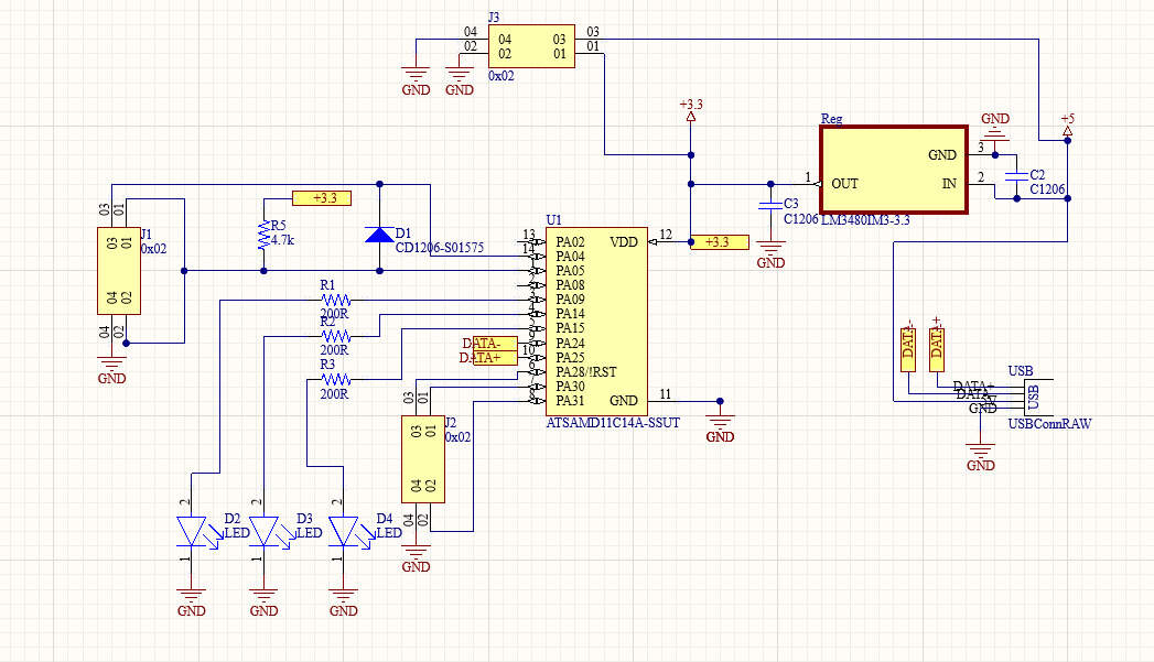
I connected everything in Altium, added a ground plane and my board is basically ready. In practice, there is no connection between two ground planes so I’ll have to a add small wire to link them as it would be very space-inefficient to try to connect them with traces or to use a jumper.
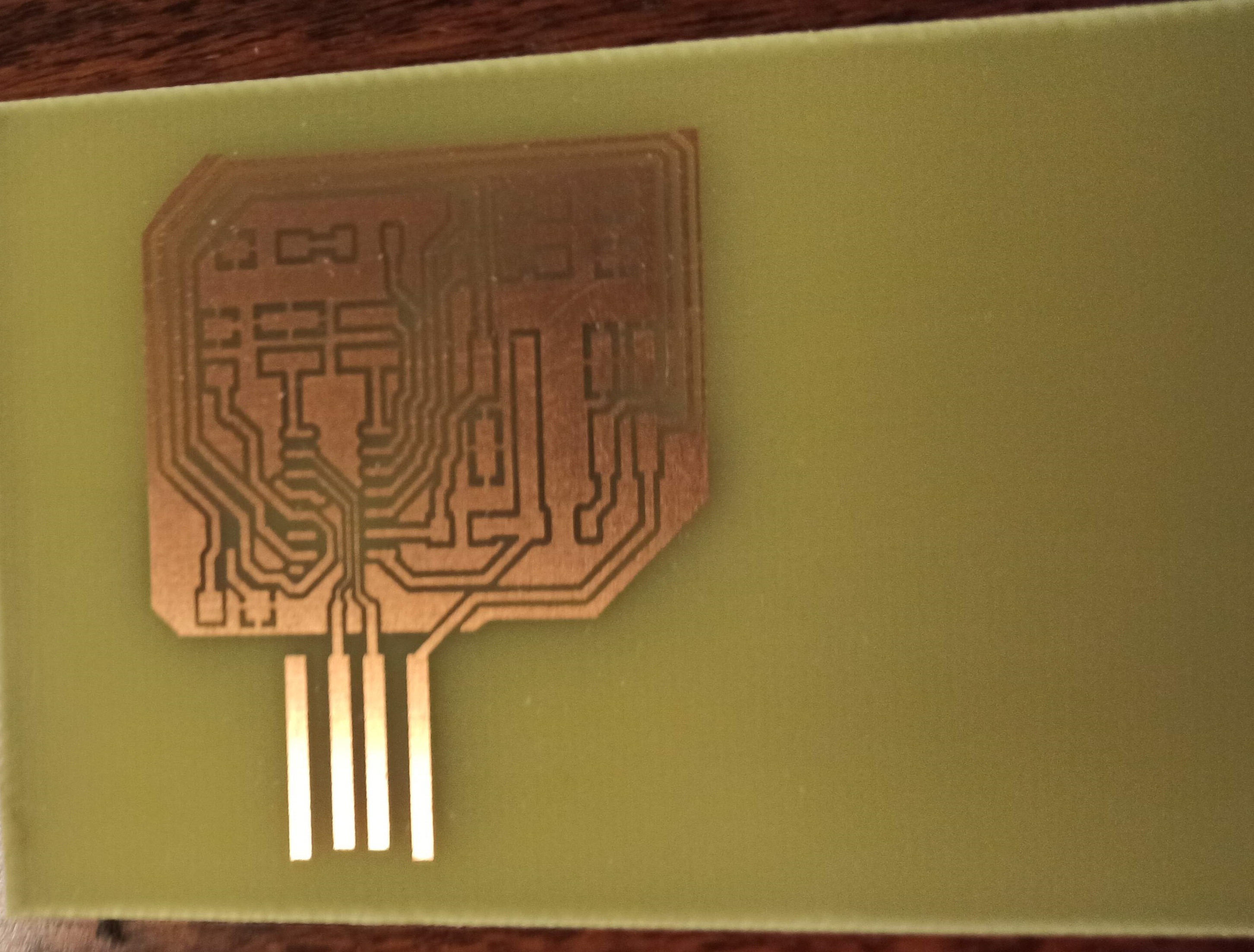
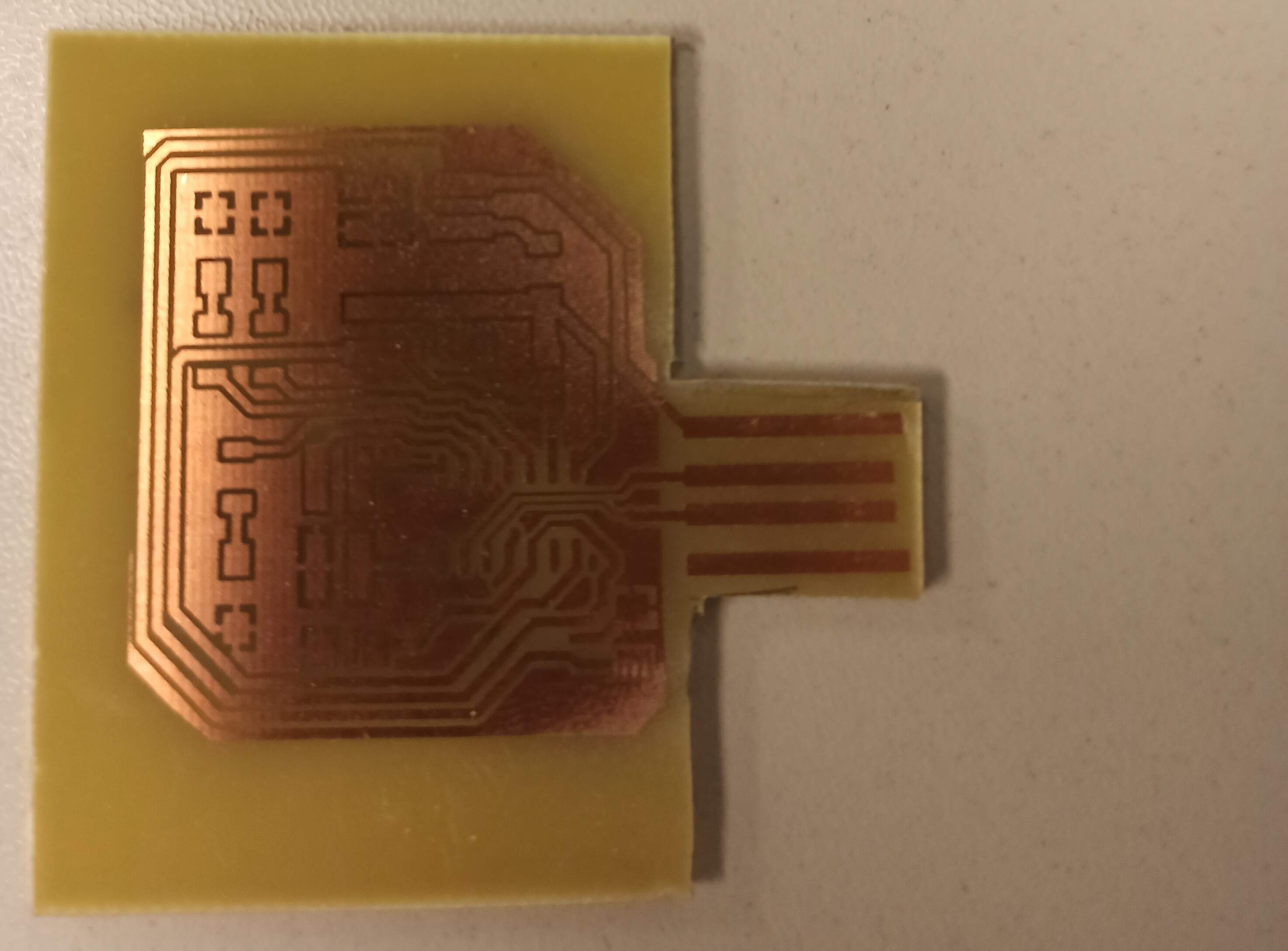
logo text
Altium PCB
logo text
3D view

Making the board

I had some trouble with the CNC engraver and the copper plates that were not perfectly plane so I ended up using chemical etching to make the board. It went flawlessly and the result is extremely good.

logo text
After chemical etching

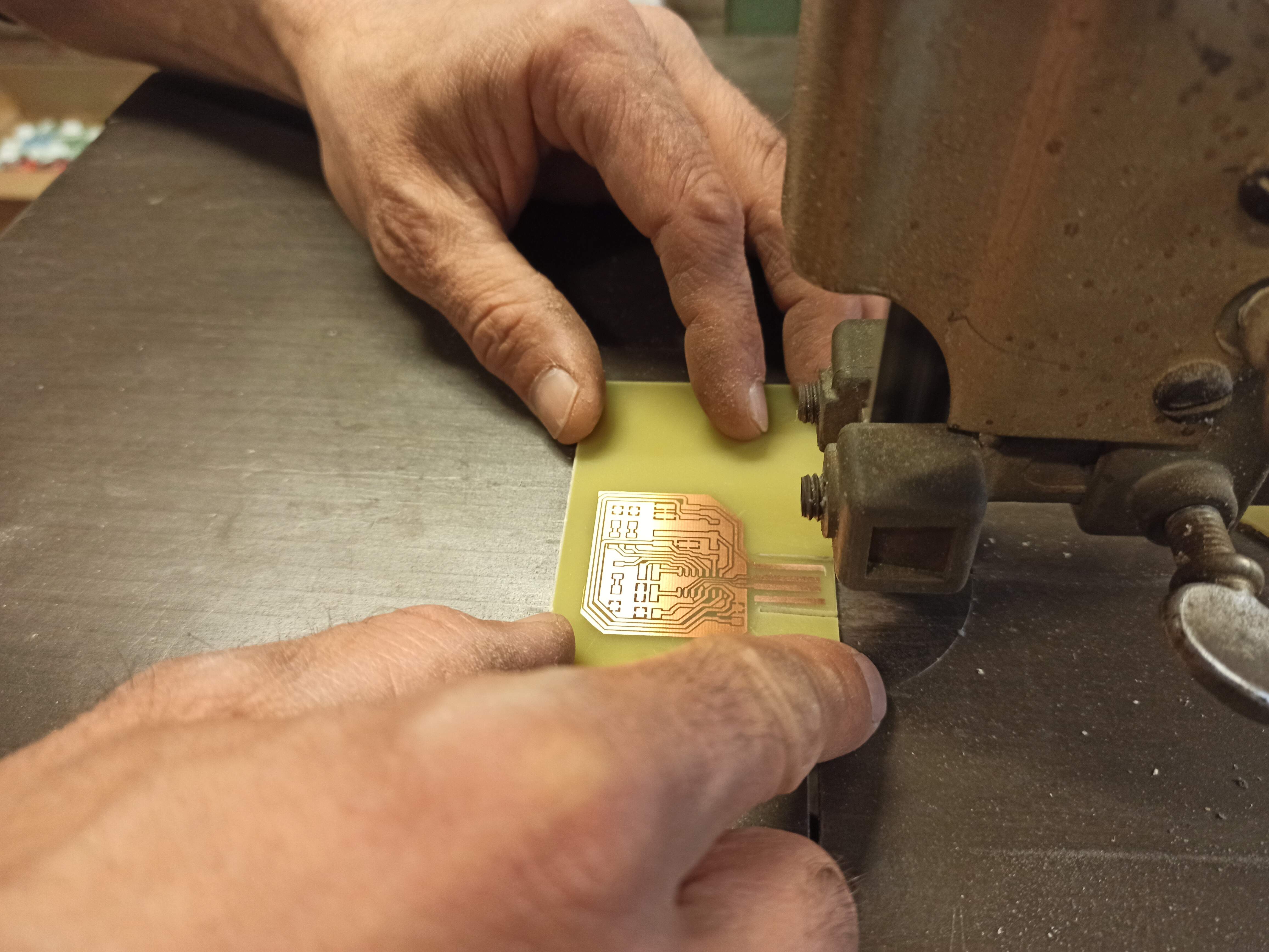
Obviously, I still need to cut it to make the right shape then, especially for the USB connector so I used a rolling saw.

logo text
Cutting the outline
logo text
Cut board

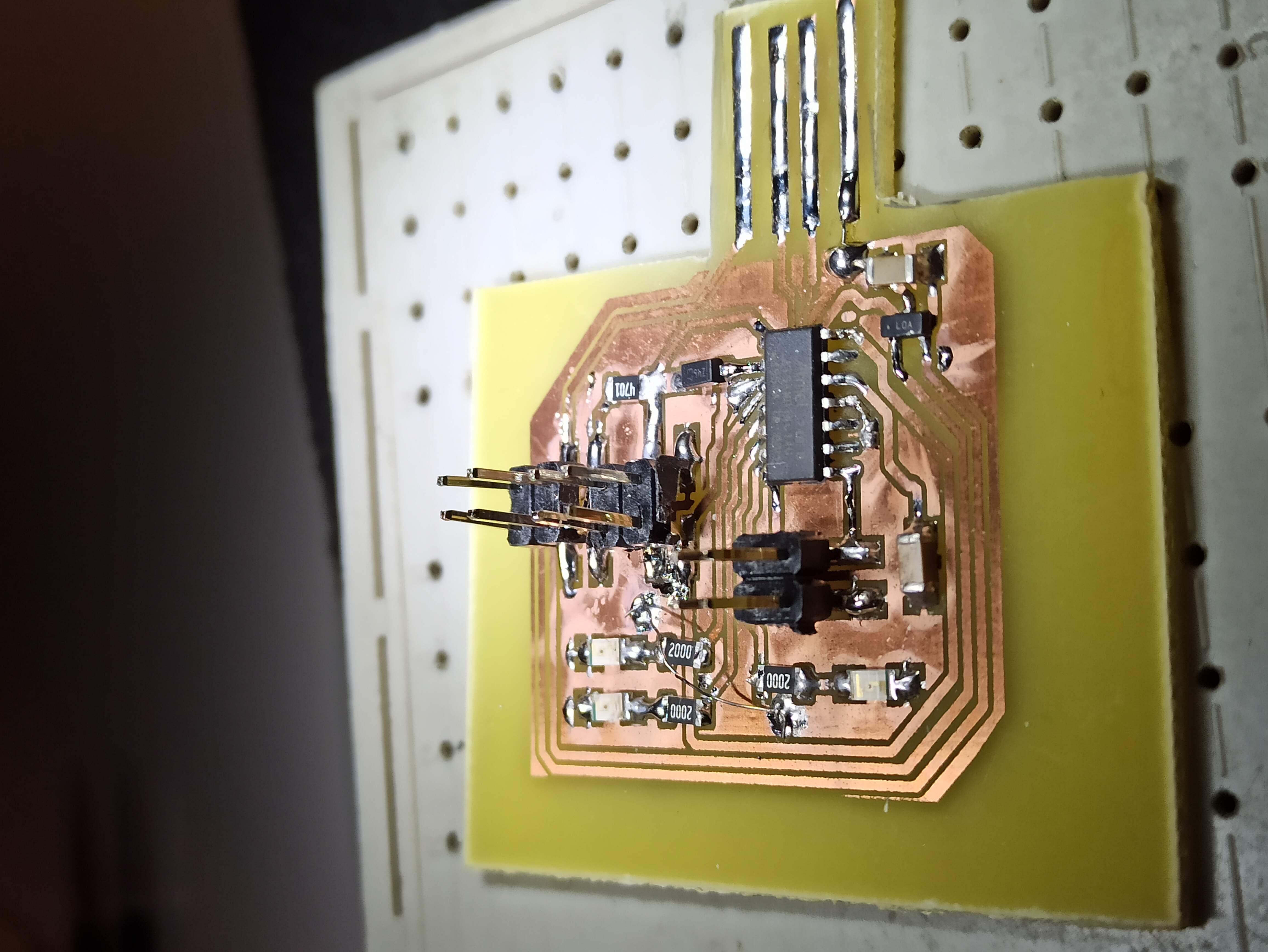
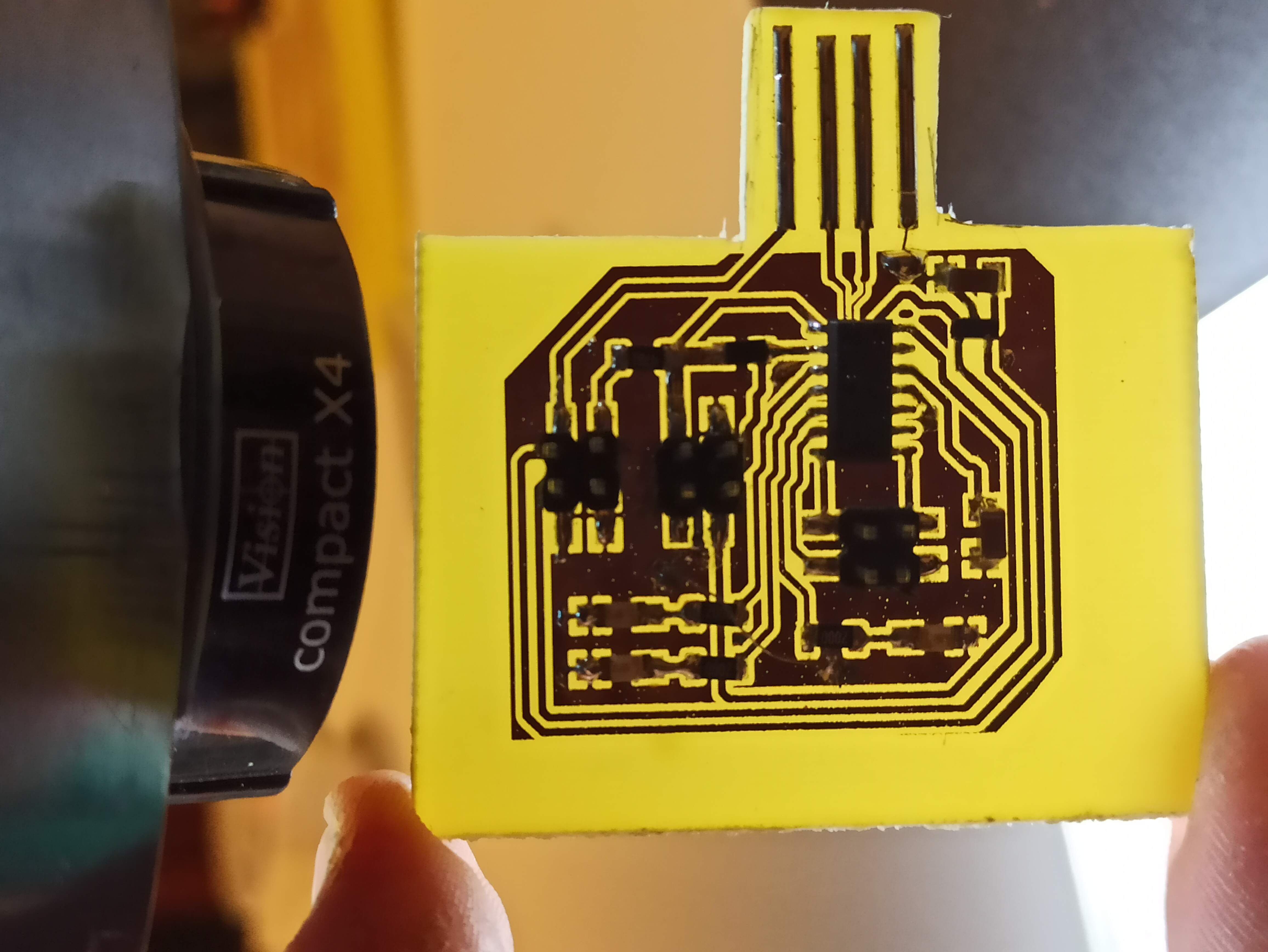
Time to solder everything, nothing complicated, especially with the magnifying glass, and I made sure to well tin the USB connector.

logo text
Cut board
logo text
Cut board

Programming the SAMD

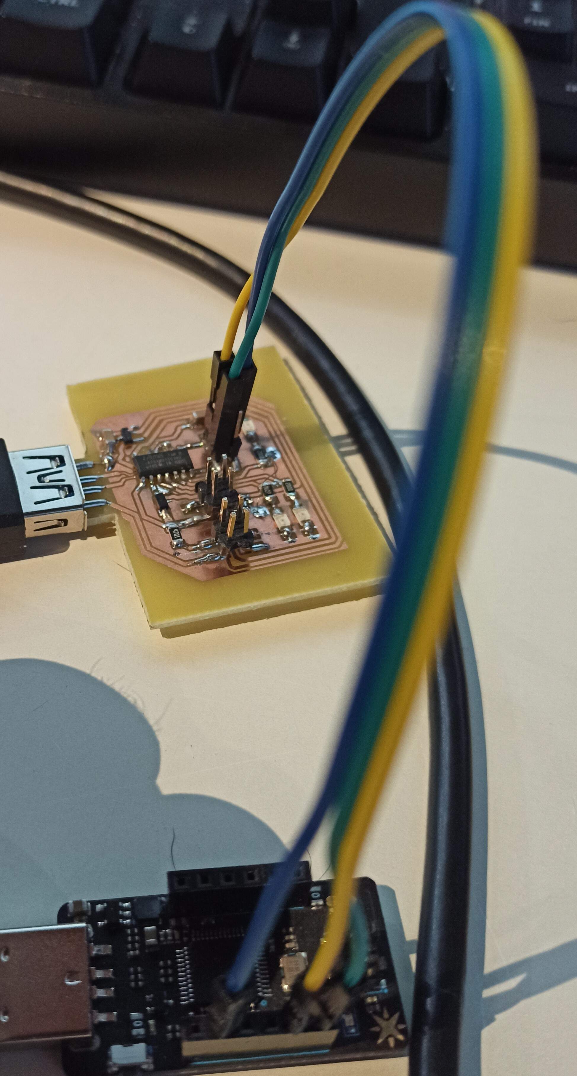
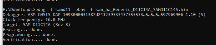
To program the SAMD, I intended to use my own programmer but I think it did not hold up together over time as copper turned green and I wasn’t able to program my new board. So I had to rely on a commercial CMSIS-DAP programmer. It worked perfectly, I only needed to connect SWDIO, SWCLK, and GND to my board.

logo text
Connecting the board and the programmer

I loaded the sam_ba bootloader so I can use the Arduino IDE to program my board, which will initially ease up the process.

logo text
Succesful progamming

I started by checking that everything on my board worked correctly by lighting up the LEDs. Good thing I did because one was not perfectly soldered and wouldn’t light up reliably so I needed to correct that soldering a bit!

The third LED does not blink

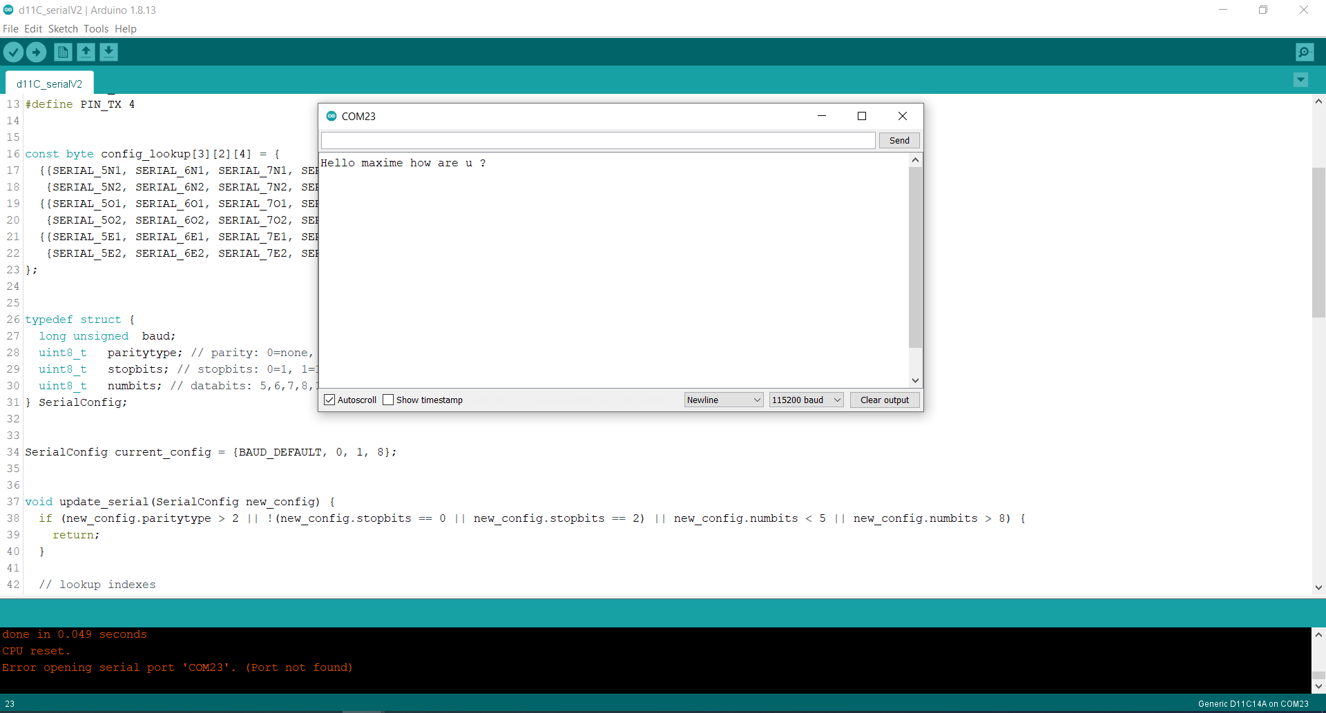
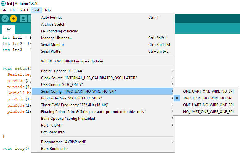
I then tried to send data over the UART and directly read it. Note that using the ArduinoSAMDCore for Mattairtech, you can use the RX2, TX2 Serial which is the second UART channel on the SAMD by using “Serial2” command. The USB, if selected in the config, will be available on “Serial” or “SerialUSB”. However, there is currently a bug (not yet reported ?) that makes the SerialUSB also communicate on the RX1, TX1 (so UART channel1). One of my LEDs being soldered on the TX1 pin would blink whenever I try to print on the SerialUSB. I tried multiple things to disconnect it (Serial config, using “Serial1.end()”, pinMode, …) but couldn’t make it happen.

logo text
SerialConfig
logo text
Pin PA09 is used for SERCOM1 as well

Here is the code to make the LEDs blink and communicate over the bus and reading it back.

 1
 2
 3
 4
 5
 6
 7
 8
 9
10
11
12
13
14
15
16
17
18
19
20
21
22
23
24
25
26
27
28
29
30
31
32
33
34
35
36
37
38
39
40
41
42
43
int led1 = 9;
int led2= 14;
int led3 = 15;


void setup() {
  Serial.begin(9600);
  pinMode(5, INPUT);
  pinMode(4, OUTPUT);
  Serial2.begin(9600);
  pinMode(led1, OUTPUT);
  pinMode(led2, OUTPUT);
  pinMode(led3, OUTPUT);


}

void loop() {
  Serial2.println("test");
  if(Serial2.available()){
    Serial.print("received : ");
    while(Serial2.available()){
    Serial.print((char)Serial2.read());  
    }
    Serial.println("");

  }

  Serial.println("a");
  digitalWrite(led1, HIGH);
  delay(300);
  digitalWrite(led2, HIGH);
  delay(300);
  digitalWrite(led3, HIGH);
  delay(300);
  digitalWrite(led1, LOW);  
  delay(300);
  digitalWrite(led2, LOW);
  delay(300);
  digitalWrite(led3, LOW);
  delay(300);
}
logo text
I can send an receive a message (on the same board)
logo text
Connecting GND, RX and 3.3V between two boards

Adding some framing

Even though I’m using the UART protocol which already features start bit, stop bit, … I will add “start of frame” and “end of frame” characters in my message to be able to detect the start and the end of a message on the bus.

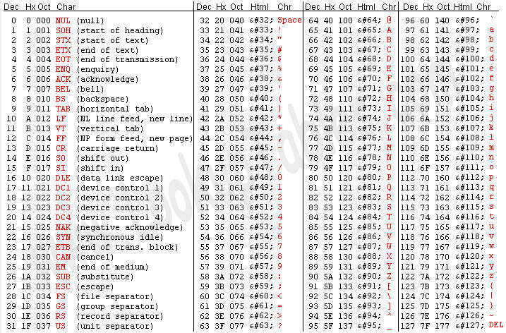
To do so, I chose to use the 0x02 and 0x03 characters which are already set as start of text and end of text in the ASCII encoding.

logo text
ASCII encoding table

In the code, I simply check whether there is data in the Serial2 buffer and if so, I read until I reach the start of a frame. I then check the address and if the message is for this node, I process it, otherwise, I read the buffer until I read the end of the frame before starting the cycle again.

Data format

To communicate order between the master and the nodes, I chose a very simple encoding. Since I only want to switch on or off some LEDs, I use a pair cmd/param. The cmd variable indicates which LED to switch state, and the param variable indicates whether it should be turned on or off. For example, to light up the LED2, I type ‘21’.

The addresses are encoded as alphabetical values. The master being ‘a’ and all the nodes being ‘b’, ‘c’, … up to ‘z’.
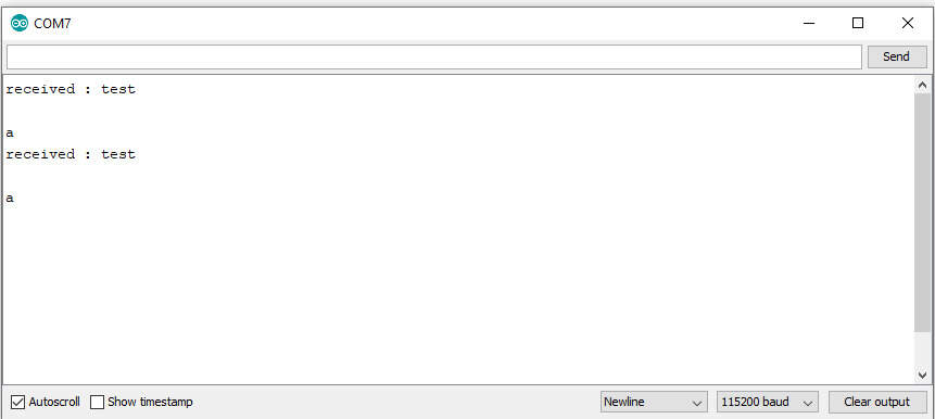
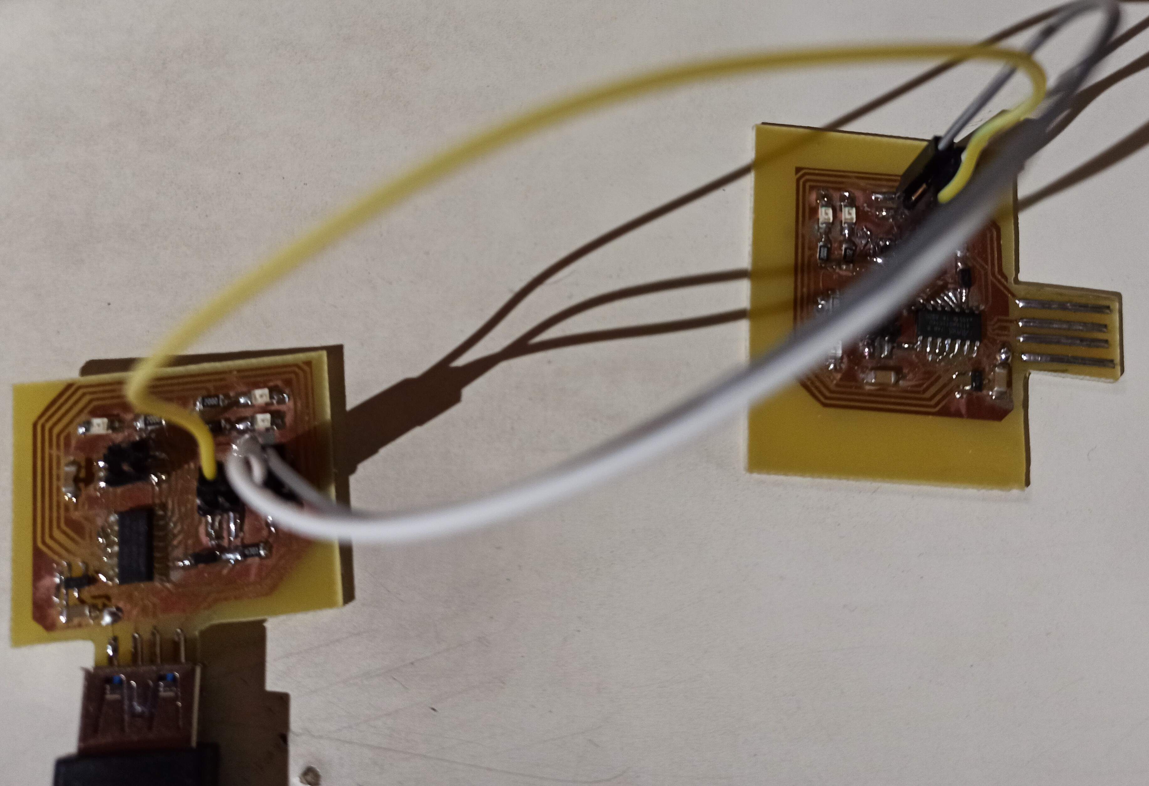
Communicating

Testing this idea proved to be very efficient and I could turn all the LEDs on and off on the slave by sending ‘11’, ‘21’, ‘31’, ‘10’, ‘20’, ‘30’ in a loop. You can also slightly see the green LED blink on the master each time it communicates on the SerialUSB.

Giving order through the SerialUSB

Now that it is working automatically, the final step is to incorporate the possibility to specifically give the order to switch on or off an LED through the SerialUSB terminal. There is however another bug where the Serials will get confused if you try sending data over UART right after reading incoming data on the USB buffer, and it will send ‘0x00’ over the UART. I couldn’t find the exact reason and it seems this bug has not yet been reported. The only solution is to add a small delay (300ms works) between the read of the USB buffer and sending the data over UART.

Here is the final result and the code

This code works for both the master and the slaves. You only need to comment or uncomment the first line.

  1
  2
  3
  4
  5
  6
  7
  8
  9
 10
 11
 12
 13
 14
 15
 16
 17
 18
 19
 20
 21
 22
 23
 24
 25
 26
 27
 28
 29
 30
 31
 32
 33
 34
 35
 36
 37
 38
 39
 40
 41
 42
 43
 44
 45
 46
 47
 48
 49
 50
 51
 52
 53
 54
 55
 56
 57
 58
 59
 60
 61
 62
 63
 64
 65
 66
 67
 68
 69
 70
 71
 72
 73
 74
 75
 76
 77
 78
 79
 80
 81
 82
 83
 84
 85
 86
 87
 88
 89
 90
 91
 92
 93
 94
 95
 96
 97
 98
 99
100
101
102
103
104
105
106
107
108
109
110
111
112
113
114
115
116
117
118
119
120
121
122
123
124
125
126
127
128
129
130
131
132
133
134
135
136
137
138
139
140
141
#define MASTER //uncomment if programming master, comment for slave

#define startFrame 0x02 // STX :start of frame
#define endFrame 0x03 // ETX : end of frame
#define DLY 250
#define slave1Address 'b'
#define masterAddress 'a'

#if defined (MASTER)
  #define myAddress masterAddress
#else
  #define myAddress slave1Address
#endif

// init LED pins
int const led1 = 9;
int const led2= 14;
int const led3 = 15;

void setup() {
  SerialUSB.begin(19200, SERIAL_8N1); //USB serial prints
  pinMode(5, INPUT); // RX
  pinMode(4, OUTPUT); // TX
  Serial2.begin(19200,SERIAL_8N1); // UART
  pinMode(led1, OUTPUT);
  pinMode(led2, OUTPUT);
  pinMode(led3, OUTPUT);
  Serial1.end(); //Try to stop serial 1 (RX1, TX1) from communicating
  while(Serial2.available()){ //flush UART buffer
    Serial2.read();
  }
}

#if defined(MASTER)

void loop() { //MASTER loop: write input data or pre-selected data to UART to slave1
  #if 1
  if(SerialUSB.available()){
    String input = "";
    while(SerialUSB.available()){
      input+=(char)SerialUSB.read();
    }
    SerialUSB.println(input);
    delay(DLY);
    sendMessage(slave1Address, input);
  }
  #else
  SerialUSB.println("start");
  sendMessage(slave1Address, "11");
  delay(DLY);
  sendMessage(slave1Address, "21");
  delay(DLY);
  sendMessage(slave1Address, "31");
  delay(DLY);
  sendMessage(slave1Address, "10");
  delay(DLY);
  sendMessage(slave1Address, "20");
  delay(DLY);
  sendMessage(slave1Address, "30");
  delay(DLY);
  #endif
}

#else
void loop() { //Slave loop: awaits data
  readMessage();
}

#endif

void sendMessage(byte address, String msg){ //adds start and end of frames
  while(Serial2.available()){ //flush receive buffer
        Serial2.read();  
      }

  Serial2.write(startFrame); //Add SOF
  Serial2.write(address); // write slave adress
  SerialUSB.println("sent message : " + msg);
  Serial2.print(msg); //write command and params
  Serial2.write(endFrame); // add EOF
  Serial2.flush(); //awaits for all outgoing data to be sent
  readMessage(); //reads back the info to make sure it is correct
}

void readMessage(){
  String receivedMsg = "";
  bool done = false;
  char c;
  byte d;
  if(Serial2.available()){
    SerialUSB.println("reading message...");
    if( (d = (byte)Serial2.read()) == startFrame){ //checks SOF
      SerialUSB.println("start frame detected");
      while(!done){ //gather all data
        if(Serial2.available()){
          c = (char)Serial2.read();
          if(c == endFrame){ // until EOF
            done = true;
          }
          else{
            receivedMsg += c;    
          }
        }
      }
      SerialUSB.println("received message : " + receivedMsg);
      if(receivedMsg[0] == myAddress){ //check address
        char cmd = receivedMsg[1];
        char param = receivedMsg[2];
        processMessage(cmd,param); //if for "me", process it
      }
    }
    else{
    SerialUSB.println("invalid message");
    SerialUSB.println(d); //wrong SOF
      while(Serial2.available()){
        SerialUSB.print((char)Serial2.read());  
      }
    }      
  }
}

void processMessage(char cmd, char param){//decomposes message in command and params
  SerialUSB.println("processing message : " + String(cmd) + " " + String(param));
  int led;
  switch (cmd){ //selects led accoridng to cmd
    case '1': led=led1; break;
    case '2': led=led2; break;
    case '3': led=led3; break;
    default: led=0; break;
  }
  if(led!=0){ //switch on or off the led
    int state;
    if(param == '1'){
      state = HIGH;
    }
    else{
      state = LOW;
    }
    digitalWrite(led, state);
  }
}

Update Week 13:

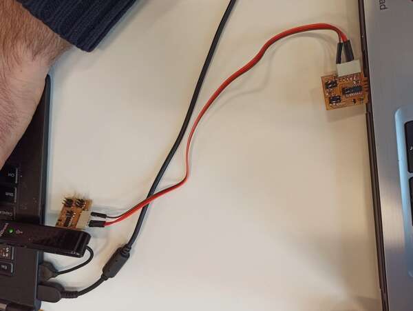
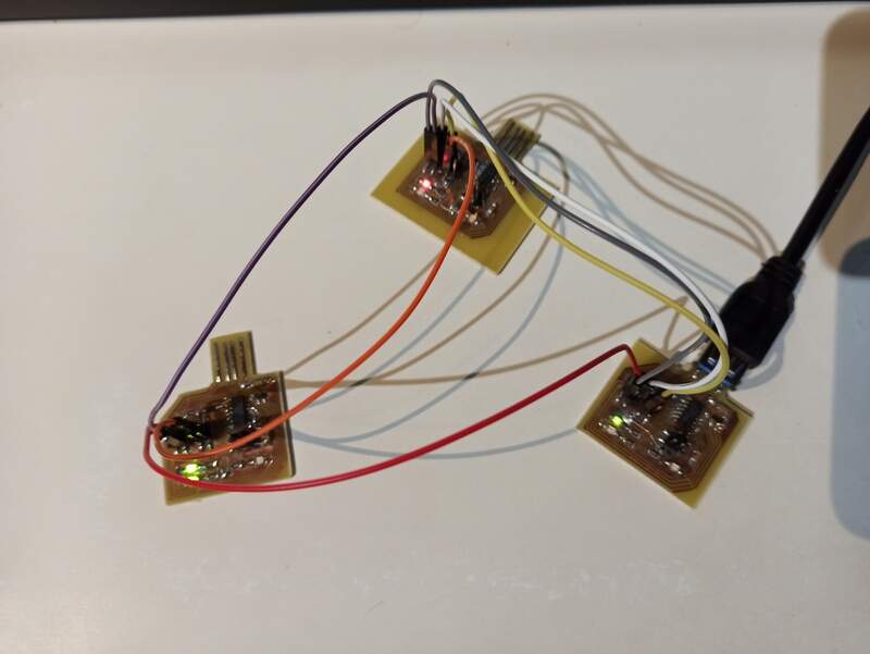
I updated the design with a third node (a second slave) with address ‘b’.

I forgot to add at least two 3.3V pins on my design so I had to connect my first slave to the 3.3V pin, and the second one to the 5V pin, both from the master (in a “star” configuration). In a perfect design, the 3.3V supply from one node would propagate to the next one.

Also, I initially had some issues making it work, because when I soldered my boards, I added all the 4.7kOhms pull-up resistors on all the boards. That made the communication line very pulled up and the communication was altered. I then realized it, unsoldered every 4.7k on the slave boards (as it should be, just didn’t think of it when soldering) and it finally worked flawlessly.

logo text
The 2 slaves and the master together

Making the LEDs subsequently blink


Commanding the indivual LEDs through the network

New code:

  1
  2
  3
  4
  5
  6
  7
  8
  9
 10
 11
 12
 13
 14
 15
 16
 17
 18
 19
 20
 21
 22
 23
 24
 25
 26
 27
 28
 29
 30
 31
 32
 33
 34
 35
 36
 37
 38
 39
 40
 41
 42
 43
 44
 45
 46
 47
 48
 49
 50
 51
 52
 53
 54
 55
 56
 57
 58
 59
 60
 61
 62
 63
 64
 65
 66
 67
 68
 69
 70
 71
 72
 73
 74
 75
 76
 77
 78
 79
 80
 81
 82
 83
 84
 85
 86
 87
 88
 89
 90
 91
 92
 93
 94
 95
 96
 97
 98
 99
100
101
102
103
104
105
106
107
108
109
110
111
112
113
114
115
116
117
118
119
120
121
122
123
124
125
126
127
128
129
130
131
132
133
134
135
136
137
138
139
140
141
142
143
144
145
146
147
148
149
150
151
152
153
154
155
156
157
158
159
160
161
162
163
164
165
166
167
#define MASTER //uncomment if programming master, comment for slave

#define startFrame 0x02 // STX :start of frame
#define endFrame 0x03 // ETX : end of frame
#define DLY 500
#define slave1Address 'b'
#define slave2Address 'c'
#define masterAddress 'a'

#if defined (MASTER)
  #define myAddress masterAddress
#else
  //#define myAddress slave1Address
  #define myAddress slave2Address
#endif

// init LED pins
int const led1 = 9;
int const led2= 14;
int const led3 = 15;

void setup() {
  SerialUSB.begin(19200, SERIAL_8N1); //USB serial prints
  pinMode(5, INPUT); // RX
  pinMode(4, OUTPUT); // TX
  Serial2.begin(19200,SERIAL_8N1); // UART
  pinMode(led1, OUTPUT);
  pinMode(led2, OUTPUT);
  pinMode(led3, OUTPUT);
  Serial1.end(); //Try to stop serial 1 (RX1, TX1) from communicating
  while(Serial2.available()){ //flush UART buffer
    Serial2.read();
  }
  SerialUSB.println("done setup");
}

#if defined(MASTER)

void loop() { //MASTER loop: write input data or pre-selected data to UART to slave1
  #if 1
  if(SerialUSB.available()){
    String input = "";
    byte slaveAddress = (byte)SerialUSB.read();
    SerialUSB.print("slaveAddress :");
    SerialUSB.println(slaveAddress);
    while(SerialUSB.available()){
      input+=(char)SerialUSB.read();
    }
    SerialUSB.println(input);
    delay(DLY);
    sendMessage(slaveAddress, input);
  }
  #else
  SerialUSB.println("start");
  sendMessage(slave1Address, "11");
  delay(DLY);
  sendMessage(slave1Address, "21");
  delay(DLY);
  sendMessage(slave1Address, "31");
  delay(DLY);
  sendMessage(slave1Address, "10");
  delay(DLY);
  sendMessage(slave1Address, "20");
  delay(DLY);
  sendMessage(slave1Address, "30");
  delay(DLY);

  SerialUSB.println("start2");
  sendMessage(slave2Address, "11");
  delay(DLY);
  sendMessage(slave2Address, "21");
  delay(DLY);
  sendMessage(slave2Address, "31");
  delay(DLY);
  sendMessage(slave2Address, "10");
  delay(DLY);
  sendMessage(slave2Address, "20");
  delay(DLY);
  sendMessage(slave2Address, "30");
  delay(DLY);
  #endif
}

#else
void loop() { //Slave loop: awaits data
  readMessage();
}

#endif

void sendMessage(byte address, String msg){ //adds start and end of frames
  SerialUSB.print("sent message : ");
  SerialUSB.print(address);
  SerialUSB.print(" ");
  SerialUSB.println(msg);//+ (char)address + msg);
  SerialUSB.flush();
  while(Serial2.available()){ //flush receive buffer
        Serial2.read();  
      }
  Serial2.write(startFrame); //Add SOF
  Serial2.write(address); // write slave adress
  Serial2.print(msg); //write command and params
  Serial2.write(endFrame); // add EOF
  Serial2.flush(); //awaits for all outgoing data to be sent
  readMessage(); //reads back the info to make sure it is correct
}

void readMessage(){
  String receivedMsg = "";
  bool done = false;
  char c;
  byte d;
  int counter = 0;
  if(Serial2.available()){
    SerialUSB.println("reading message...");
    if( (d = (byte)Serial2.read()) == startFrame){ //checks SOF
      SerialUSB.println("start frame detected");
      counter = 0;
      while((!done) && (counter < 100)){ //gather all data
        if(Serial2.available()){
          c = (char)Serial2.read();
          if(c == endFrame){ // until EOF
            done = true;
          }
          else{
            receivedMsg += c;    
          }
        }
        counter++;
      }
      SerialUSB.println("received message : " + receivedMsg);
      if(receivedMsg[0] == myAddress){ //check address
        char cmd = receivedMsg[1];
        char param = receivedMsg[2];
        processMessage(cmd,param); //if for "me", process it
      }
    }
    else{
    SerialUSB.println("invalid message");
    SerialUSB.println(d); //wrong SOF
      while(Serial2.available()){
        SerialUSB.print((char)Serial2.read());  
      }
    }      
  }
}

void processMessage(char cmd, char param){//decomposes message in command and params
  //SerialUSB.println("processing message : " + String(cmd) + " " + String(param));
  int led;
  switch (cmd){ //selects led accoridng to cmd
    case '1': led=led1; break;
    case '2': led=led2; break;
    case '3': led=led3; break;
    default: led=0; break;
  }
  if(led!=0){ //switch on or off the led
    int state;
    if(param == '1'){
      state = HIGH;
    }
    else{
      state = LOW;
    }
    digitalWrite(led, state);
  }
}

My design files

My Design files


Last update: June 16, 2021 10:33:59