7. Computer-Controlled Machining
Objectives
- Group assignment: Do your lab's safety training.
- Test runout, alignment, speeds, feeds, materials, and toolpaths for your machine.
- Make (design+mill+assemble) something big (~meter-scale)
Introduction
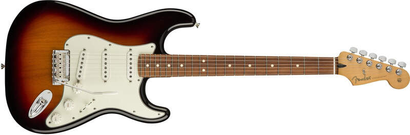
This week is about making something “big”. It started with a lack of interesting idea and I didn’t want to make “just” another table or chair… Got it ! Let’s make an electric guitar !
Introduction to the CNC
This is a recap of what is described in the group assignment page. Before I dive into the extremely complicated design of my guitar, I spent an afternoon with Christophe so that I could get an understanding of how the CNC works and what I can/cannot do with it.
The CNC itself
The CNC is a computer-controlled machine that generally means is motorized and can move in multiple directions, according to the files that are fed into the program. In this particular case, when I refer to the CNC, I will refer to the CNC machine that we have at our Fablab: a HIGH-Z S-1000 that is controlled with the Kinetic-NC software.
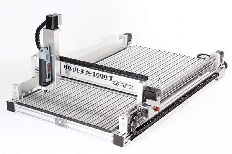
Using the correct milling bits, it is able to cut through wood, aluminum and some other materials in 2.5D (i.e. 2D with different heights and depths).
Equipment
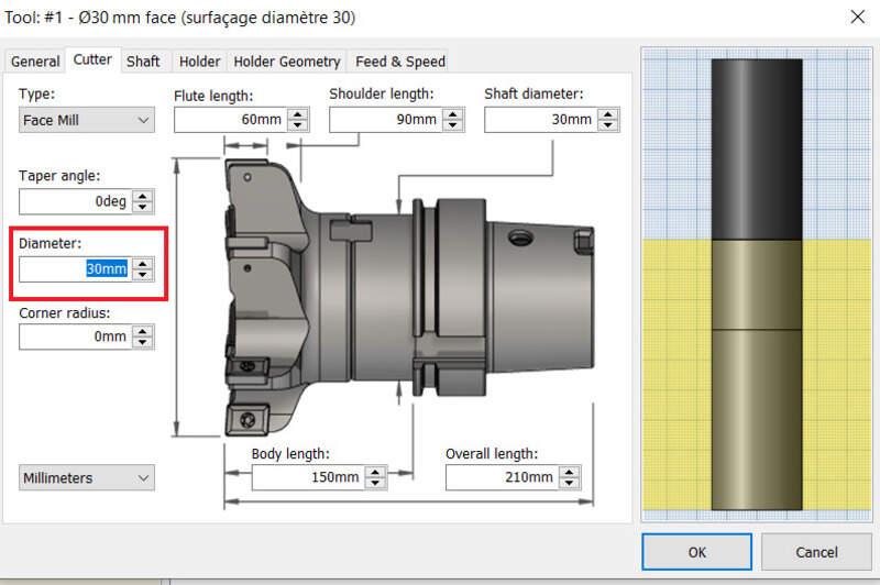
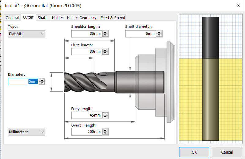
We lack a bit of mills at the Fablab so we were limited to using only 6mm and 3mm flat mills (201043 from Hoffman Group). Mills are usually defined by a few parameters: - The material they are made of - Their diameter - The number of flutes (i.e. the number of sharp edges at the bottom of the mill) - The surfacing speed (in m/min) - The feed per tooth (mm) - The cutting, shoulder and total length
Most of these parameters depend on the material we want to cut and not all mills are adapted to every material. It is therefore extremely important to use the reference catalog.
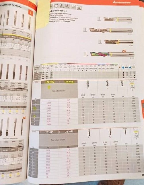
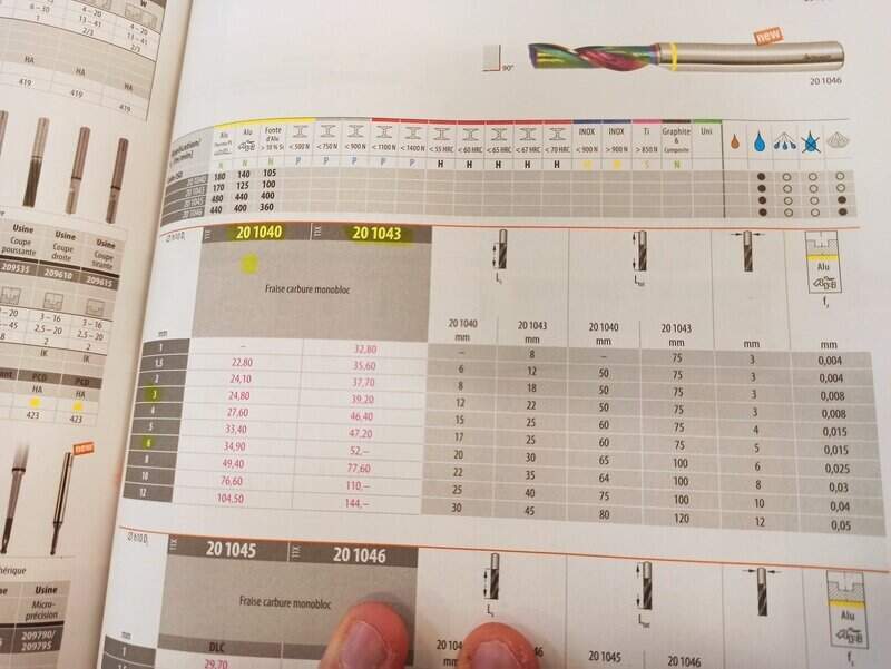
Note that wood is almost never indicated so we take the aluminum parameters. Some mills require coolant but we do not have any at the lab and when working on wood, it must not be used otherwise the wood will be soaked.
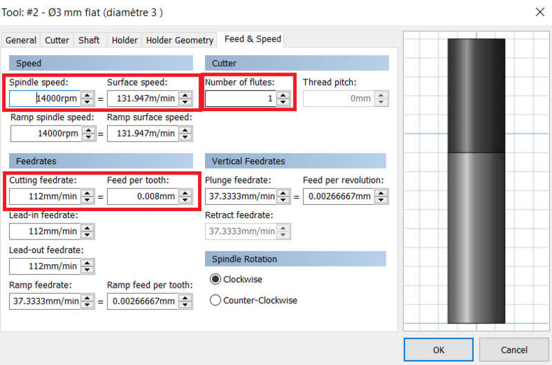
We can see that in the case of our 201043 mill with 3mm diameter, we can use a surfacing speed of 170m/min and 0,008mm of feed per tooth. The cutting length is 22mm and the total length 75mm.
The surfacing speed and the diameter will have an impact of the rotation speed (spindle speed), luckily, the CAM software computes this for us. However, our CNC has only present spindle speed settings (9000, 14000, 20000rpm mainly) so we must choose the closest one and adapt the surfacing speed to it.
The Kinetic-NC software is pretty easy to use and has two mains menus: jog and program. The first one allows to move the CNC around manually and zero the machine. The latter is used to load a CAM process and run. We can also slightly adjust the parameters once the program is running (0-150% spindle speed and feed per tooth).
Safety
A CNC machine can be a dangerous tool. The one at our lab cannot run whenever its doors are open and is automatically stopped whenever a door is opened. Moreover, one must always stay close to it when running in case something goes wrong. Cutting causes a lot of friction and heat and one must be extremely vigilant about it.
Also, it is always better to double-check your CAM process in the CAM software and in Kinetic-NC. An “air pass” is usually recommended at least for the first job on the part to make sure the stock is correctly placed and the zero is correctly set.
A CNC working can be quite loud so ear protections are recommend, especially if you spend your whole weekend in the lab  . Eye protection can be useful especially if the CNC is open, in which case a dust mask can also be proven useful.
Dust collection
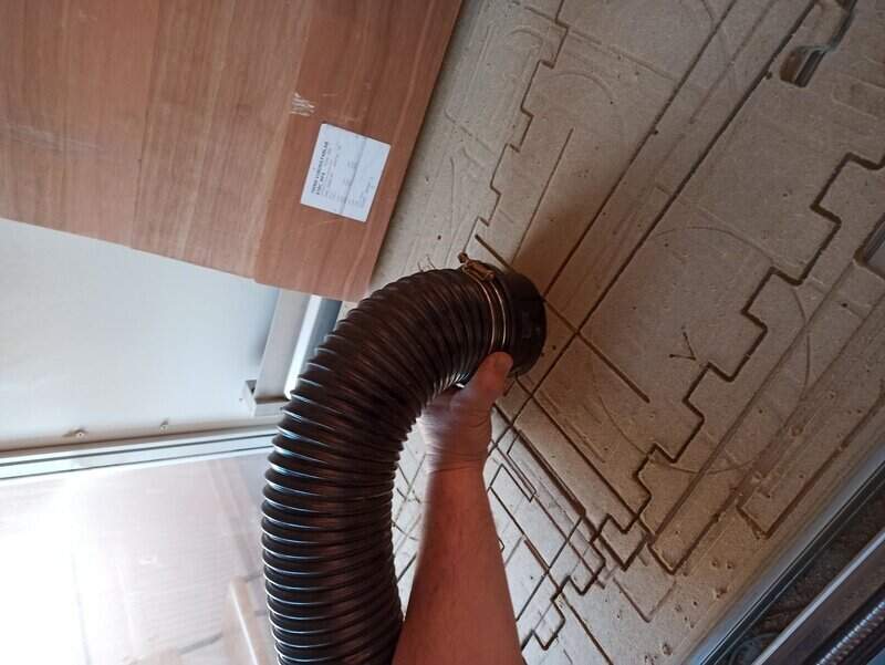
Because CNCing something will create a lot of waste material, it is important to remove them in-between two jobs. I used a cyclone vacuum to remove most of the waste material but it ended up a bit blocked at the end… I then used a classical vacuum cleaner.
Making a CAM design
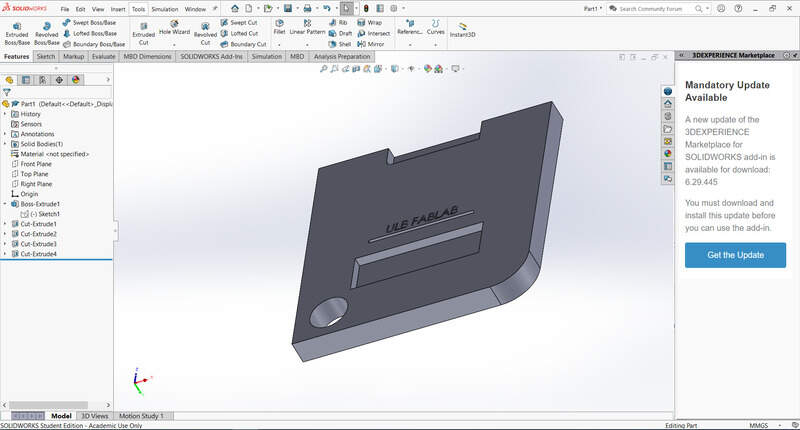
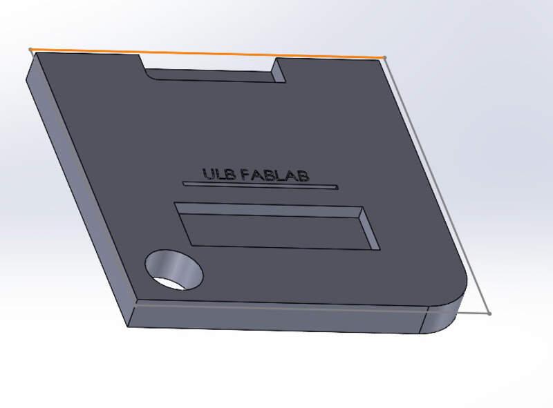
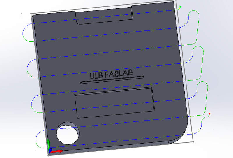
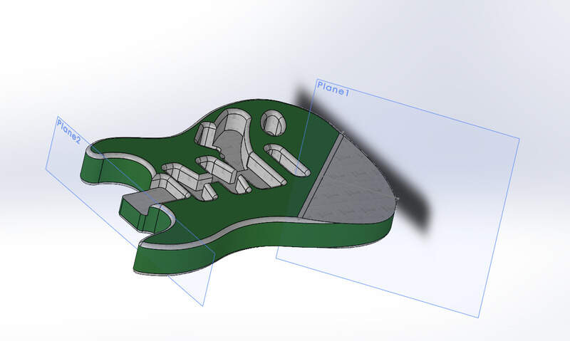
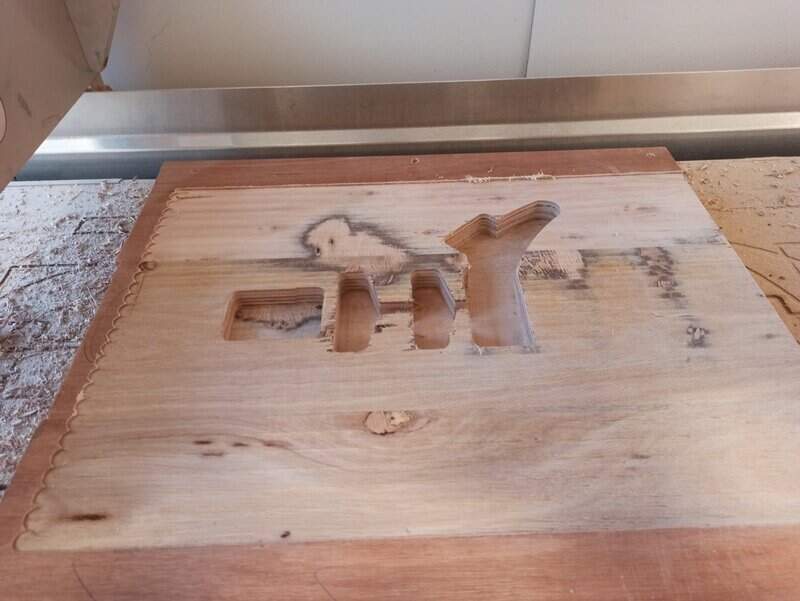
To test the CNC possibilities, I designed a small piece in SolidWorks that features sharp and round edges, engraving and enclosed and open holes (through all and blind).
That was the easy part. Now time to make the CAM job. Since I use SolidWorks, I had to install a CAM addon (newer SolidWorks version should have it installed but I didn’t for whatever reason). I went with the Autodesk HSMWorks software (free for edu students… How to access it after then ?).
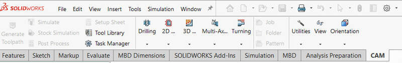
Once installed (and the computer rebooted), a CAM menu appeared on the top ribbon.
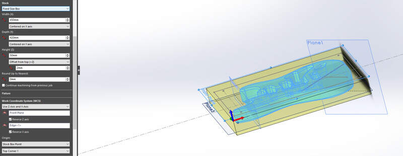
Setting up the job
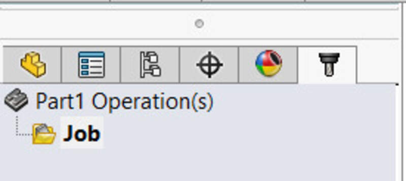
The first step is to create a new job.
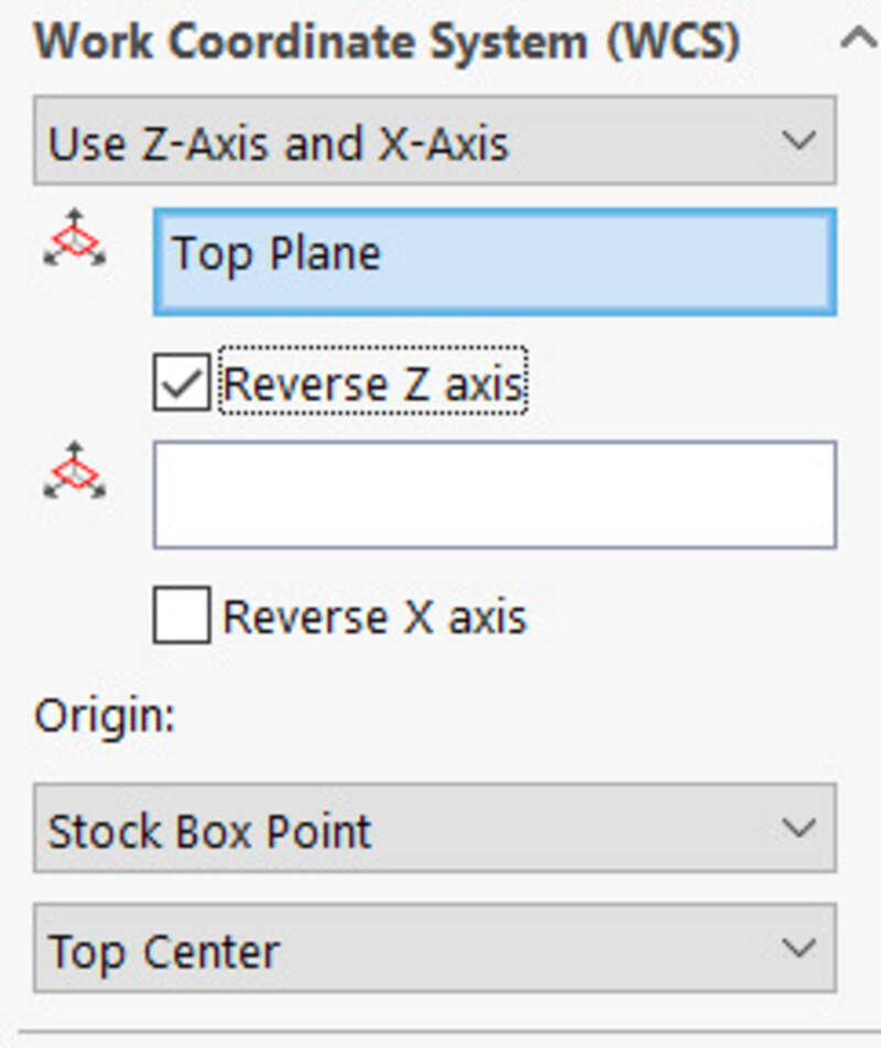
Inside the job settings, I need to set the coordinates system (selecting edges that will be my X and Y axis and a zero-position for the machine). On our CNC, the X axis is the longer one so I place the X axis along the longest edge.
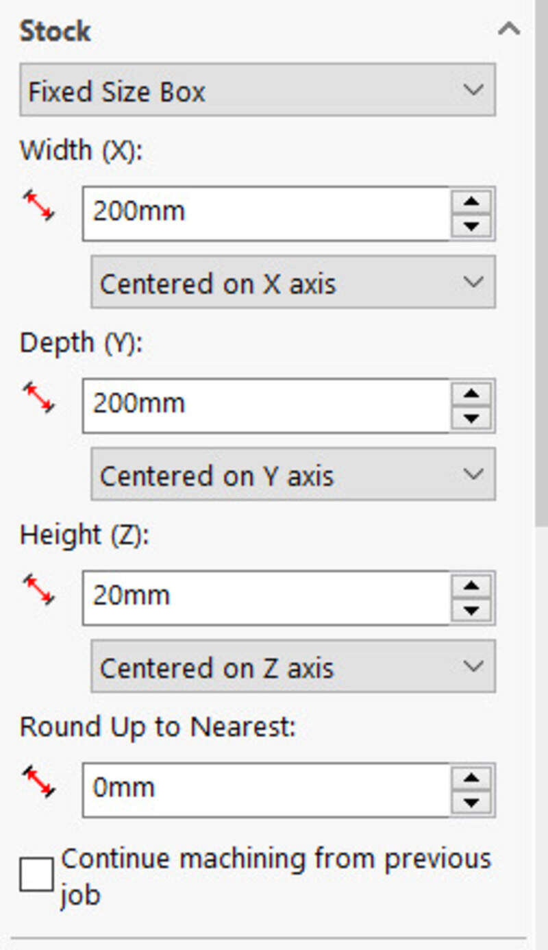
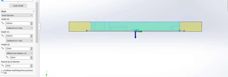
Then, I set the dimension of my stock, in this virtual test, I set my stock to be a fixed size box of 300x300x22mm.
I could then set my zero-position of the machine to be the either a selected point on my model or another point such as the top left corner of my stock.
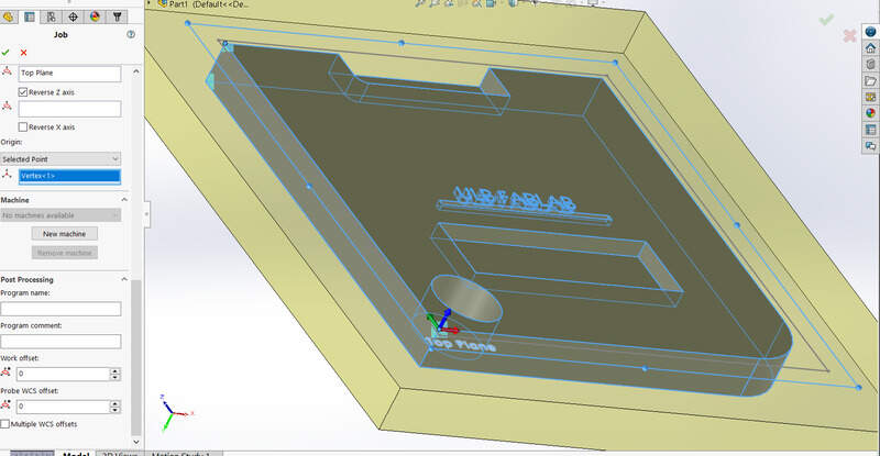
One need to be very careful about the orientation of the axis, in particular the Z one.
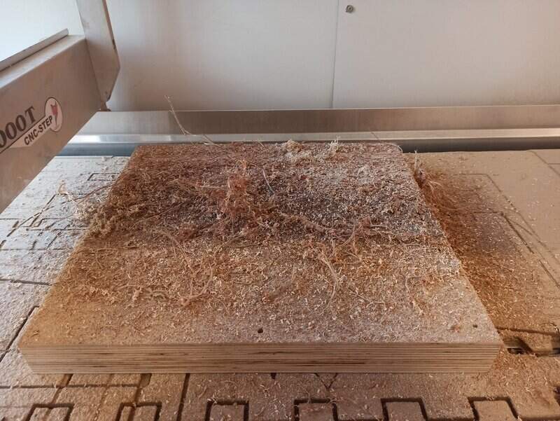
Surfacing the part
The first step is to surface the part. This will create an even surface for the part relative to the machine axis and will ensure that the finish surface is smooth and “new”. To avoid surfacing the whole surface of the CNC or the whole stock, I can create a new sketch that will be my surfacing boundaries (Later I found that I could actually surface the model contour, see below).
Tool library
I then had to choose the tool that I was going to use for this job. Usually, this step is done once for all projects and the mills are stored in a tool library but for this first time I had to do it now.
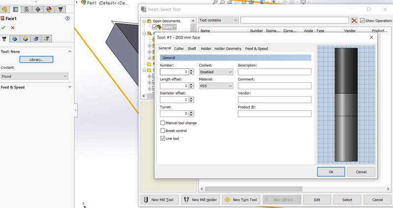
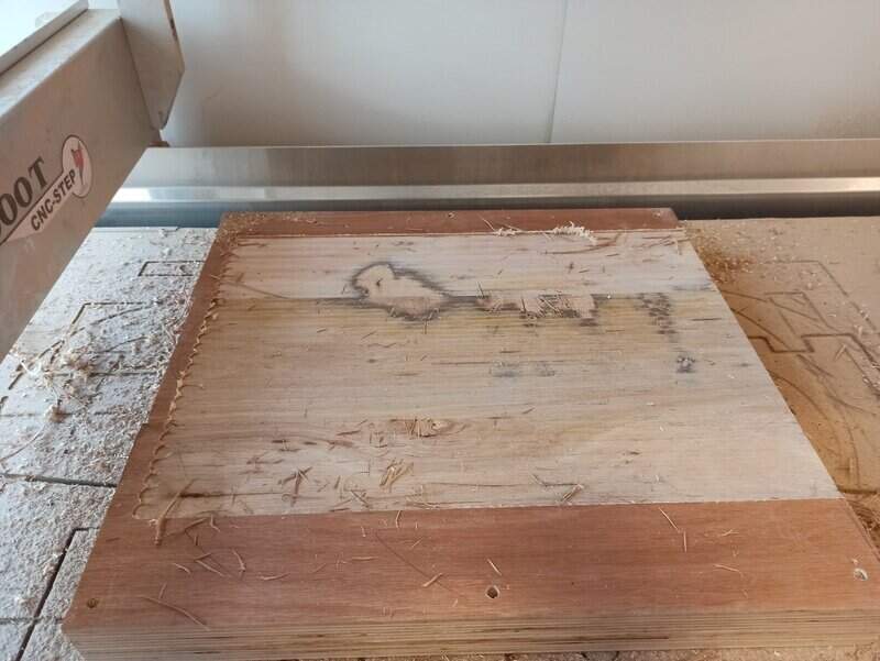
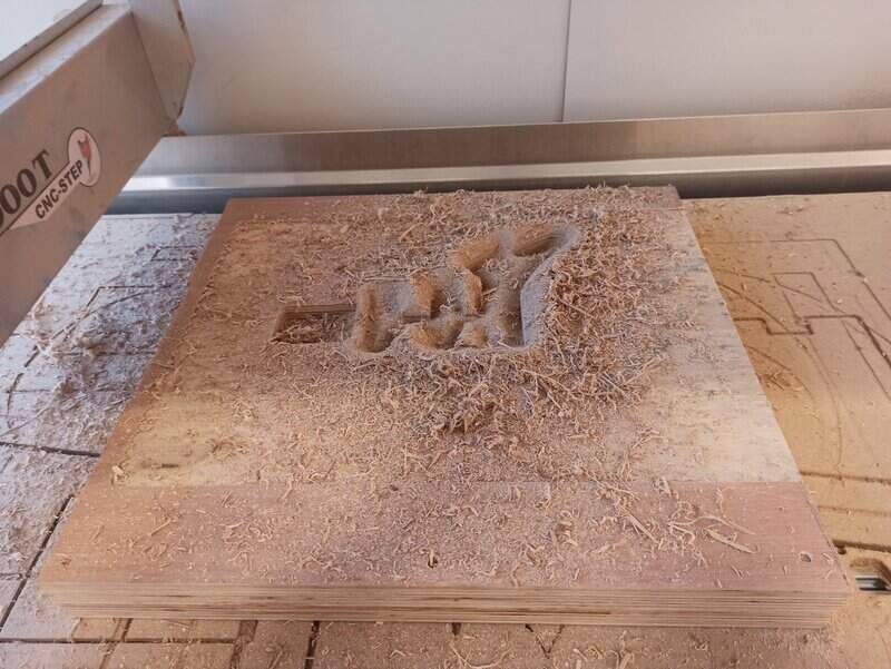
I could then set several settings for my surfacing: the contour to surface but also the height (top and bottom), the stepover between each pass and the maximum depth of a pass (usually set to maximum half the diameter of the mill, in this case I used 2.5mm for a 6mm mill). Here is the result of the surfacing job.
2D Pocket
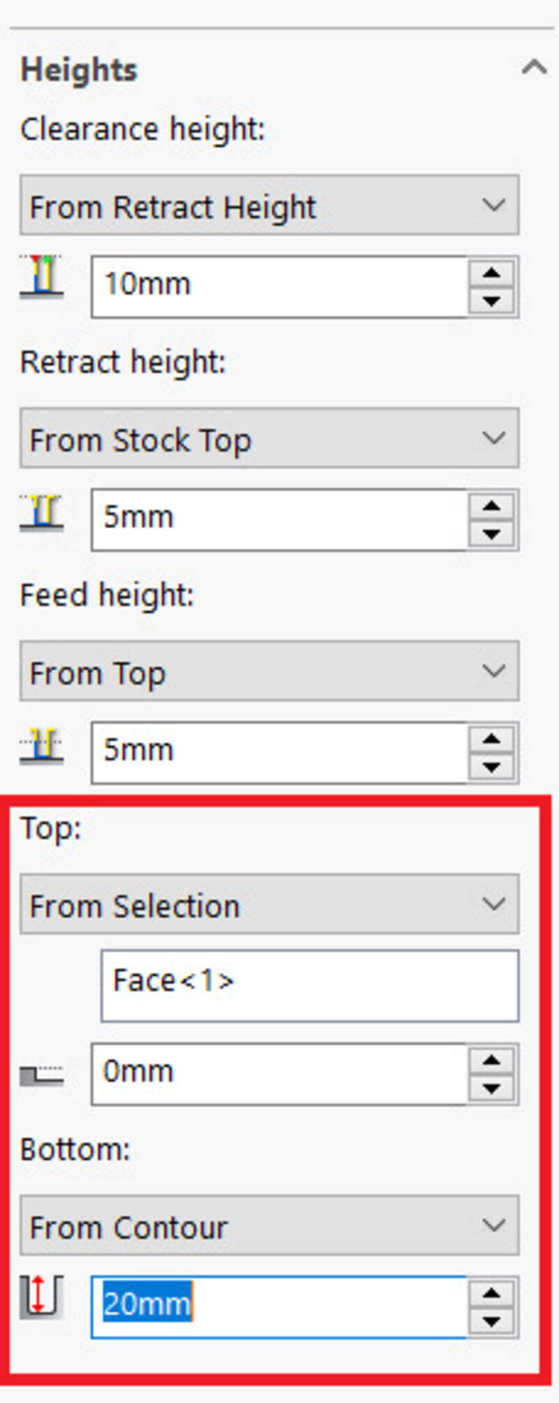
A 2D pocket is a job that allows to cut inside the part to make a hole (a pocket). One must select the contour and either the bottom height or the contour surface to set the depth. It is extremely important to set the “multiple depths” settings to on to preserve the mill.
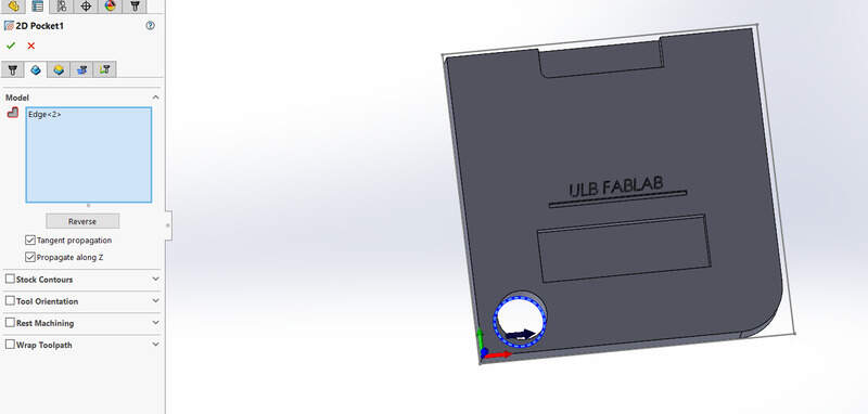
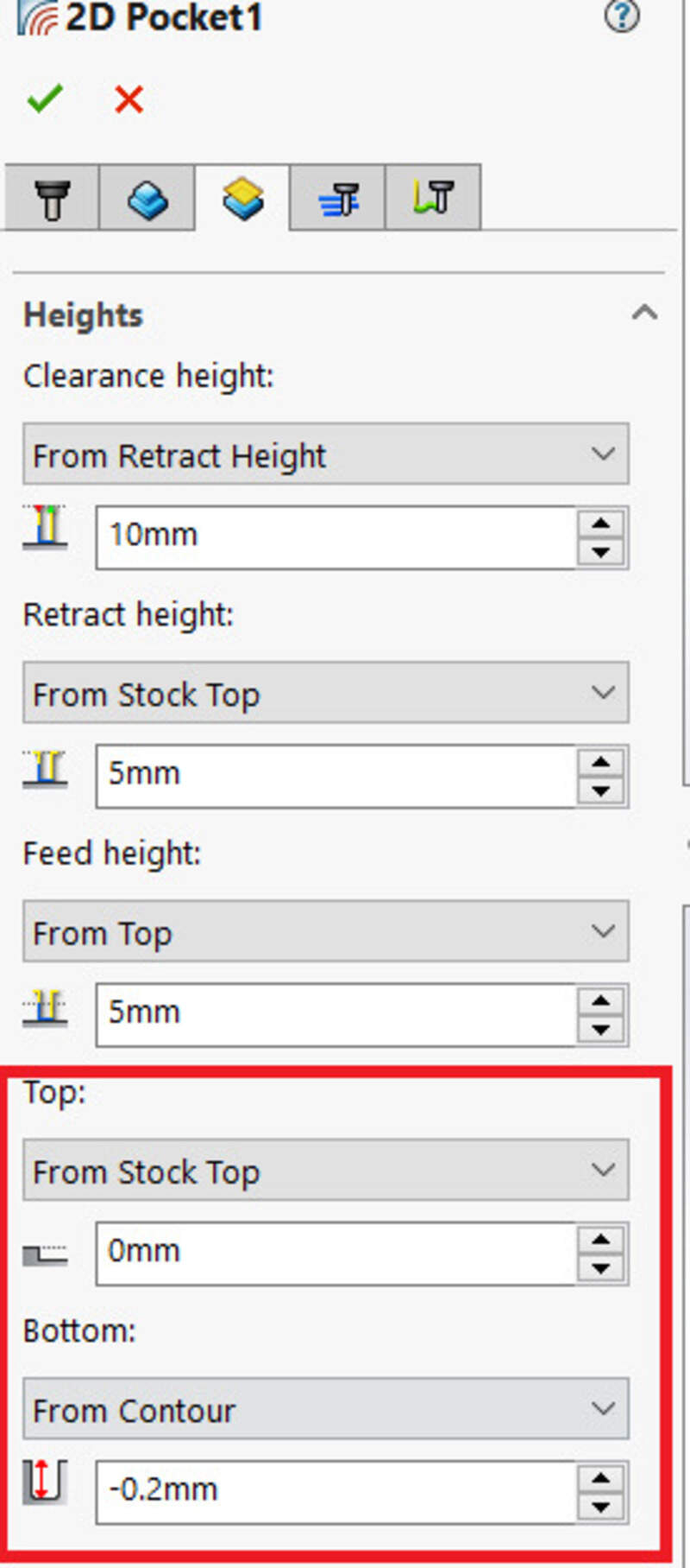
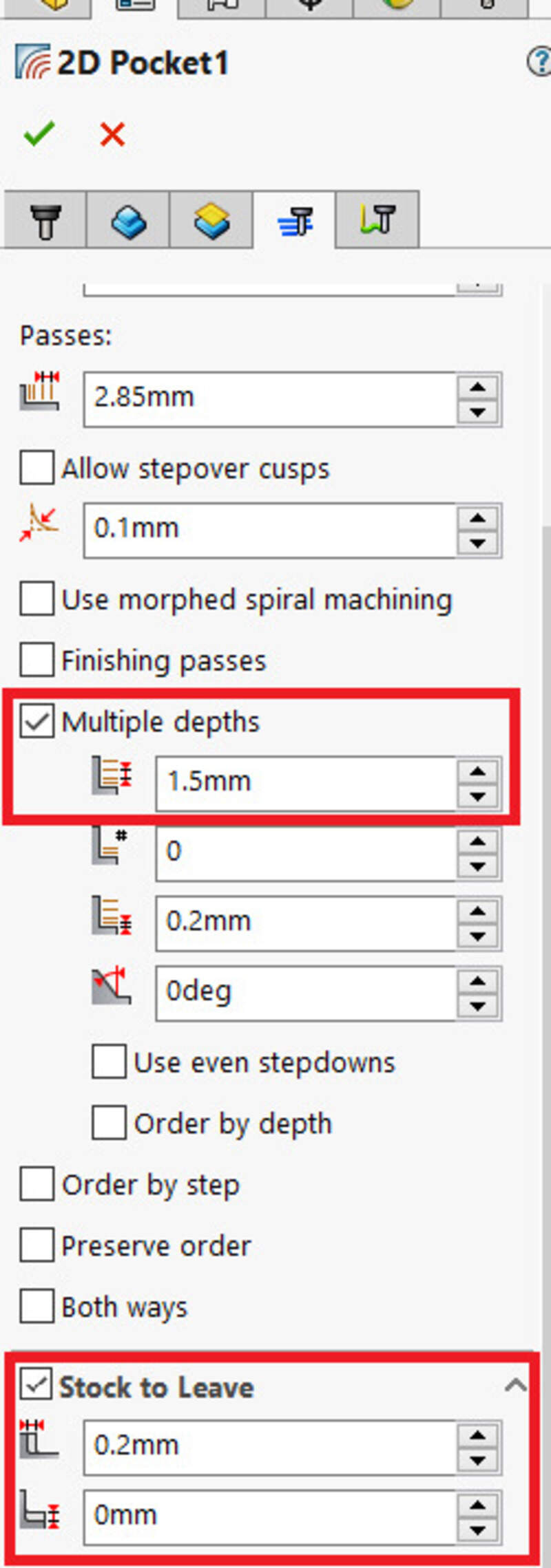
One can set a “stock to leave” if using a big mill to then finish the job with a softer touch and a smaller mill (using the 2D contour job). If only one pass (which I did for my guitar as I had not much time, then set it to off !).
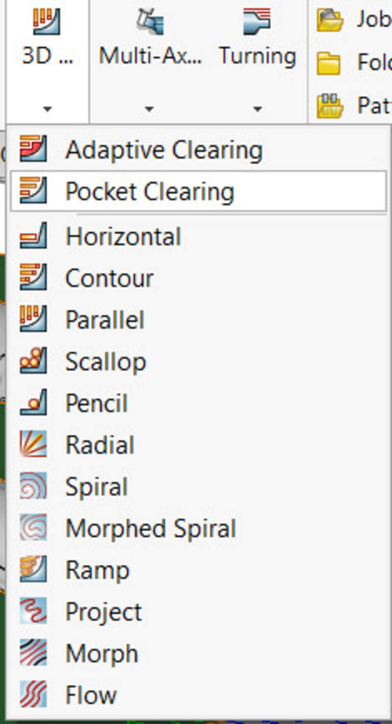
2D Adaptive and other
Adaptive clearing means that the program will try to compute the path to reduce the load on the mill. However, this usually result in a longer toolpath but the material undergoes less force and pressure so the finish is usually better. There is no multiple depth settings there.
A lot of the options are also available. In particular, the 2D engraving too but also the 3D jobs that allow to make slopes with the parallel, 3D pocket, 3D adaptive, scallop jobs, … I used some of them to make my guitar.
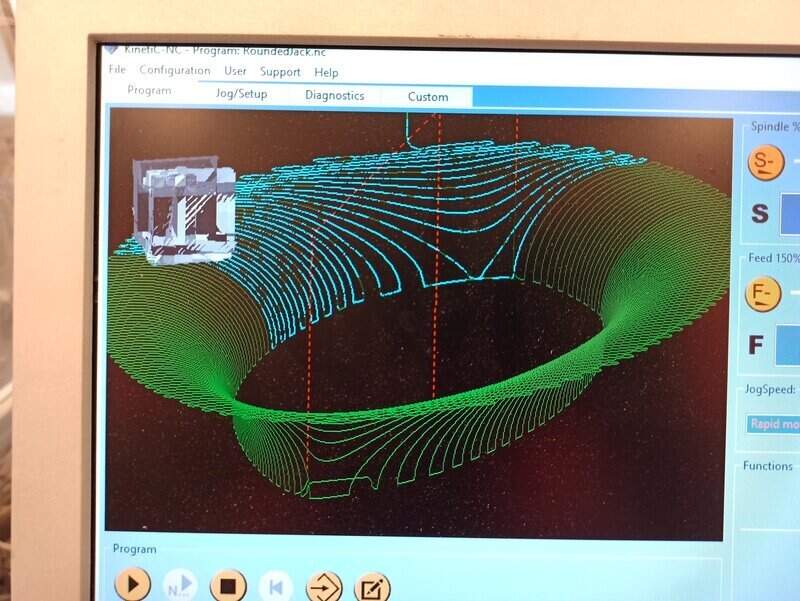
Simulating
The final step before exporting the CAM is to simulate it. This allows to see the time it will take and help detect any issues. I highly recommend to do it.
Testing the machine
Jason and I tested the runout and the alignment of the machine by visually inspecting the axis of the tool when rotating. We also measured the horizontal distance between the end of the mill and the mill axis with a caliper at different points in the rotation, similarly to what is done in this video.
Christophe also indicated to us the best feed rates and spindle speed for cutting through the wood (see above).
Making my guitar !
Getting inspirations and references
So I started off looking for inspirations and plans… Since I’ll have to design it in a CAD software, better to have some good references before starting to work.
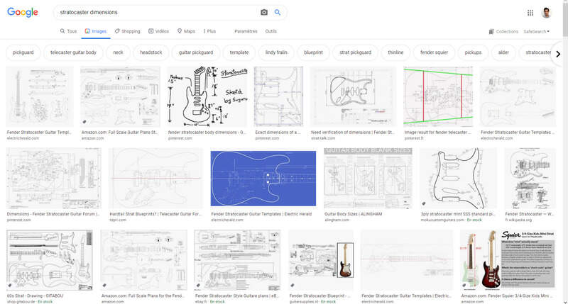
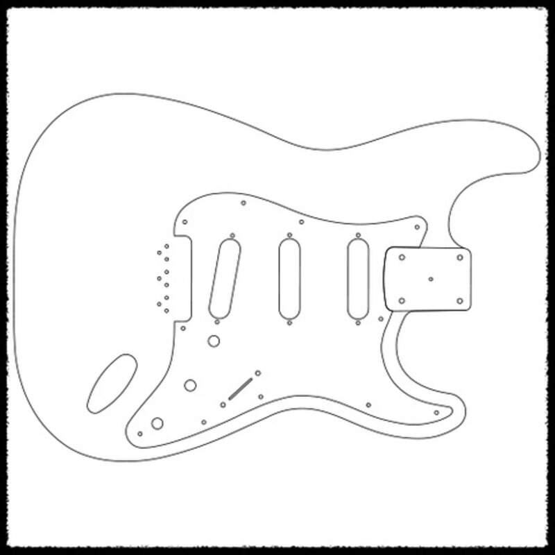
I found some plans online but most of them were extremely pricey (we talk about 30-100$ for the plans, ouch)… Until I foud this gem
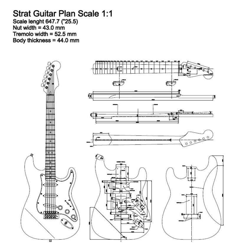
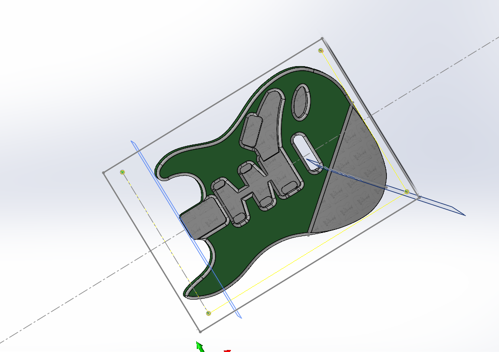
The CAD design
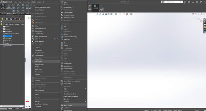
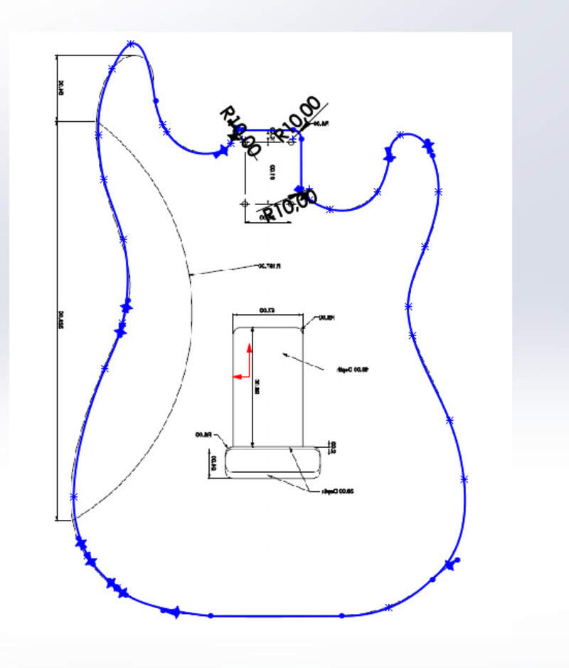
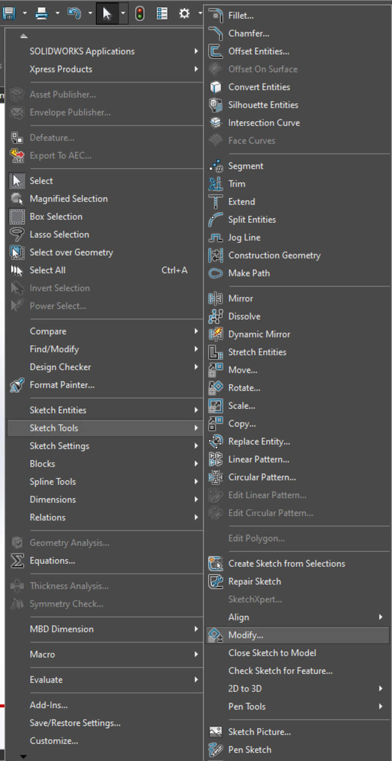
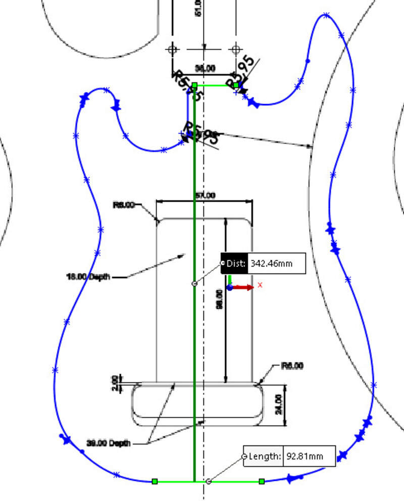
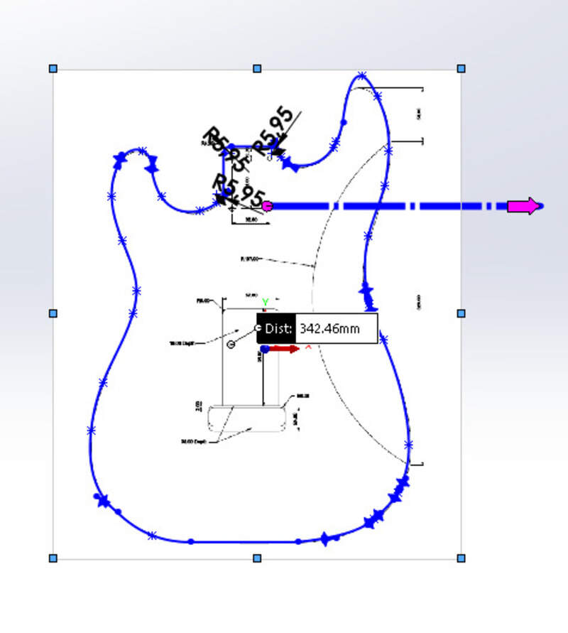
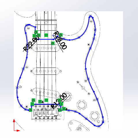
I used Solidworks to design my guitar. I used this nice little tool available in SW to import a .png inside my sketch so that I can “copy” the shape of the guitar and I use the dimensions reference on the plan. The steps are: Tools menu - sketch tools - sketch picture
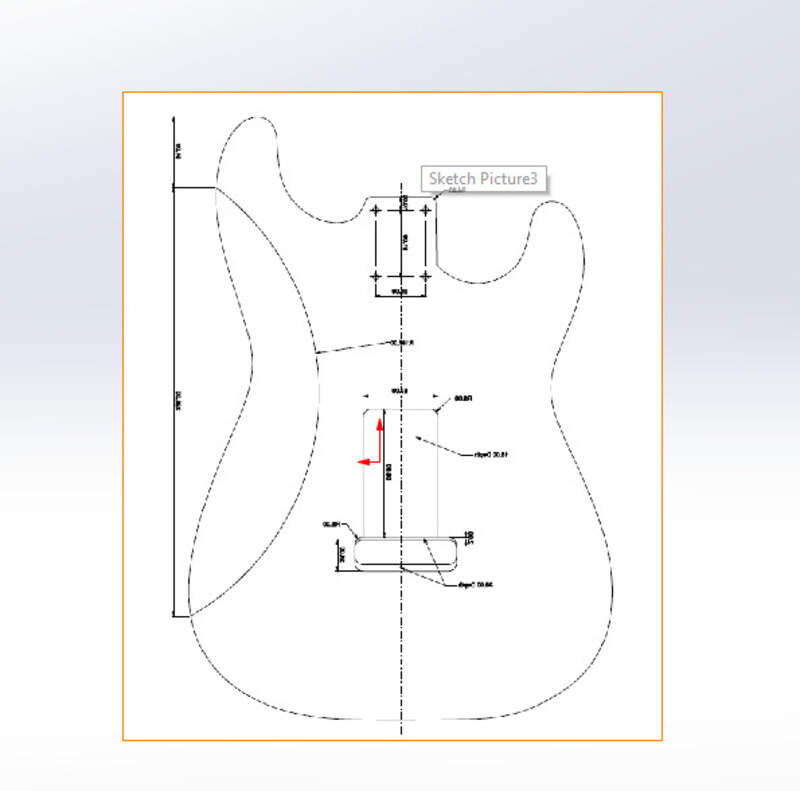
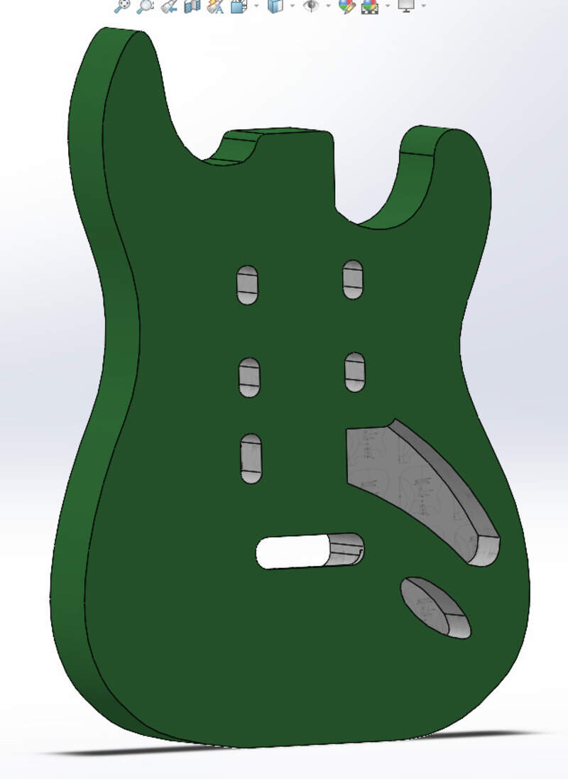
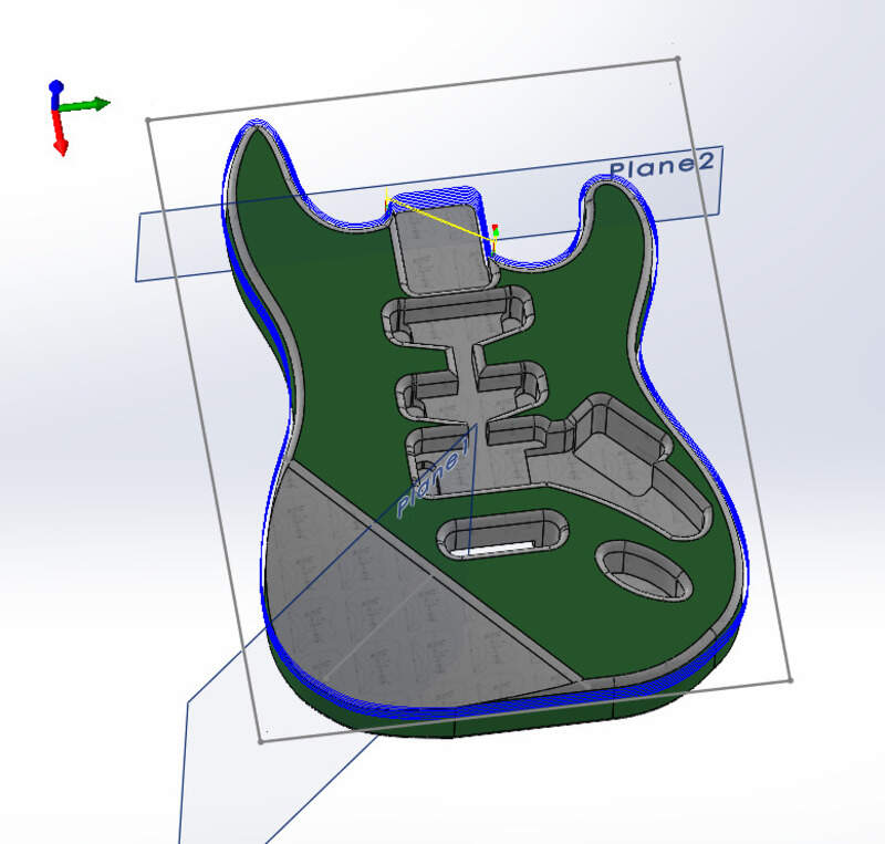
I started with the face “A” (or the top face). I used straight lines but also splines (and adjusting them multiple times), ellipses and sketch fillet. I also took some liberties on the upper part on the shape to make it more “my own”.
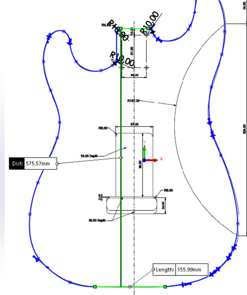
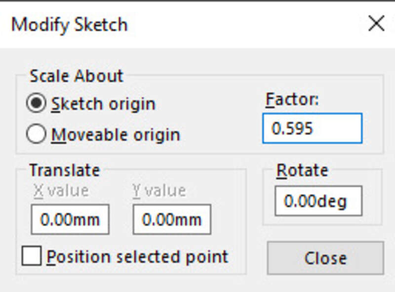
until I realized it was not the correct size . Obviously the png had been resized. So I used Inkscape with the 1:1 template, some SolidWorks measurements and a bit of math to compute the length between the neck and the bottom (344mm). I then scaled my SolidWorks sketch to get this distance.
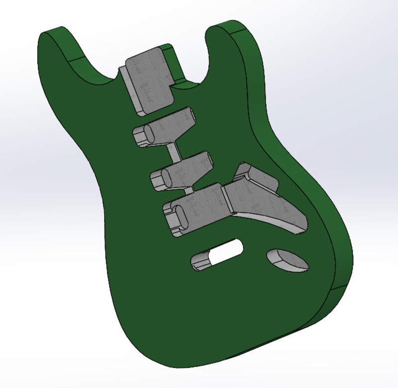
Let’s extrude and boss everything we need. In a tens of minutes of work, the bottom is done !
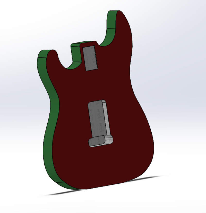
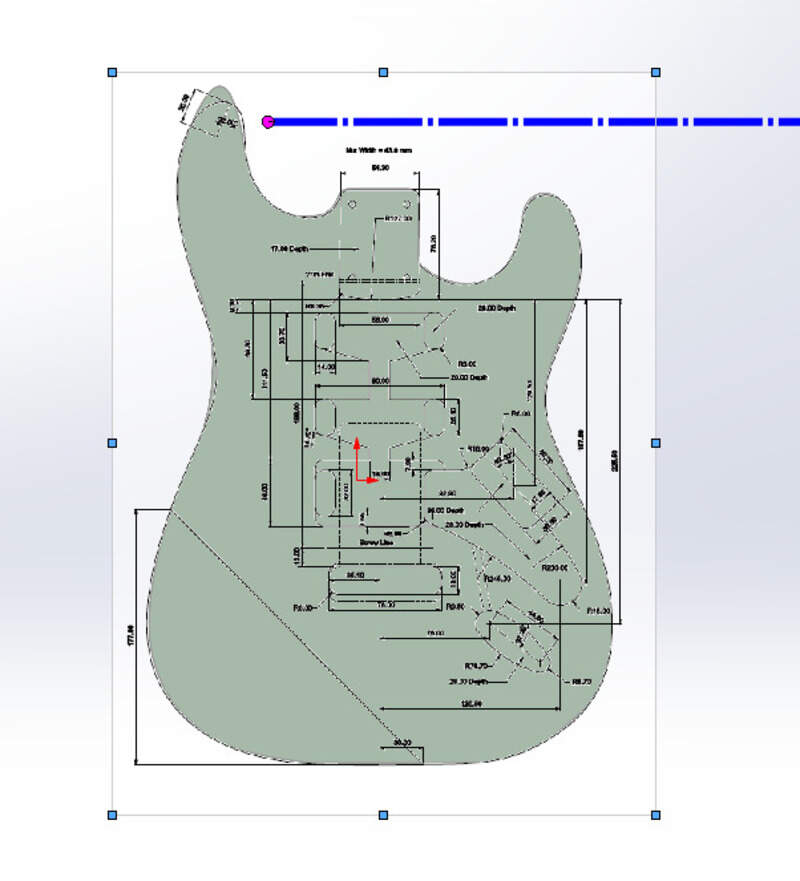
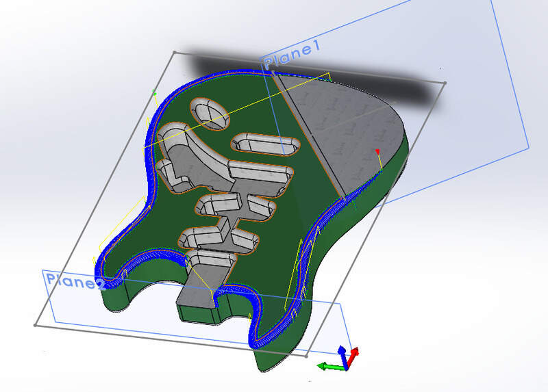
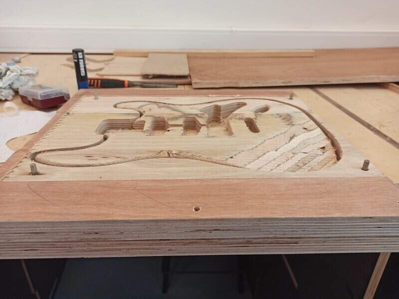
For the top part, all of the holes are different depth so here are the intermediate and final results !
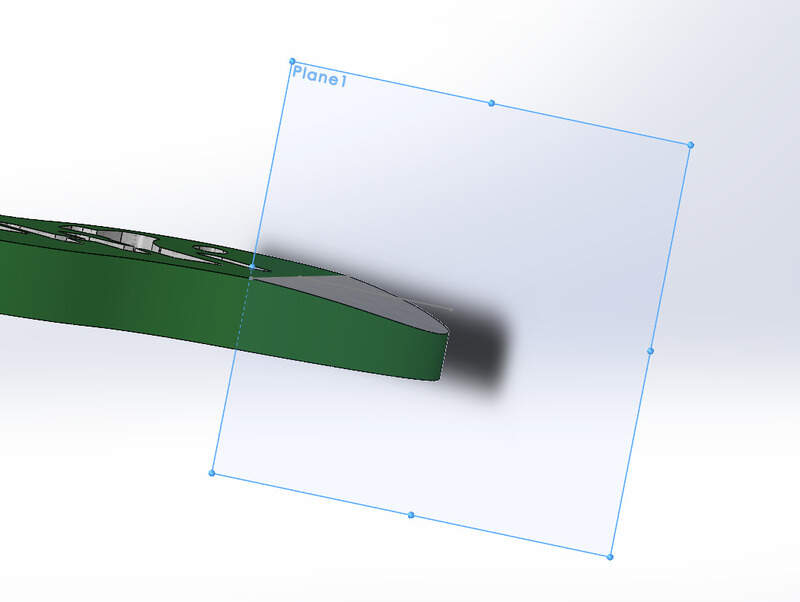
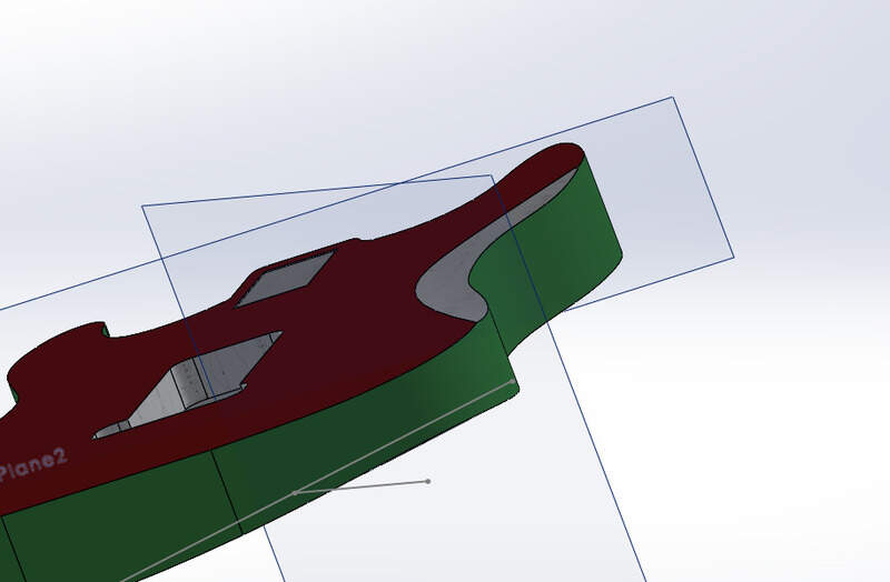
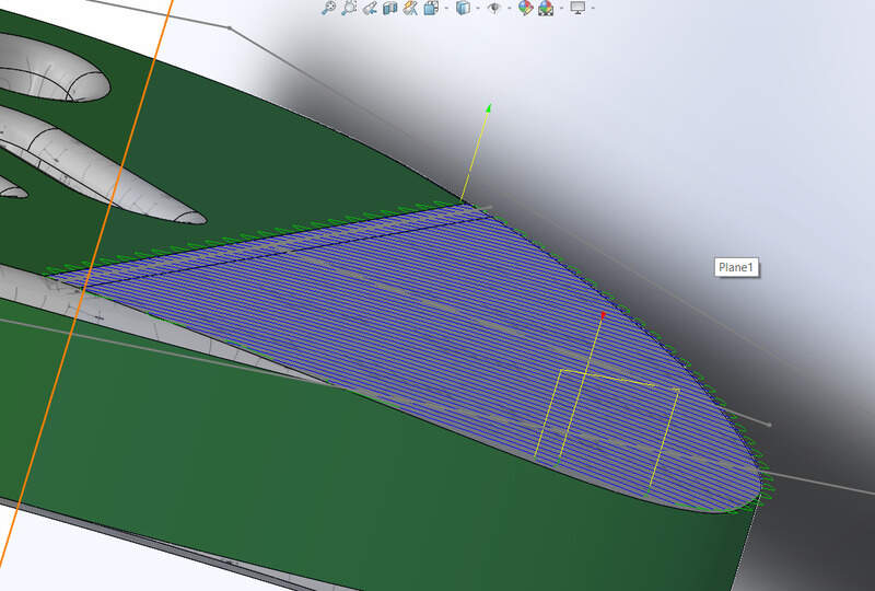
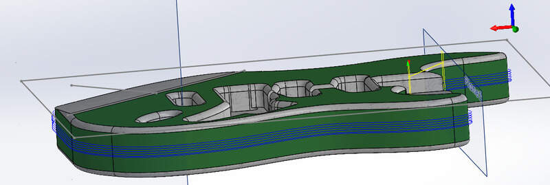
I then created a new reference plane to be able to make the slope.
Making the guitar !
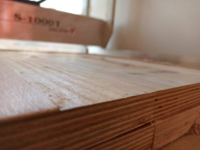
Making the stock
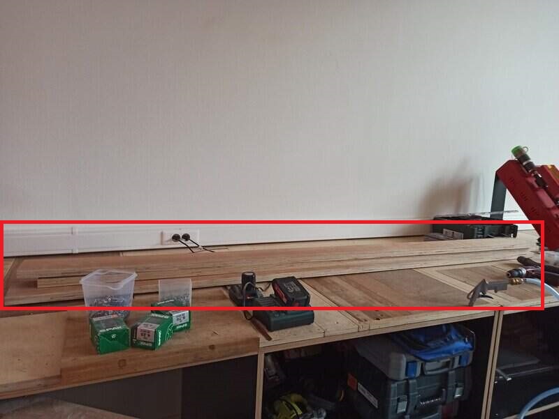
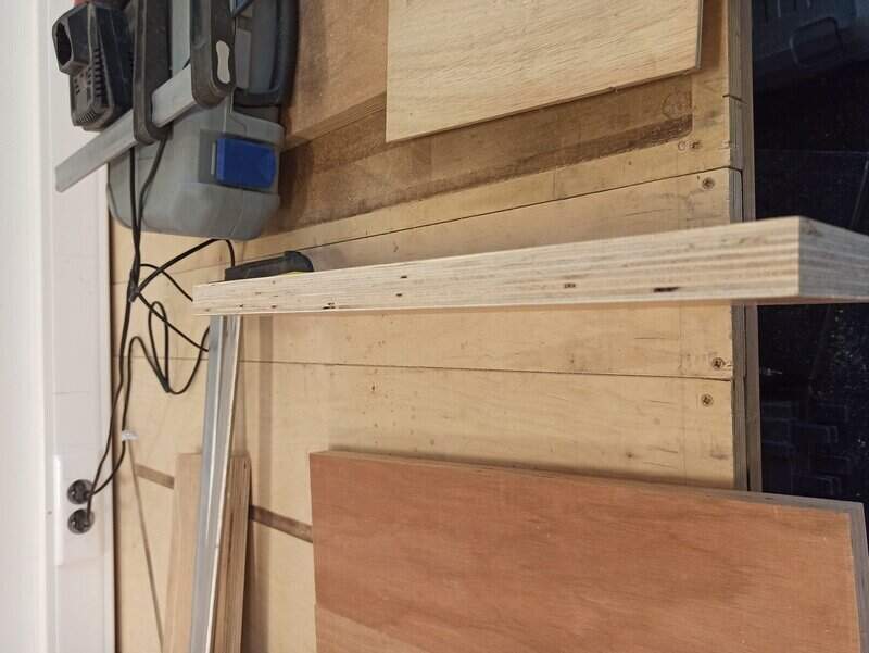
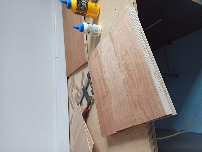
My guitar requires 420mmx300mmx44mm. So I needed to make a stock bigger than that with the wood available at the lab. I chose to go with long planks that are 25mm thick and 110mm large. I had to cut them at 450mm and assemble them by 3 then times 2 to make a whole body that was big enough.
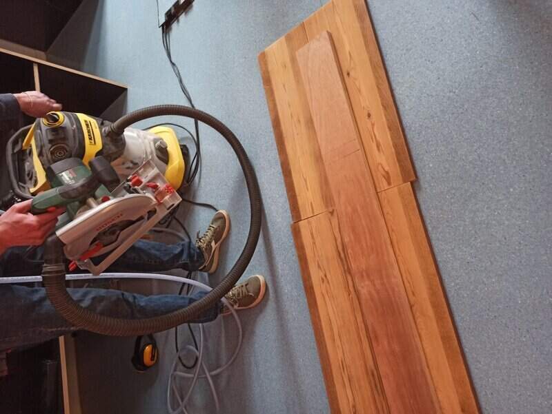

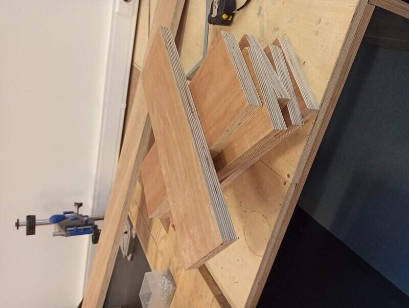
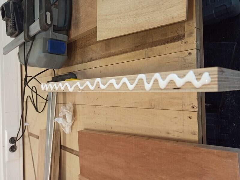
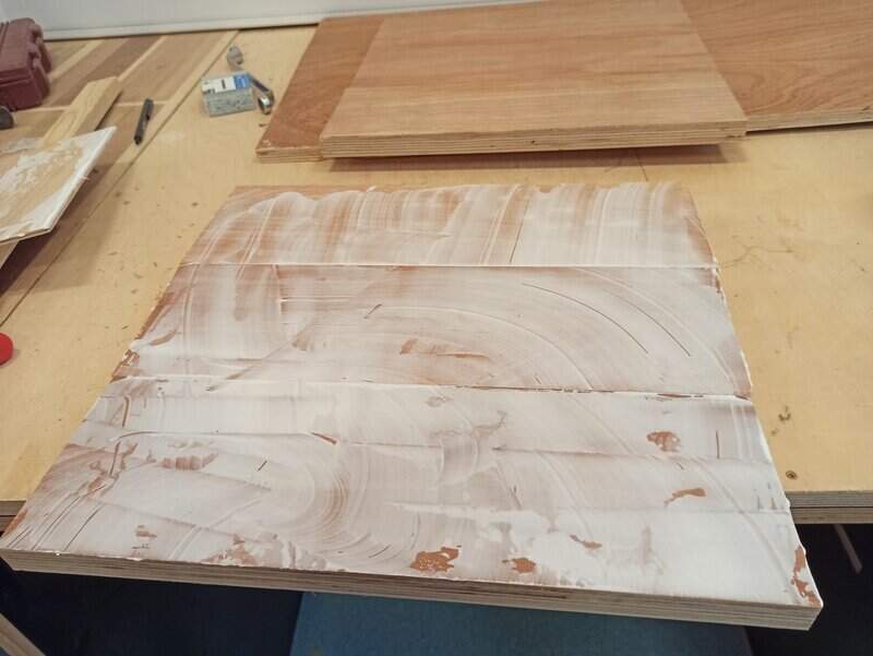
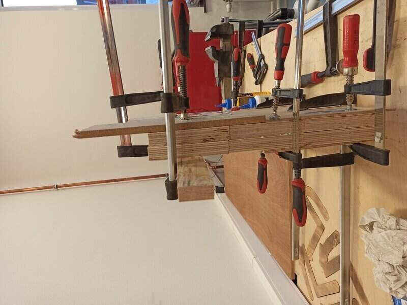
Then I had to glue them together. I used wood glue and clamps to hold them in place for 2 hours.
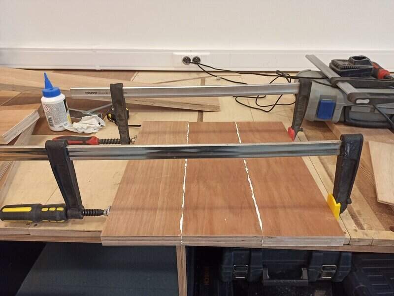
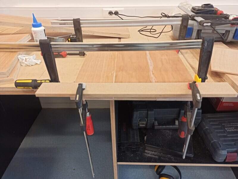
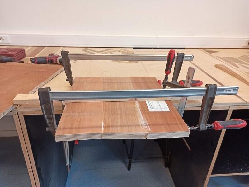
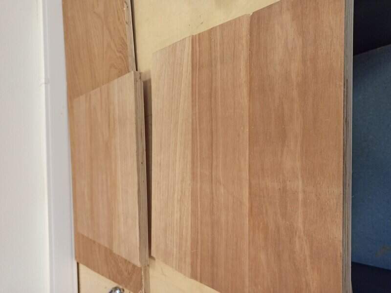
I then needed to assemble my new board of 3 planks with another one to make a stock 50mm high.
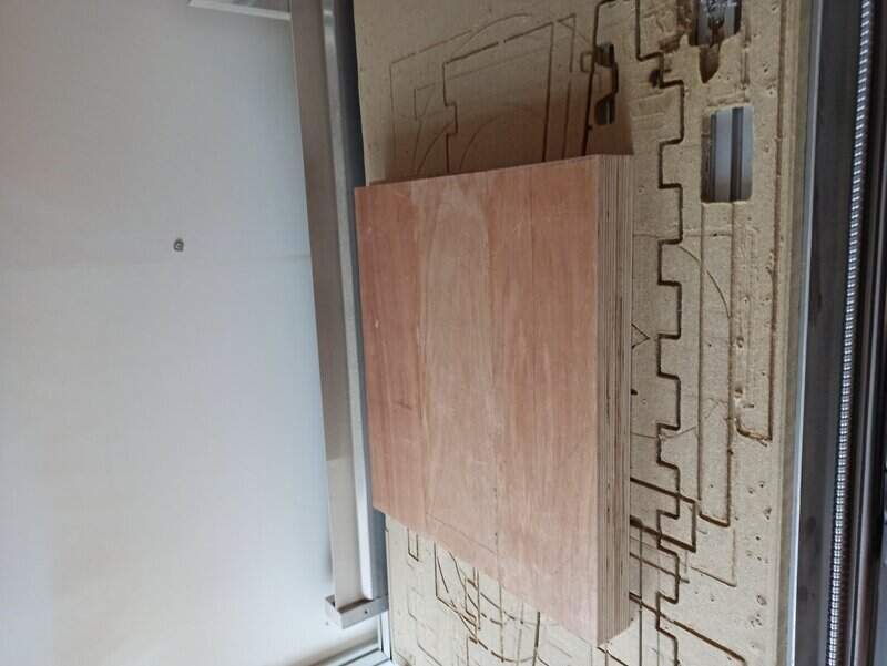
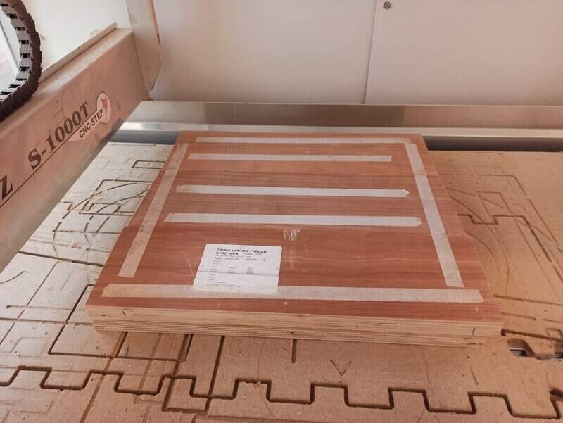
Placing the stock
I made sure to vacuum clean the spoilerboard and added double-sided tape and screws to hold my stock well in place.
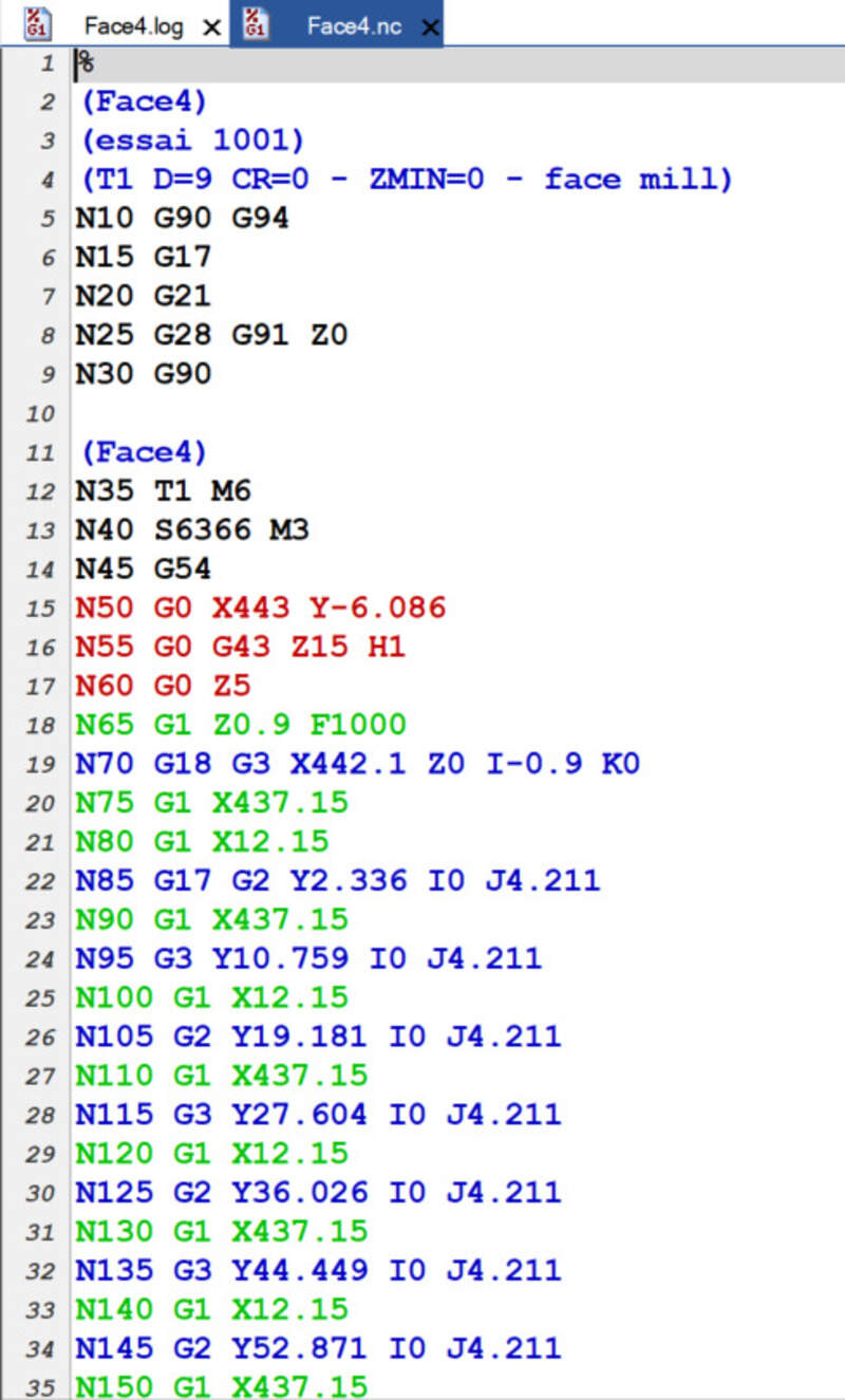
Post-processing the CAM
So the first step before actually being able to mill is to export the GCode for the machine. I had to install the post-processor kinetic-NC. It is available here.
Then I tried to postprocess my design and ran into this:
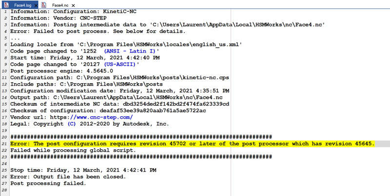
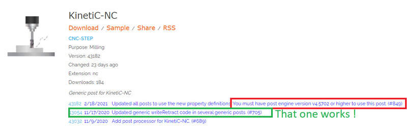
Actually it is because the version is too recent compared to the engine used in SolidWorks (or HSMWorks maybe ?). Anyway, I found an older version (43054) that works !
Tools
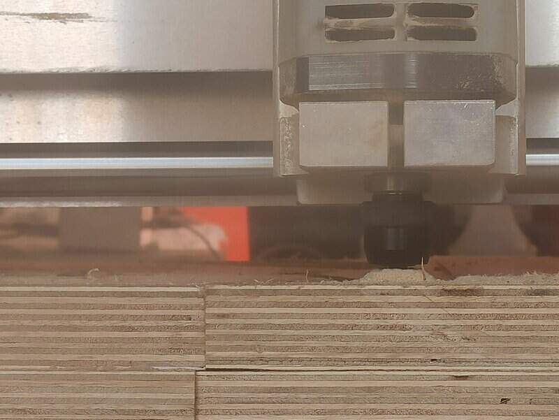
Now I’m entering the real tool that I’ll use: the might 6mm flat end.
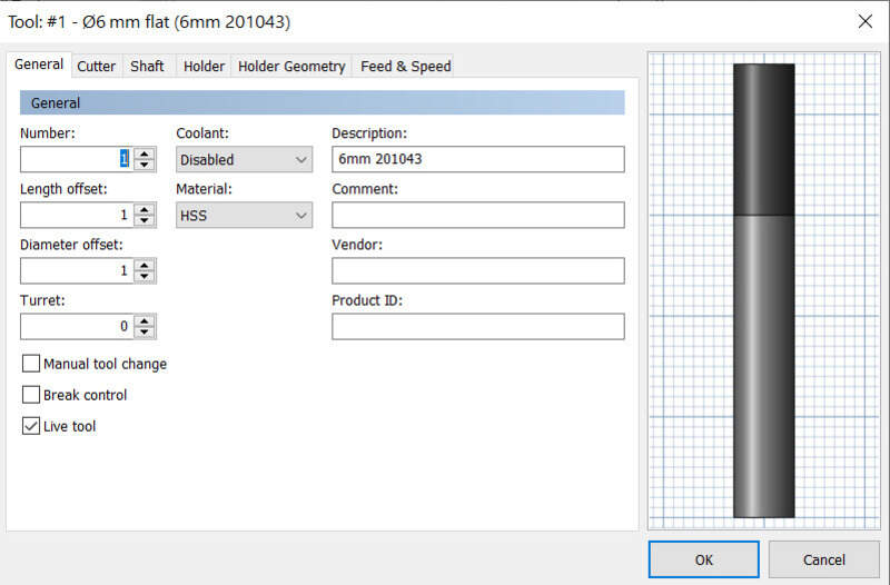
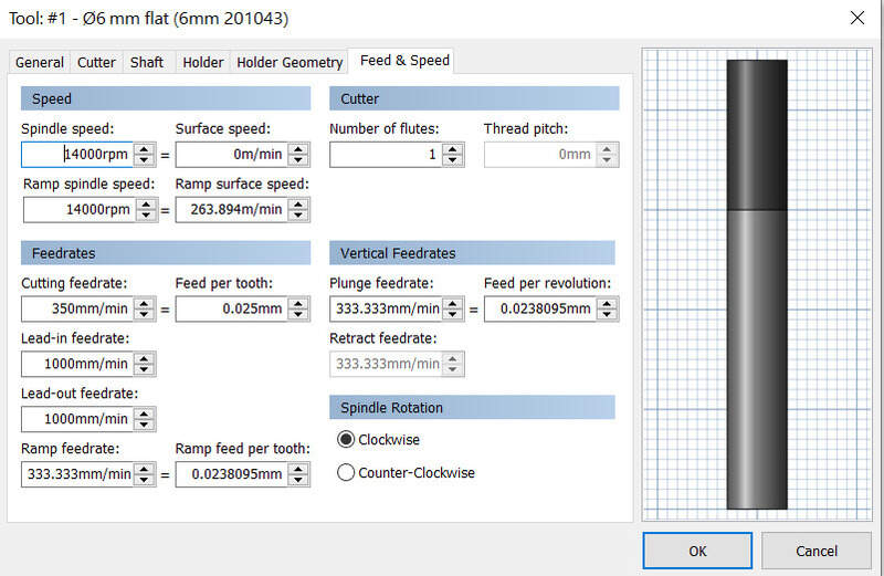
I will be using 14000rpm as it is a bit faster than what is in the datasheet for aluminum.
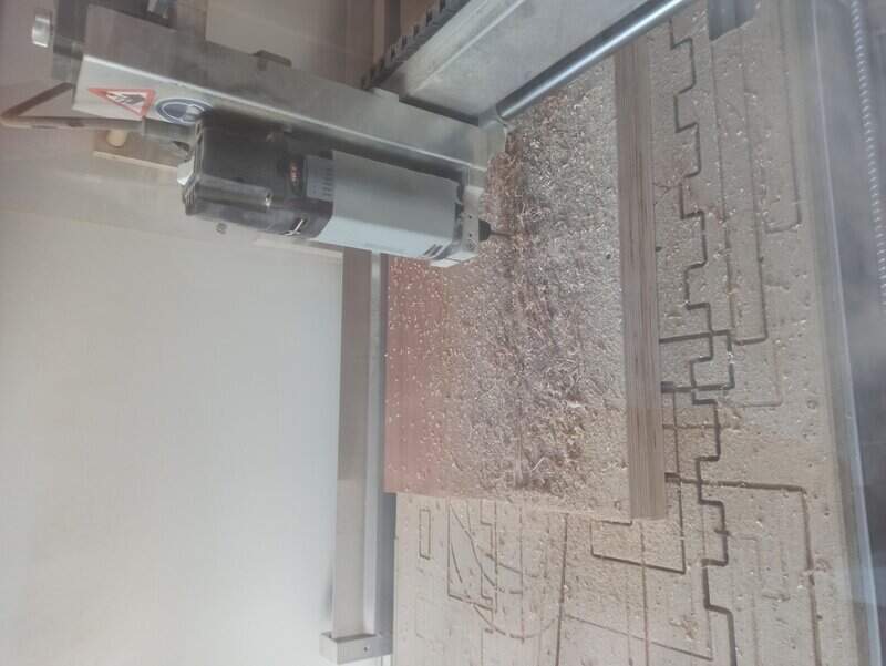
Top face: surfacing
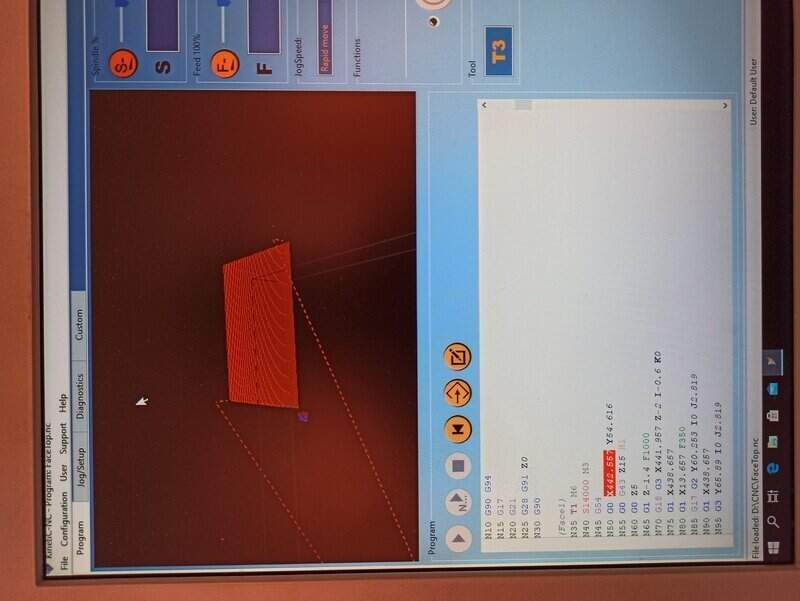
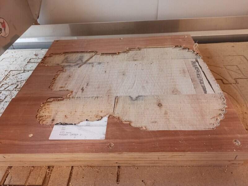
Just like I did with the “test” part, I made a new job, added the stock and axis and created a surfacing process. In the job setup I specified that my guitar should be 2mm below the top of my stock so I will need to surface 2mm.
I processed the GCode and had a look in the Kinetic software to make sure it was all okay.
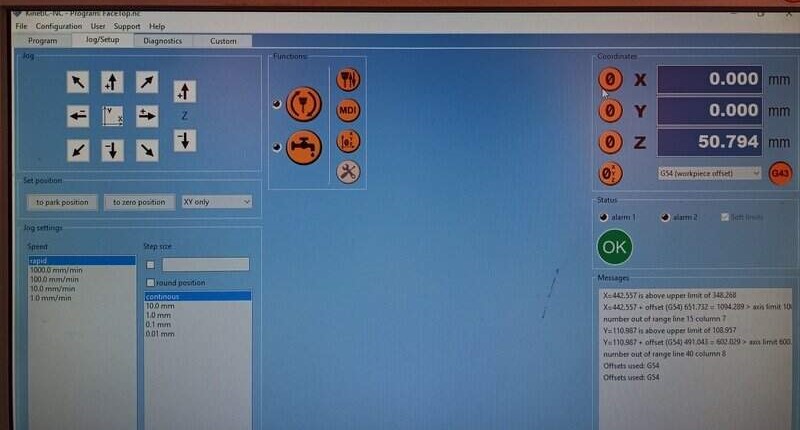
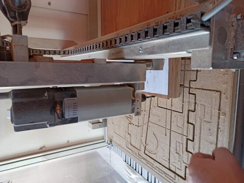
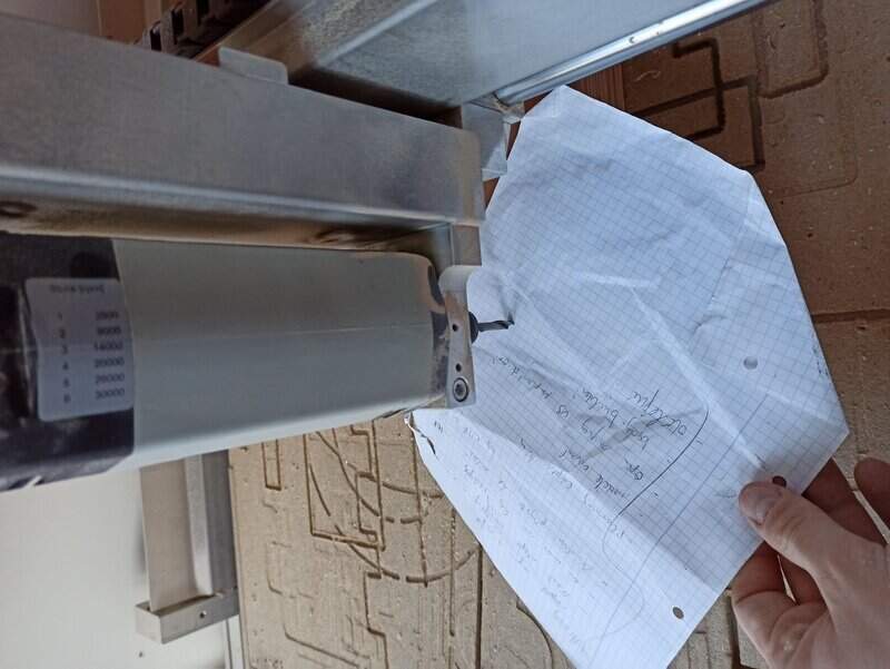
I placed my machine at the top left corner of my stock, as defined as the zero in my job setup, and clicked on zero. Then I had to place a piece of paper and lower the mill until it slightly touches it and I adjusted (0.1 and 0.01mm) until it scratches when the paper, before zeroing my machine.
Then I loaded the CAM and made sure it was all okay.
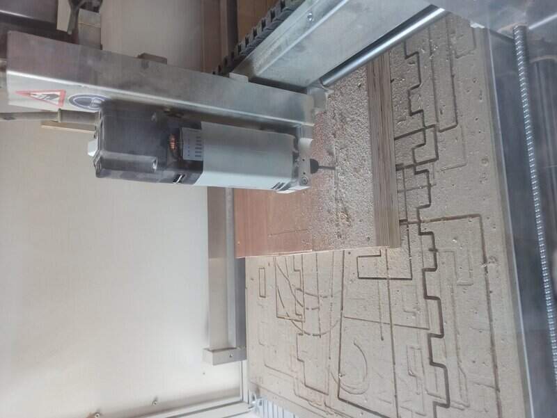
Since it was the first milling I did, I took time to make an “air milling” and make sure the mill did not go outside the stock boundaries.
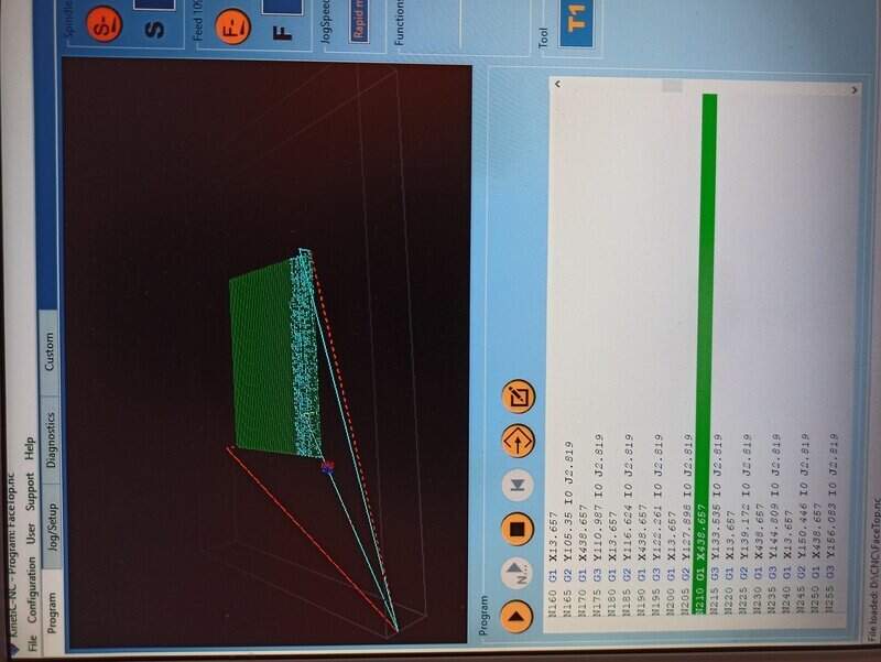
I can now start the program at the correct height.
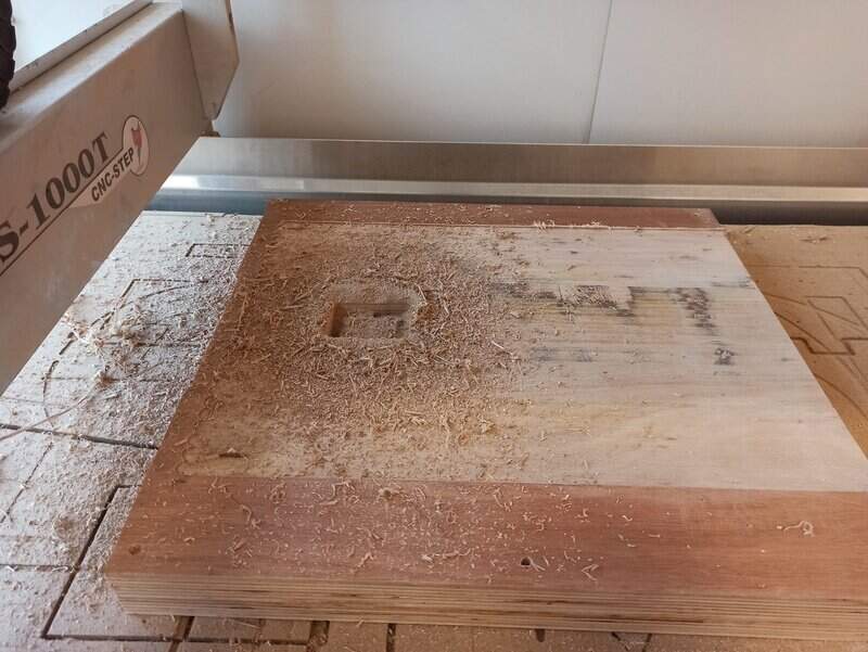
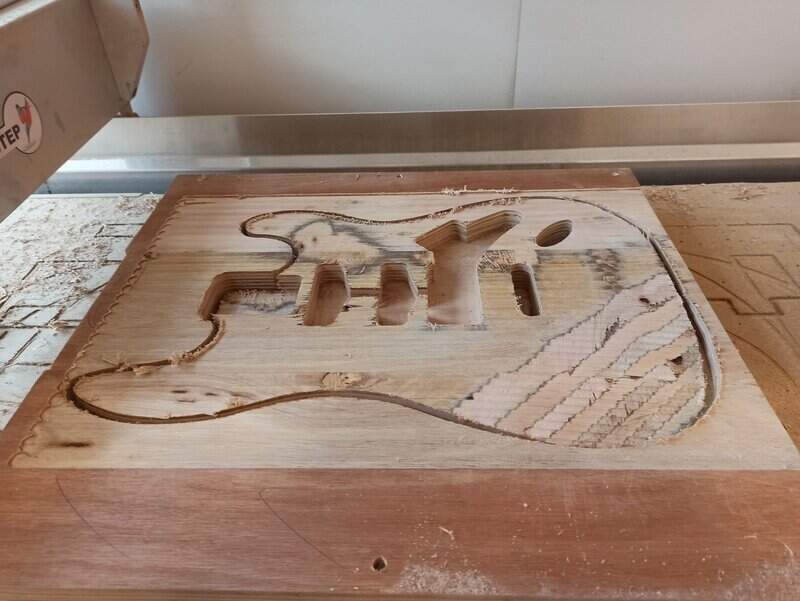
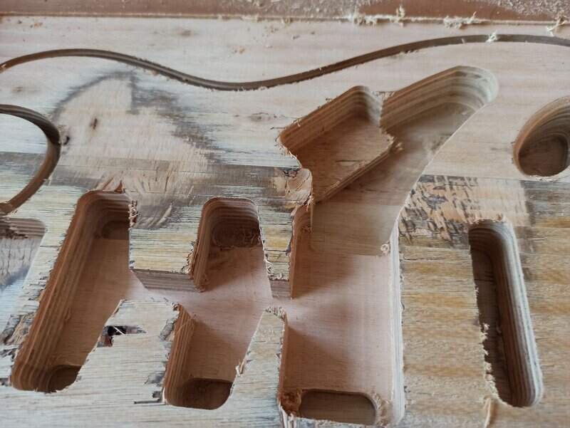
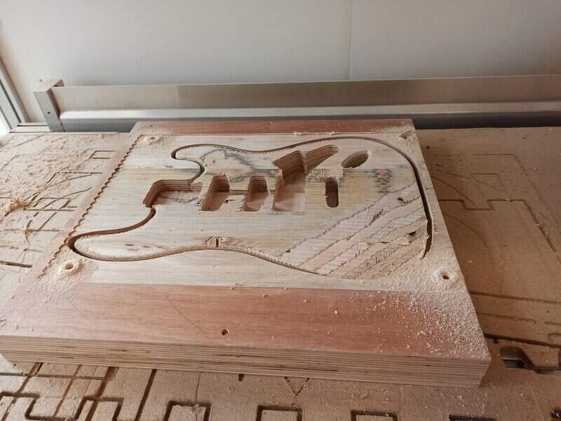
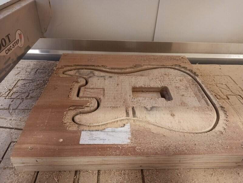
Top face: 2D pocket
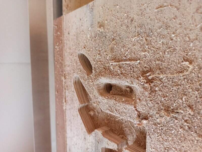
I started with the neck hole/pocket since it is the easier. I did just like for the “test” part above and the result:
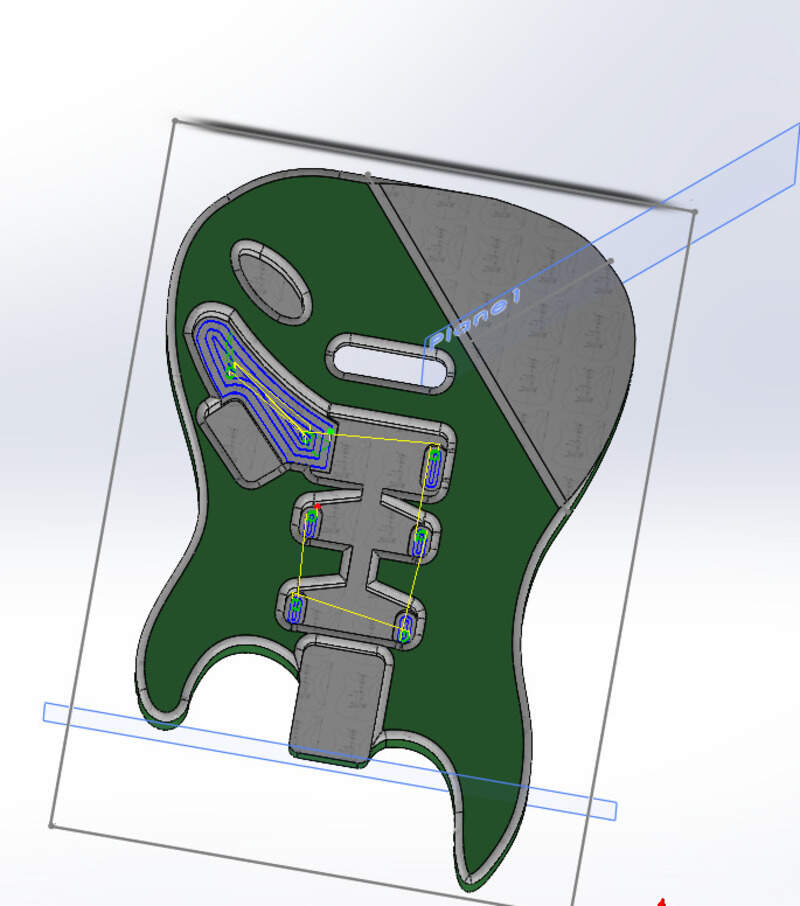
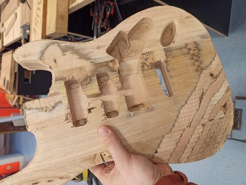
For the central holes, most of them are not of the same depth, however, to avoid making each one at a time, I selected the whole contour and selected the highest face as the bottom height so that everything will be leveled at the highest height.
An extreme attention must be made to the clearance height to make sure the mill won’t jog into the whole wood.
For the bridge part, it goes through the whole part but we’ll make a first half in the face A and the other half on face B. Note that since we have surfaced already, the top height is the stock minus 2mm since I surfaced 2mm.
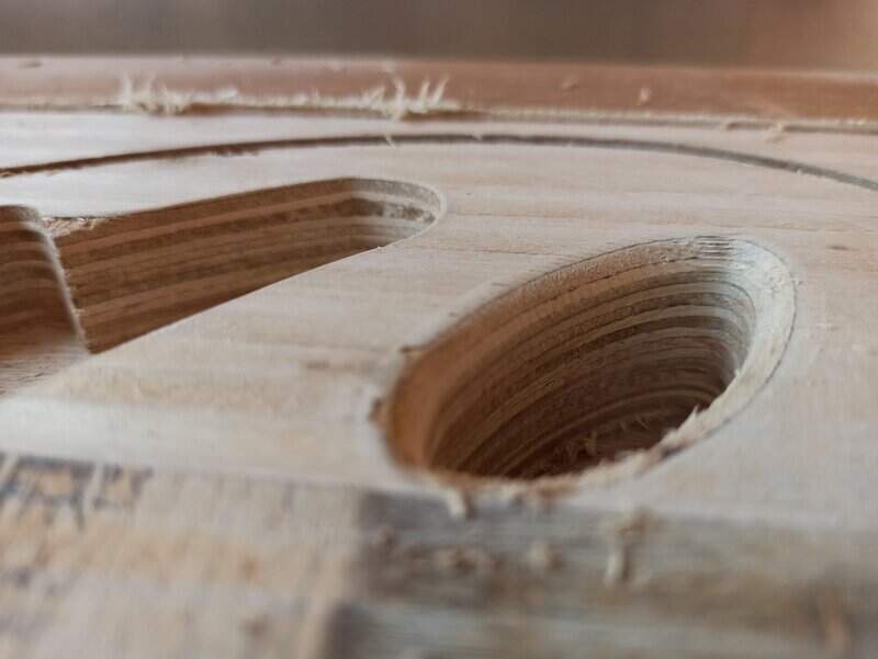
I then did the Jack input hole:
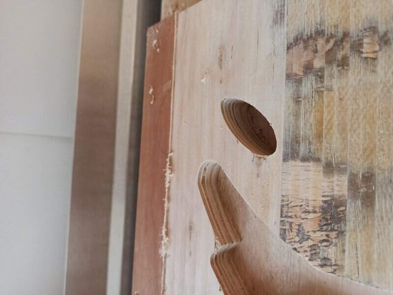
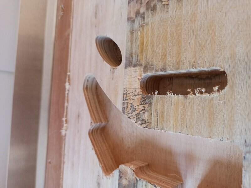
And finished by making the different depth holes:
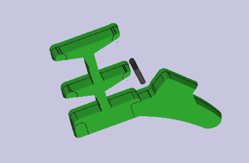
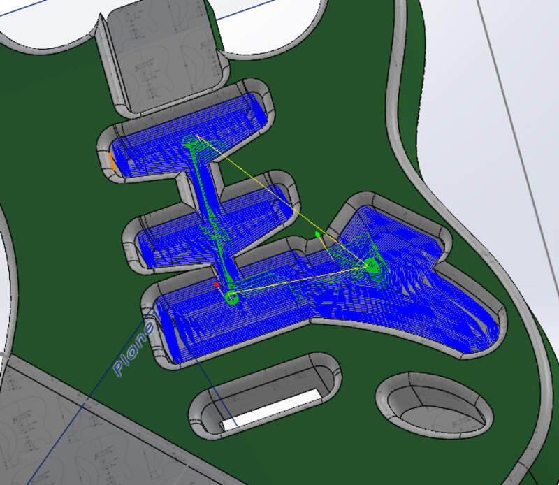
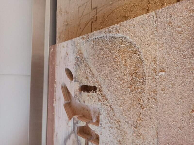
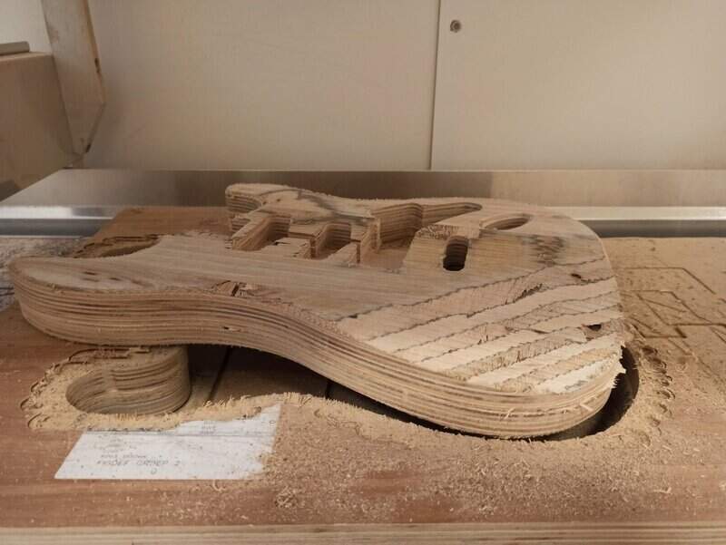
Top face: slope (3D pocket and parallel)
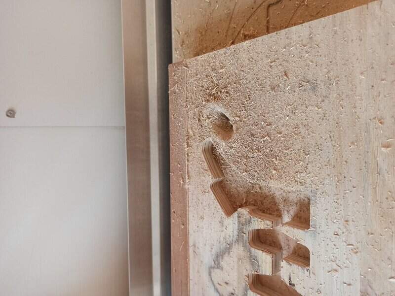
The slope on the top face was a bit harder to setup. Since the height is not constant, I used a 3D pocket clearing to get a rough surfacing and leave only a maximum difference of 1mm (some cusps exist):
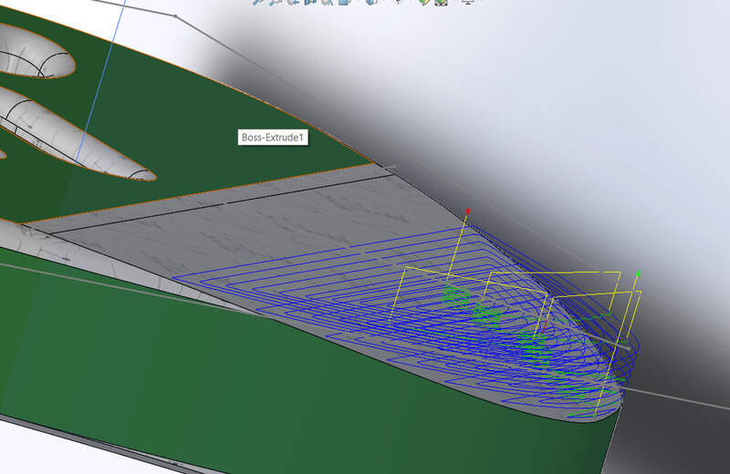
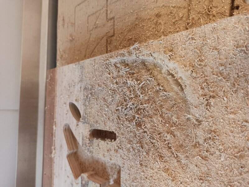
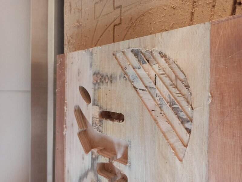
The cusps are very visible but this is normal, this step is to reduce the maximum depth to mill in the next step.
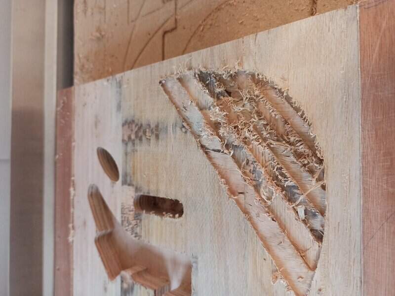
I can now use the parallel process to really follow the slope (there is no stepdown settings here !!! so we need to be extra careful) with the tool and since I used the 3D clearing just before, I know I will have between 0 and 1mm of height of wood, so I can go faster!
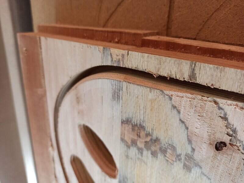
Top face: outline
I used the 2D contour process to do the outline. I have 44mm to cut so I’ll do 20 on this face. However, since wood waste will be stuck in the slot, I’ll only make 10mm in one job then clean thoroughly before doing a second job 10mm below.
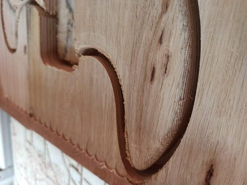
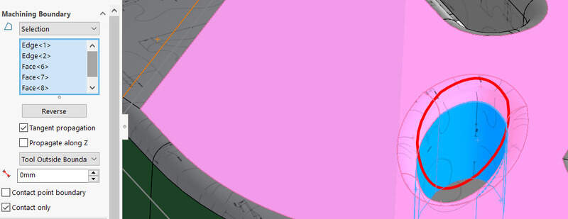
Top face: Rounded edges
For rounded edges on the Jack input and on the outline, I used the parallel process but using the additional check surfaces option and make sure the touch settings was on. That allowed me to force the tool to follow the curve all along.
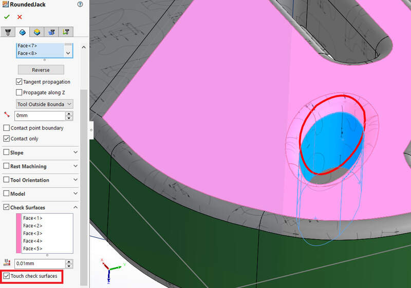
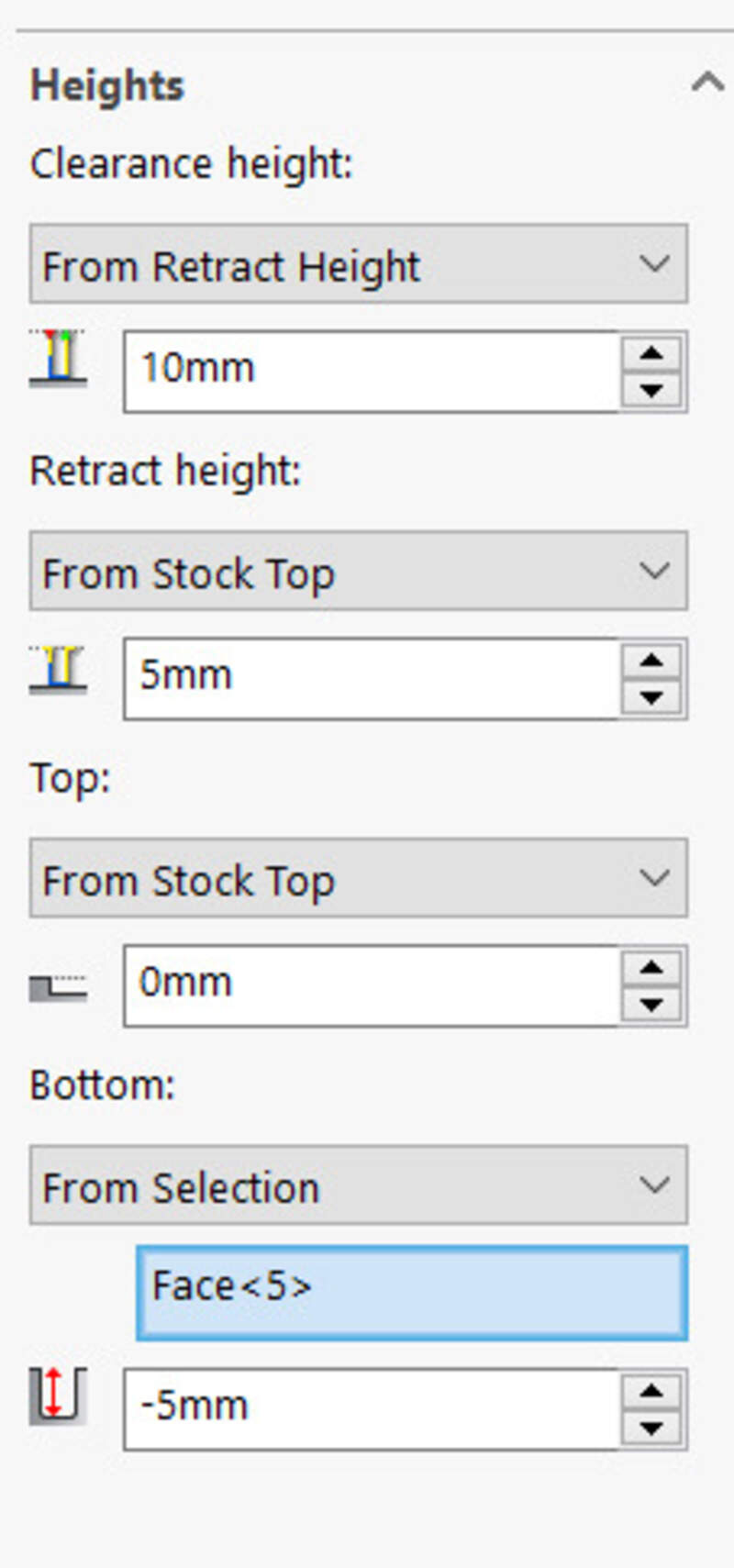
The height is set as : from the surface to the surface -5mm.
I did the same for the outline:
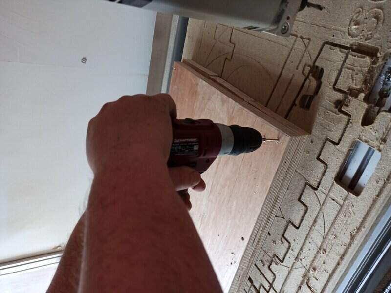
Changing side: Drilling holes
That was the moment I was the most afraid of !. I need to flip my stock around, without losing references and coordinates to be able to mill the other side and complete my guitar.
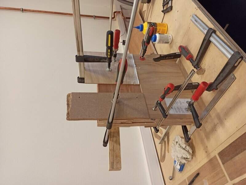
I thought for a long time until I came up with this idea:
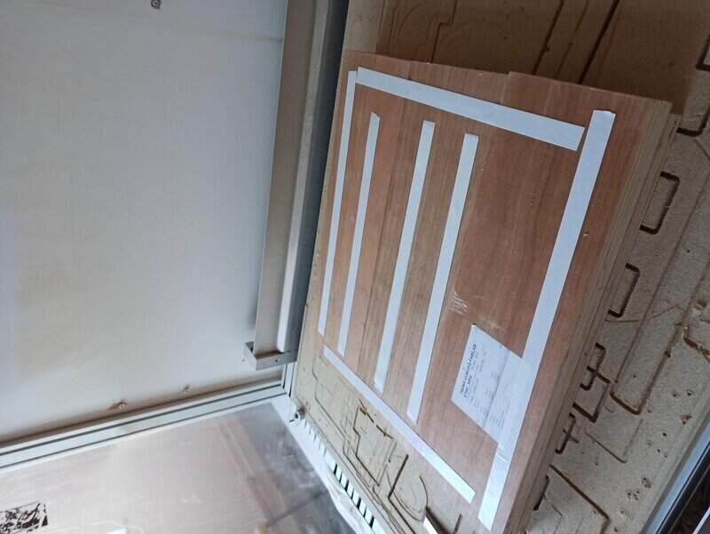
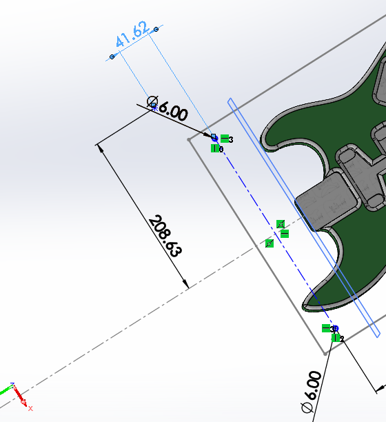
First, I make a new sketch composed of 4 6mm holes which are placed at the 4 corners of my guitar but at the same distance from the rotation axis.
Then, I use the “Drill” operation in the CAM to drill these 4 holes on my stock. I make sure to go at least 30mm inside the stock.
I remove the stock from the CNC and I drill the same 4 holes but at Z = 0 up to Z = -10mm (a bit less than the spoilerboard height).
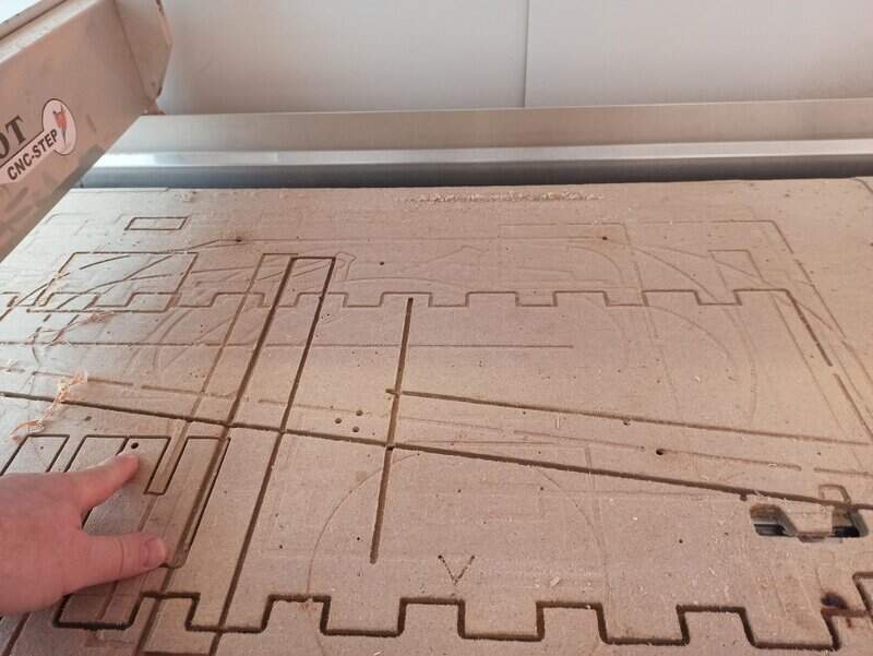
I insert 4 metal bits, recycled from an IKEA furniture in the holes in the stock.
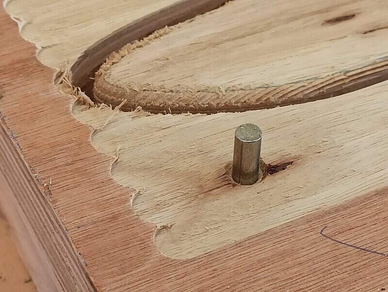
I can now flip the stock and it will perfectly fit the holes on the spoilerboard.
By taking a look at the Gcode, I can know the position of those 4 holes relative to the zero position of the machine. I can therefore also know the position of the flip axis relative to the machine (G54 coordinates).
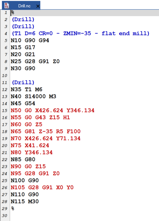
The mean coordinate, i.e. the y coordinate of the flip axis is therefore (346.134 + 71.134)/2 = 208.634, still relative to the zero position of the machine. I therefore know that, after flipping, my machine is now zeroed at -208.634, and still at the same X (41.624). I add a new point in my sketch in a plane that is at 48mm from the top of the guitar (i.e. the distance of the bottom part of the stock) that I will use to set the coordinate of the machine in a new job that will be the bottom face job.
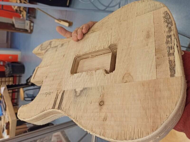
Bottom face
So for the bottom face, it’s all the same, but easier since there is less to do.
What was very important was to first do all the holes and so on, before the outline. The guitar was basically “floating” in the air so if I cut the outline it wouldn’t be held by the stock anymore. Moreover, when doing the outline, I needed to remove the last 19mm. I first did a pass of 10mm. Then a second of 7mm so as to leave a final 2mm holding the guitar body to the stock.
Finally, I hit the last part of the outline with a small chisel at an edge and everything just “snapped” and the guitar was free !
The end result
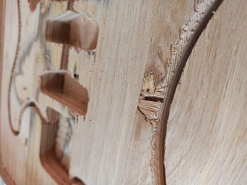
The finish is not perfect and I will probably hand-sand it a bit in the future before applying a vernish but it is still very impressive.
Some stats
The machine jobs lasted for about 14 hours. Moreover, doing the vacuum cleaning, placing things on the board, flipping the board, preparing the CAM and so on, it took me an additional 2 hours. Add to this the work done to prepare the stock: about 2 hours and the CAD design: 4 hours. I was afraid I could not finish in time but the end result is there !
Bonus
I wanted to make a pick protector as well using the laser cutter. But I was so tired of all the machining I actually made it the wrong scale . I’ll finish it later.
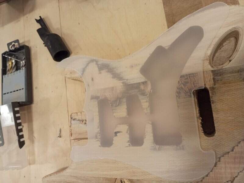
I also would like to engrave a part of the guitar using the laser cutter.
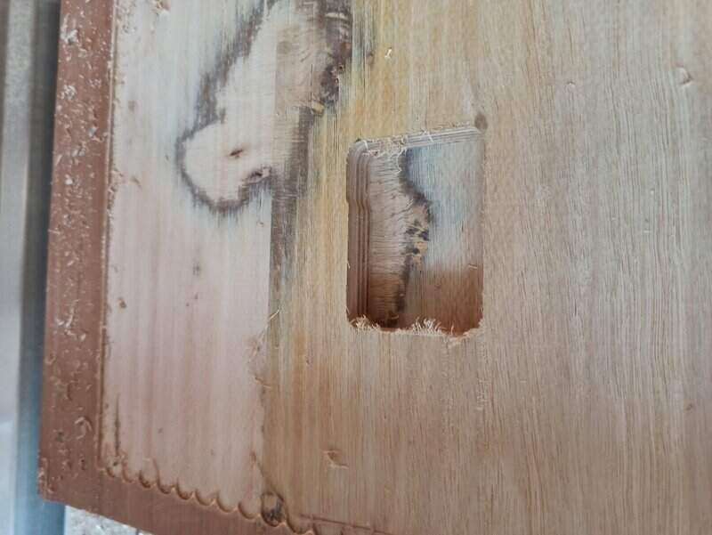
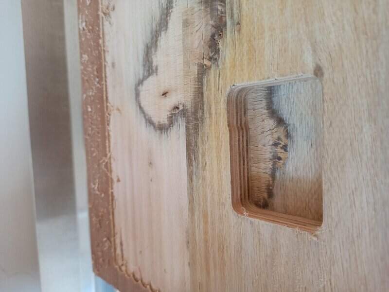
Errors that I did
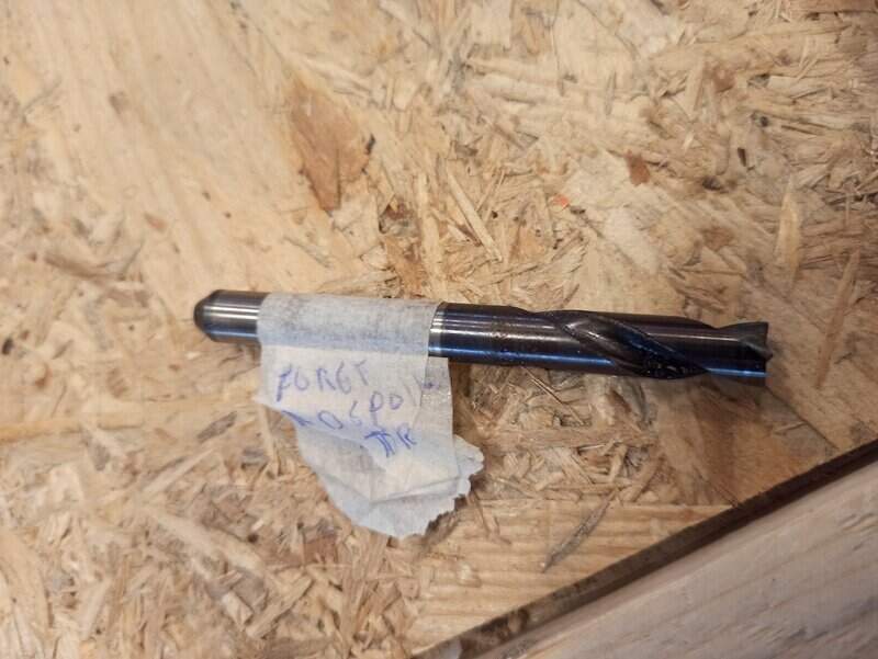
- There is one main error that I did. I found looking around a mill that looked exactly like an 8mm mill. I set it up in the machine, hoping to speed up the surfacing process. Quite fast, it starts smoking a lot in the room. I thought I misentered some parameters and the mill was rotating too fast or slow… Tweaking the parameters yield nothing but more smoke. I removed it and I noticed a little pointy edge at its end. Looking online I found that bits like these one are actually made to unsolder metal sheets, despite looking almost exactly 8mm mill. So it was normal that it smokes as it wasn’t made for it to be used in a CNC ! I’ll check better next time ! Luckily, my stock was not hurt too much neither was the machine.
- A little mistake is that instead of surfacing the whole top part (though constrained to a square) I could just, like I did for the bottom part, surface the contour of the guitar with a small offset. I could have gained 30min to 1h just doing that!
My design files
All the CAD design, CAM processes and Gcode are available here: My Design files